 alberto nunez
-
1Bill Of Materials
-
2Printed Circuit Boards
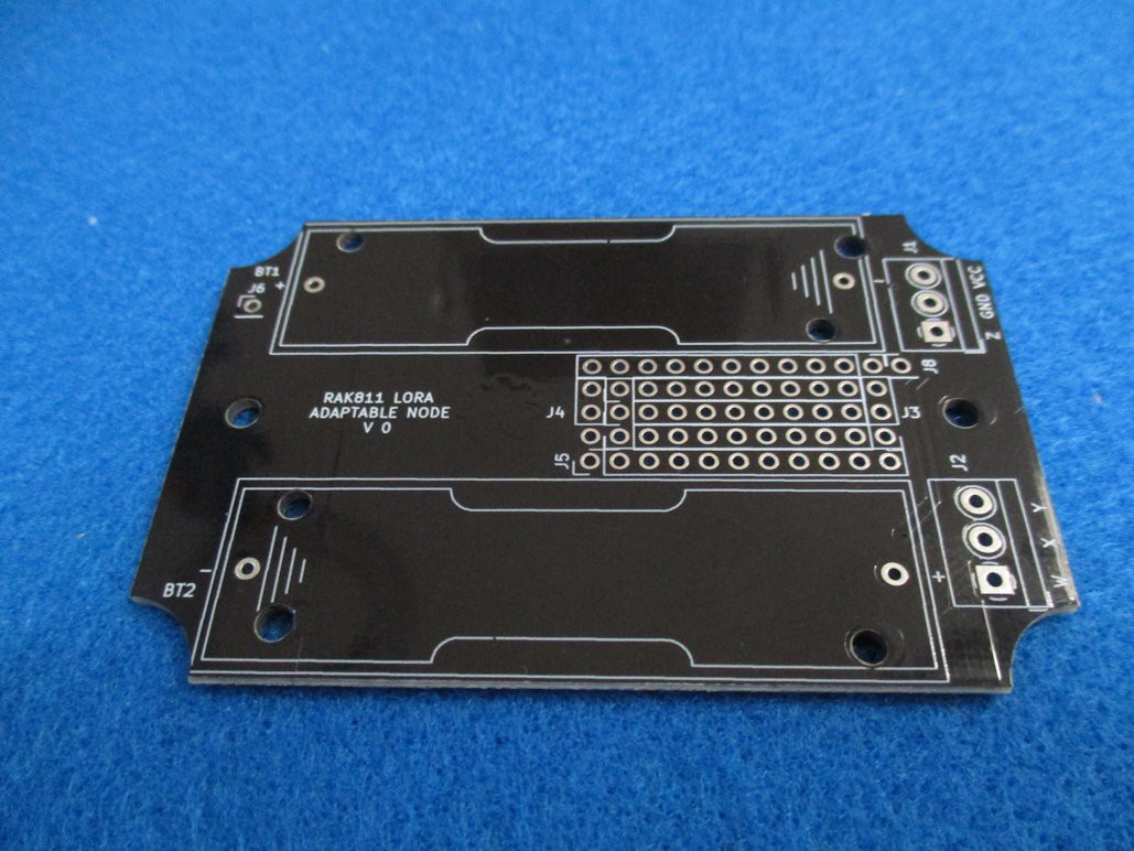
- Main circuit board RAK811 LORA ADAPTABLE NODE
- Breakout RAK LORA ADAPTABLE NODE BREAKOUT 2AA
-
3Software
- Firmware RAK811 RUI SWITCH SENSOR
-
4Customization
The project is divided in four main aspects: power source, enclosure, antenna and expansion which can be modified for the exact requirements. Finally a sample application is given as a way to show how to implement your own sensor solution.
Power source
The device can work from 1.8v up to 3.7v. There are many alternatives to power it:
- 2 x AA alkaline batteries. JP1 jumper positions 1-2 shorted.
- 1 x 14500 lithium battery. JP1 jumper positions 2-3 shorted. The BT2 battery holder could be removed, freeing up some PCB space.
- External power applied to J1 screw terminal. BT1 and BT2 battery holders could be removed, freeing up even more PCB space.
Enclosure
The PCB fits inside a “generic” unbranded 83x58x33mm waterproof plastic enclosure. These enclosures came in multiple flavors: gray, white, black, clear lid, wall mounting tabs. The board is fixed to the enclosure by two self tapping screws.
-
5Expansion
![]()
![]()
The prototyping area contains through hole soldering pads routed to all pins of RAK811 module, plus some small amount of free connected pads for prototyping. Connections for outside detachable sensors are provided via W,X,Y,Z screw terminals. If the vast prototyping area isn’t enough, female pin headers could be soldered and an expansion board could be plugged in.
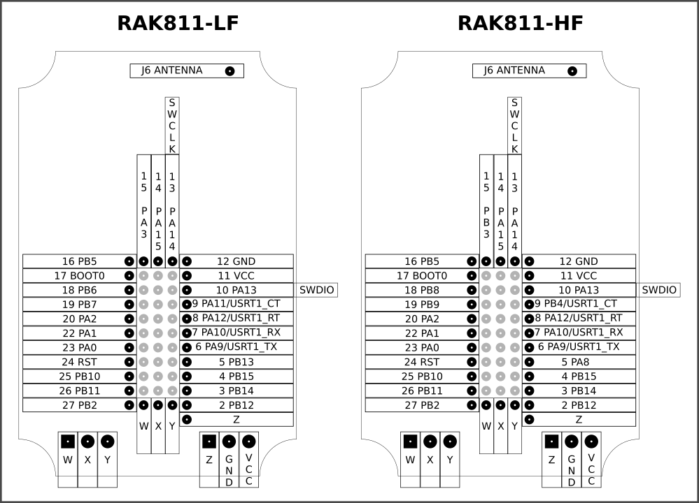
Notice that RAK811-LF and RAK811-HF have slighter differences in some i/o pinsAntenna options
Internal spring antena soldered on J6, JP2 jumper positions 1-2 shorted. External antenna using U.FL. connector, JP2 jumper positions 2-3 shorted.
Provisioning
As the code was derived from a RAK Wireless existing product, it uses de same AT commands for provisioning using UART. Here is the manual with the complete AT commands.
-
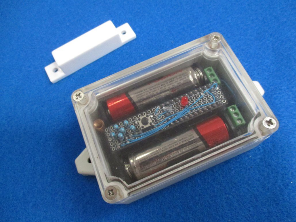
6Sample application
![]()
![]()
![]()
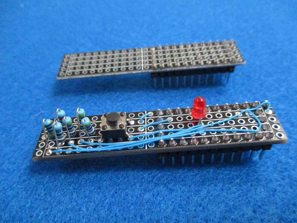
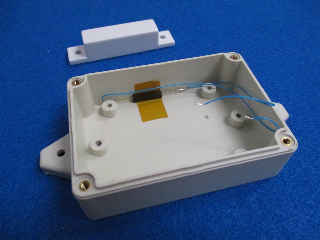
The sample applications consist in a LoRa magnetic switch sensor which transmits a packet when the switch opens or closes. A very small reed switch is installed in one of the walls inside enclosure. Breakout board was used to install the supplementary electronic components: Led indicator, pullup resistors, test button, and voltage divider for battery monitoring.
Any other kind of switch sensor (ball inclination sensor, spring vibration sensor, etc.) could be added!
PVDF wire was used to make connections because the insulation resists pretty well soldering iron abuse!. For more information about the PCB or the firmware, don’t forget to read the linked repositories.
RAK811 based LoRa Node powered by AA batteries
LoRa node conceived for experimentation. Easy to interface to multiple kind of sensors.
Discussions
Become a Hackaday.io Member
Create an account to leave a comment. Already have an account? Log In.