Close
0%
0%

The Slowest Video Player with 7-Colors!

Watch your favorite films at 1 frame per minute

Similar projects worth following
This is a digital picture frame that plays a movie frame by frame at a rate of one frame per minute.
Images appear on a 7-Color E-Paper display.
The whole movie is stored as a sequence of jpeg images on an SD-Card.
An STM32 microcontroller reads the files from the SD-Card and updates the display.

Code and 3D models are available on GitHub.

Last year I saw this video on Youtube that featured a 7-Color E-Paper display from Waveshare. I immediately thought it was cool and after seen the Slowmovie project by Mike Szczys I had to make my own.

As far as I know, nobody has made something like this with a color E-Paper display so even if it isn't a new concept, it brings a new twist to the game.

The plan is to make a standalone battery-powered device in a nice 3D printed case. It has to be as low power as possible since I want the batteries to last at least a couple of months. E-Paper displays are ideal for this task because they draw power only when the image is changing.

Logs:

Display Testing  (Measuring the display power consumption)

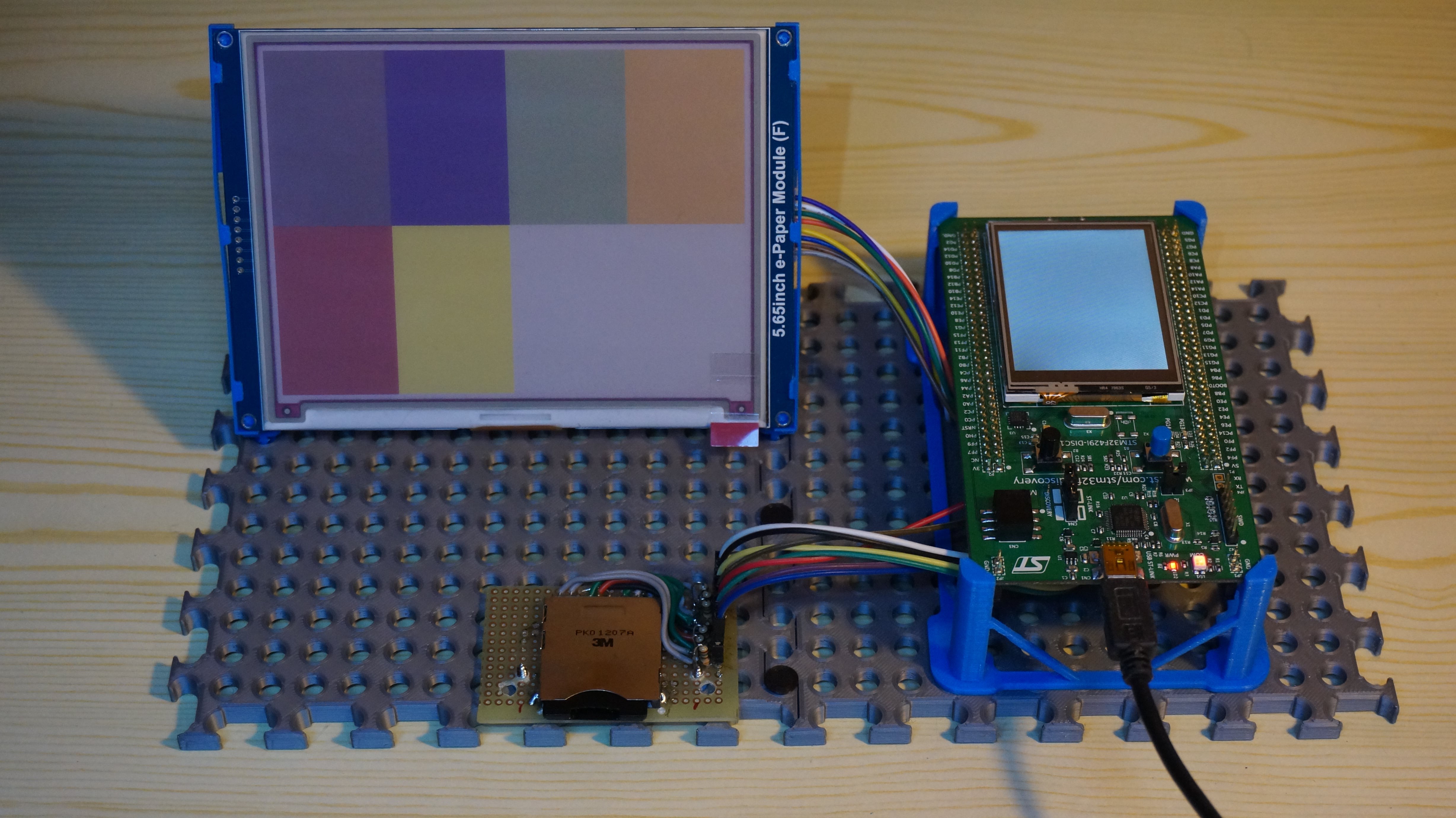
Display Test Fixture (Making a text fixture to hold the display and the STM32 Discovery board)

JPEG Decoding (Decoding jpegs on the STM32)

Schematic and Power Consumption (RevA PCB schematic and battery life estimation)

PCB and 3D Printed Enclosure (3D Printed enclosure prototype)

Folder Structure and Video Conversion (SD folder structure and how to extract jpegs from mp4)

RevA PCB (troubleshooting) (PCB Inspection, first power-up, programming the micro)

Final Assembly + Power Measurement (Putting all the pieces together)

STM32 Standby Mode, FLASH vs Backup SRAM (Storing data into internal FLASH and overcoming write/erase cycles limitation)

3D Printed Test Fixture.rar

RAR Archive - 582.78 kB - 02/13/2021 at 16:25

Download

  • STM32 Standby Mode, FLASH vs Backup SRAM

    Manuel Tosone08/07/2021 at 07:22 0 comments

    FLASH vs Backup SRAM

    STM32 microcontrollers have different power modes, each of which is a compromise between power consumption and wakeup time. Standby mode features the lowest power consumption. In this mode, the CPU and peripherals are stopped, clocks are switched off, SRAM and register content are lost. The only peripherals that keep running are the RTC with its 32.768KHz oscillator and the backup SRAM. The microcontroller exits standby mode after a physical reset or an interrupt from the RTC clock. In either case, the CPU has lost all of its state, all the variables are gone and code execution restarts from the beginning.

    There are two areas of memory that don't lose data during standby mode: FLASH and backup SRAM. Backup SRAM is the simplest to use, it consists of 4 Kbytes of memory that remains powered during standby. You just write to it like normal RAM. The only problem it has is that if power is lost (while changing the batteries for example) the contents are lost.

    FLASH memory is not so easy to use, it is slower and has limited write/erase cycles but it maintains its content without needing power. The limited number of cycles is a big deal for this project. Every 24 minutes a string containing the path to the currently displayed frame has to be stored. This means 60 writes per day, with only 10000 write/erase cycles available the FLASH will only last 166 days.

    Overcoming the Write/Erase Cycles Limitation

    The FLASH memory of the STM32F405 is divided into 12 sectors, 0 to 11. Although it is possible to write to any sector, care must be taken to not overwrite the firmware. The compiler puts the code in memory starting from the first sector so the last one should be safe to use. To erase one byte inside a sector, the whole sector must be erased. Erasing a sector writes 0xFF to every byte in the sector, programming a byte inside a sector writes zeros to the appropriate bits. Sector 11 is 128KB in size, instead of erasing it each time, it can be erased once, data can be written sequentially until it is full and then erased again. This fixes the original write/erase problem and creates a new one. If every write is to a different location, how do you know from where to read?

    Implementation

    To keep things simple I made a struct that is 32 bytes long. The first 22 bytes store the actual data, the magic number is used to optimize the search algorithms and is always written to 0x5A, the checksum is to detect data corruption in case power is lost during a write.

    Writes are always aligned to 32 bytes. A 128KB sector can store 4096 of these structs. 

    typedef struct
    {
        char file_path[22];    //File path string
        uint8_t padding[8];    //Padding to make the struct 32 bytes
        uint8_t magic;         //Magic number (0x5A = entry contains data)
        uint8_t checksum;      //Checksum for the entry
    } FlashEntry_t;

    To write a new block of data, start from the beginning of the sector and search for the first block of 32 bytes that are not already in use. If there is no space erase the sector end start from the beginning. To optimize the search, the magic number is checked first, if it is 0xFF the other bytes are checked else the block is considered already in use.

    /*
     * Finds the address of the first empty entry
     * returns null if no valid entry is found
     * */
    static FlashEntry_t* FLASH_FindFirstEmptyEntry(void)
    {
        FlashEntry_t* pt = (FlashEntry_t*)_FLASH_STRT_ADDR;
    
        while(pt <= (FlashEntry_t*)(_FLASH_STOP_ADDR - sizeof(FlashEntry_t)))
        {
            //Check if the entry is empty (check magic first)
            if(pt->magic == 0xff)
            {
                uint8_t t = 0xff;
    
                ...
    Read more »

  • Final Assembly + Power Measurement

    Manuel Tosone07/03/2021 at 13:49 0 comments

    Final Assembly

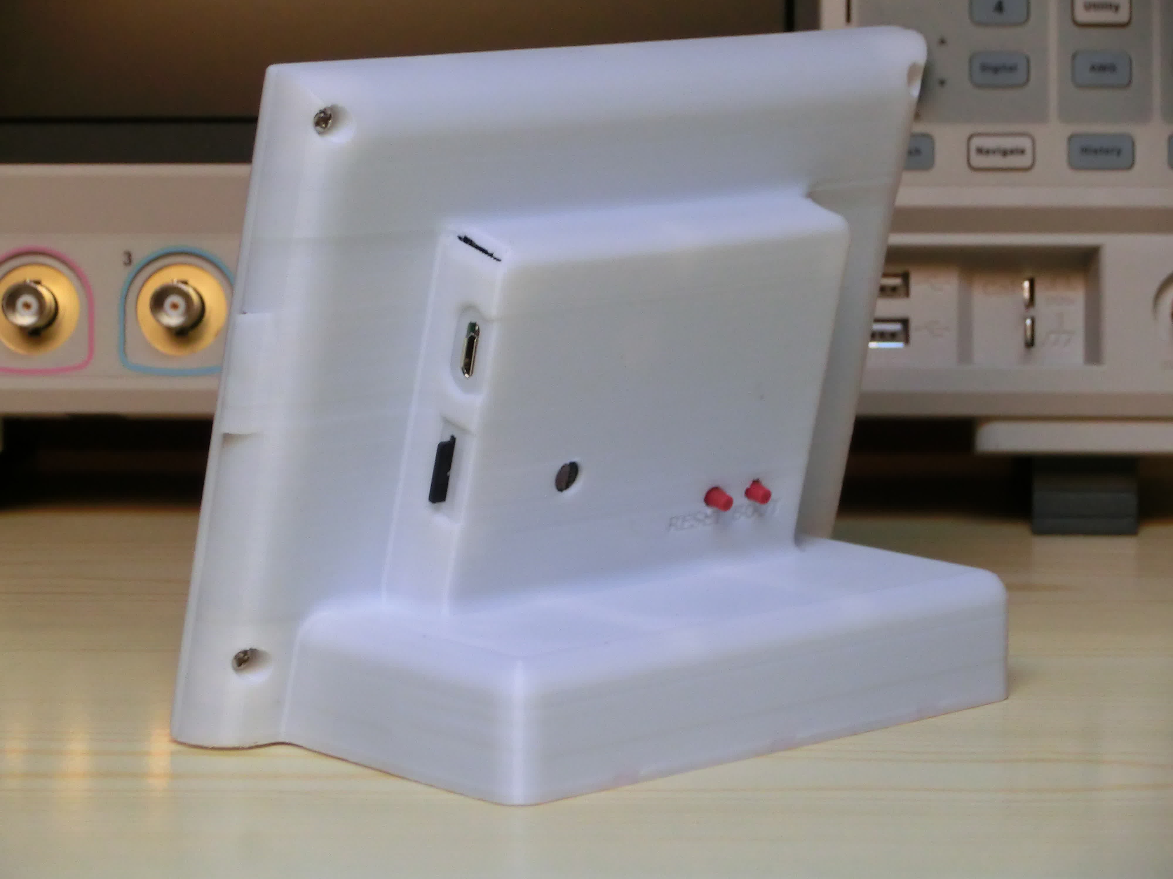
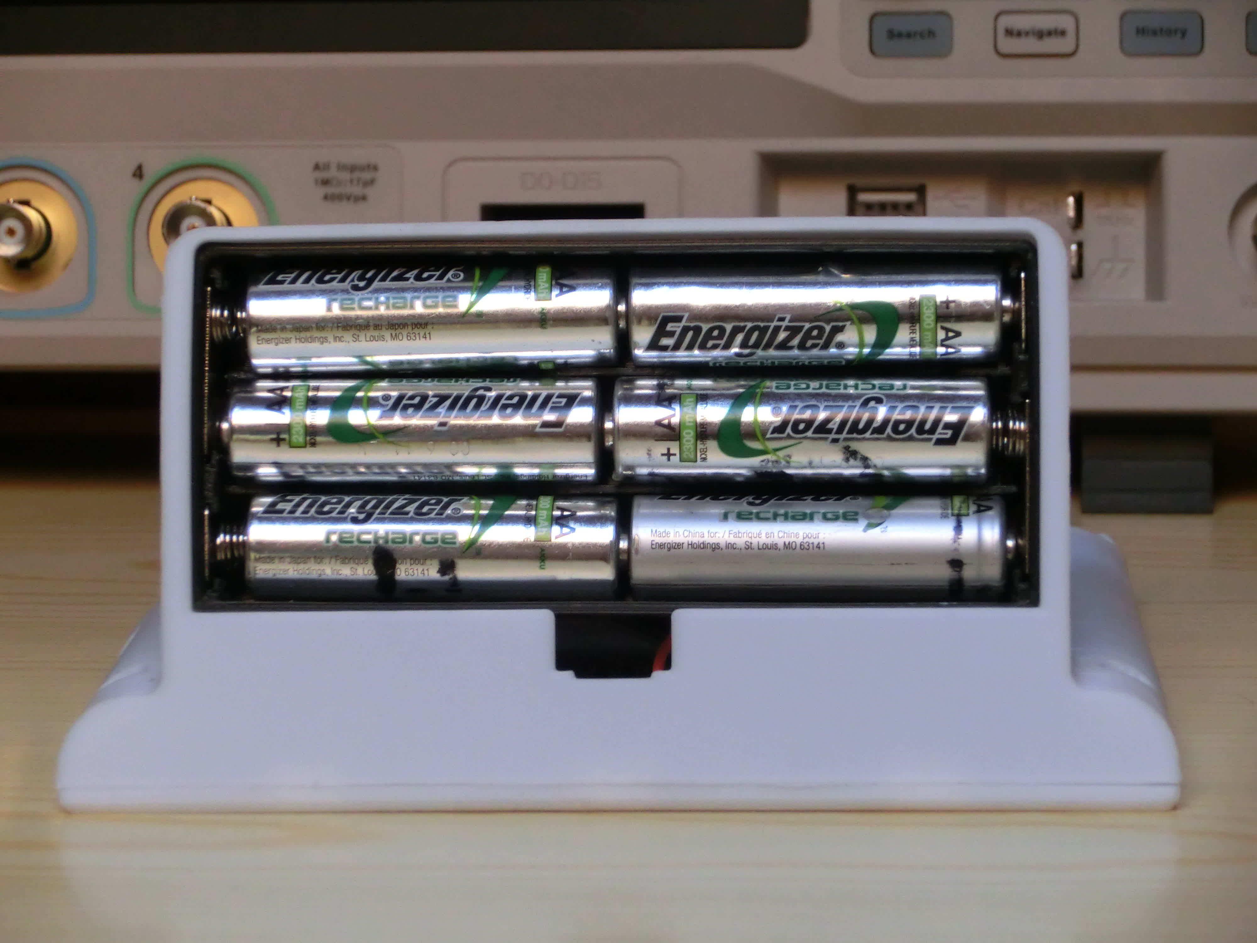
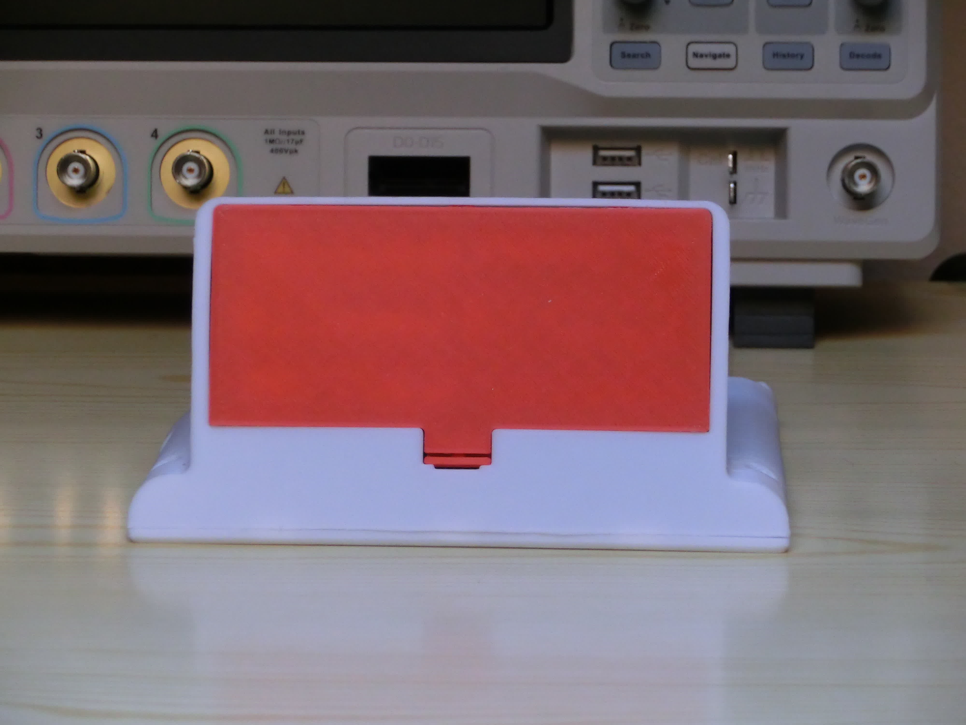
    Finally found the time to work on this project again. All the pieces are assembled in the 3D-printed enclosure.


    Power Consumption

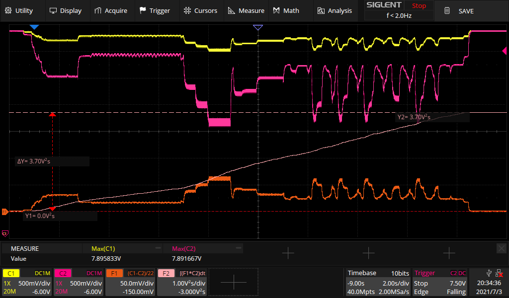
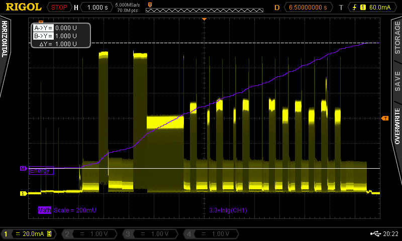
    To measure the power consumption I've used a 22 Ohm shunt resistor in series with the batteries. The yellow and pink traces represent the voltages before and after the resistor. The orange trace is the current, computed using the math function of the scope. The last trace is the energy, computed by integrating the product of C2 and F1 over time.

    The energy required for one update is 3.7J, since the display updates every 24 minutes, the device has an average power consumption of 

    Knowing this it is possible to estimate the battery life. With 6 AA batteries, each with an average capacity of 3Wh, the total capacity is 18000 mWh.

  • RevA PCB (troubleshooting)

    Manuel Tosone04/04/2021 at 19:06 2 comments

    Hi everybody, PCBs finally arrived.
    I ordered them from JLCPCB, this was the first time that I had PCBs assembled.

    Visual inspection and I have nothing to say, quality is pretty good, a quick check with the multimeter to make sure there are no shorts on the power rails and I'm ready to solder the connectors.

    Time to program the microcontroller, as a programmer I'm using the same STM32 Discovery board that I was using for testing. By removing the two jumpers on CN4, the integrated ST-LINK programmer is disconnected from the board and the programming signals are exposed on CN2.

    So I applied power with an external power supply, connected to the programmer, and... the micro wasn't detected.

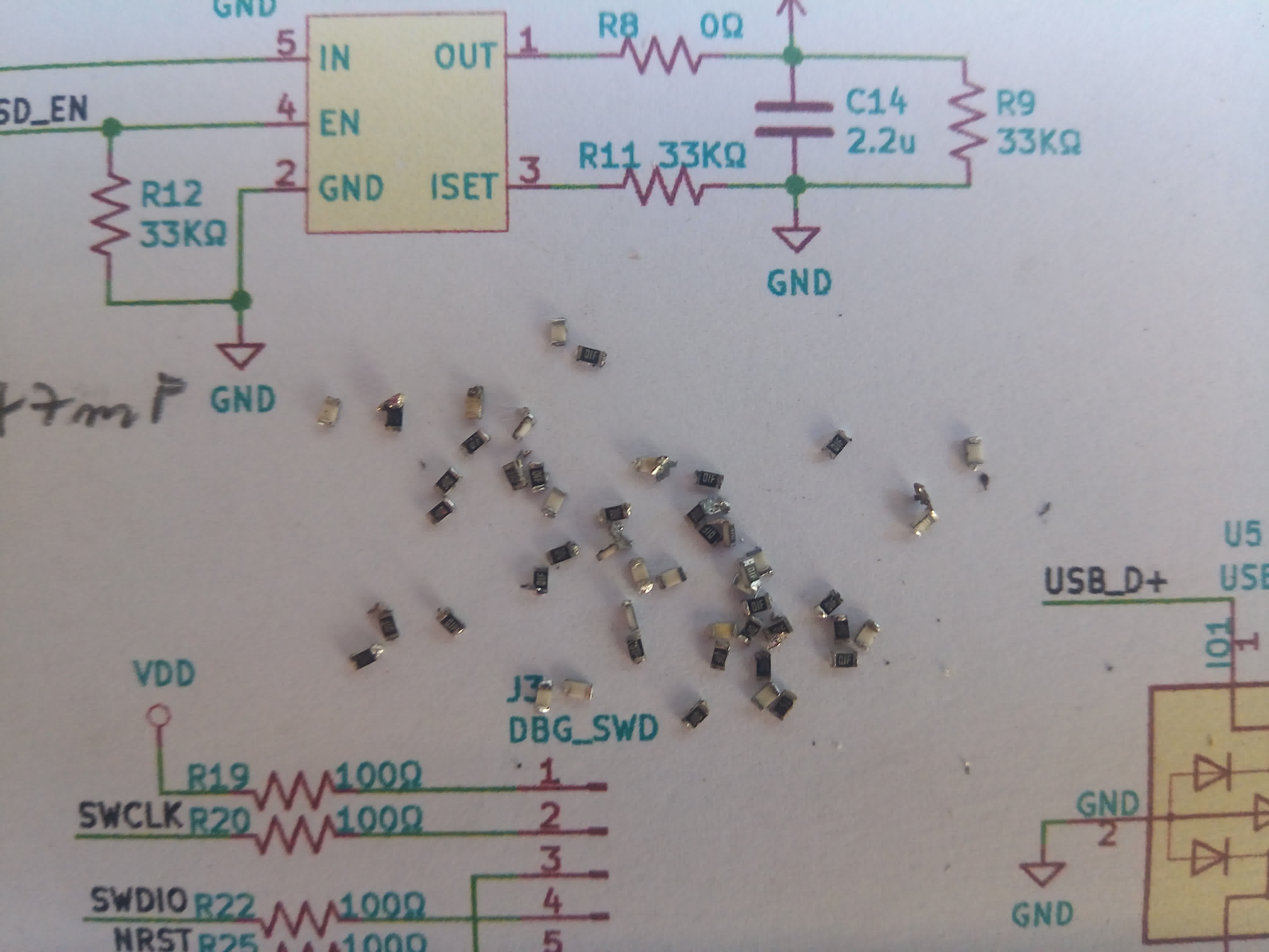
    Ok, troubleshooting time. The first step is to check voltages, I measured the VDD on one of the bypass caps and it was 3V, power is good. Next, I measured the VDD on the programming connector and it was 1.6V. The only thing in series with the connector is a 100 Ohm resistor, maybe I connected something wrong and the programmer is loading it down? Disconnected the programmer and measured again, no change, still 1.6V. Ok, this doesn't make any sense, there's a voltage drop across a resistor without any current. Let me check the resistor value just to make sure, switch the meter into resistance mode, take a measure and... 10 MOhm.

    Ok, so what's happening is that what was supposed to be a 100 Ohm resistor is instead 10 MOhm, now it makes more sense, when I measure the voltage the meter is loading down the circuit. Next question is, how has this happened, I double-checked the BOM before placing the order, this can't be my fault, right? Let me check on the schematic and... no It's my fault, I had specified the wrong part number for all the 100 Ohm resistors.

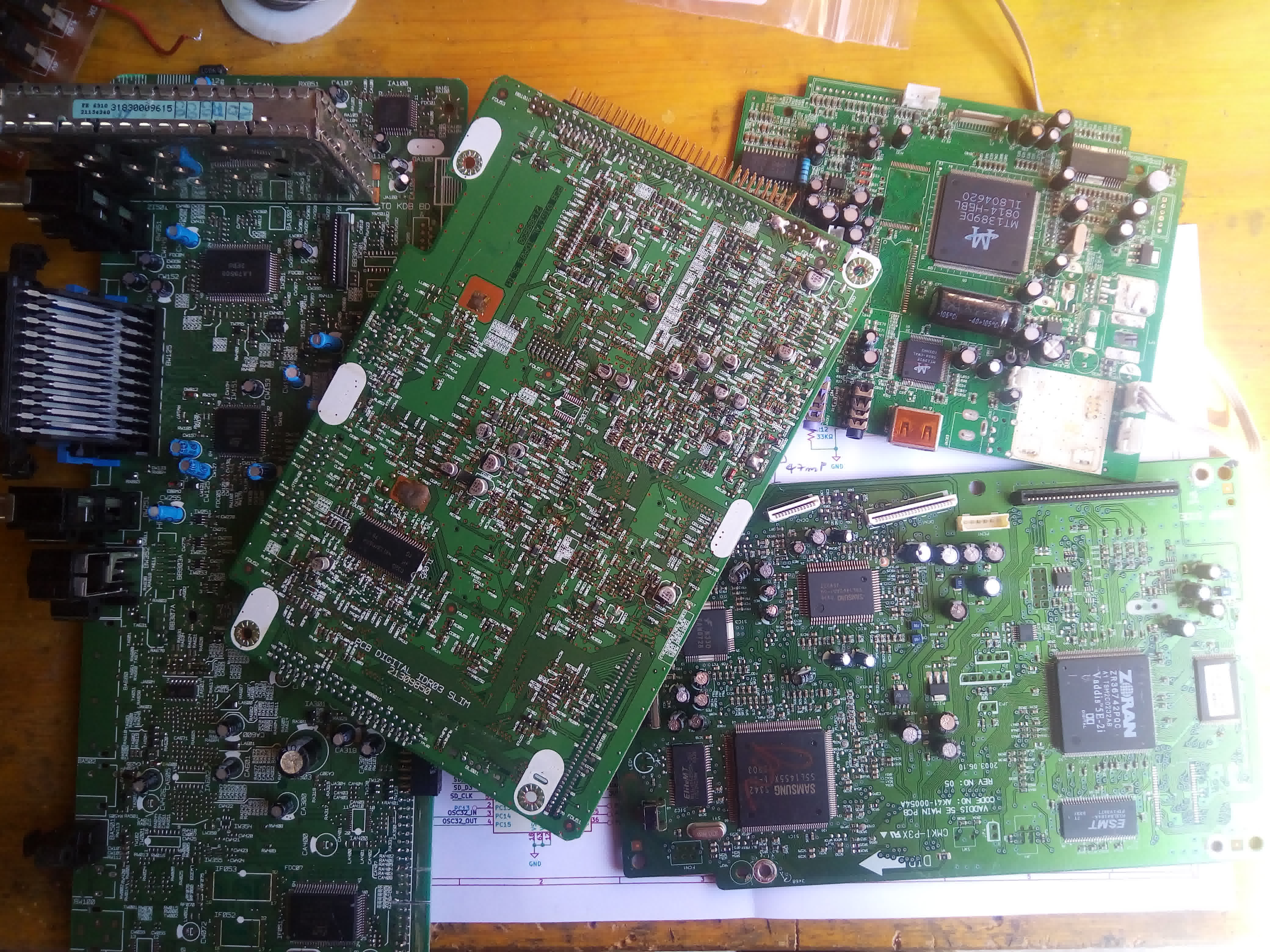
    Now that I know what's wrong, it's time to fix it. The only problem is that I don't have a stock of 100 Ohm 0603 resistors, luckily I have salvaged plenty of boards, time to disorder some resistors.

    Does anybody need 10 MOhm resistors?

    I've replaced all the resistors, let's try again. This time I connected the programmer, the micro was detected correctly and I was able to program it.

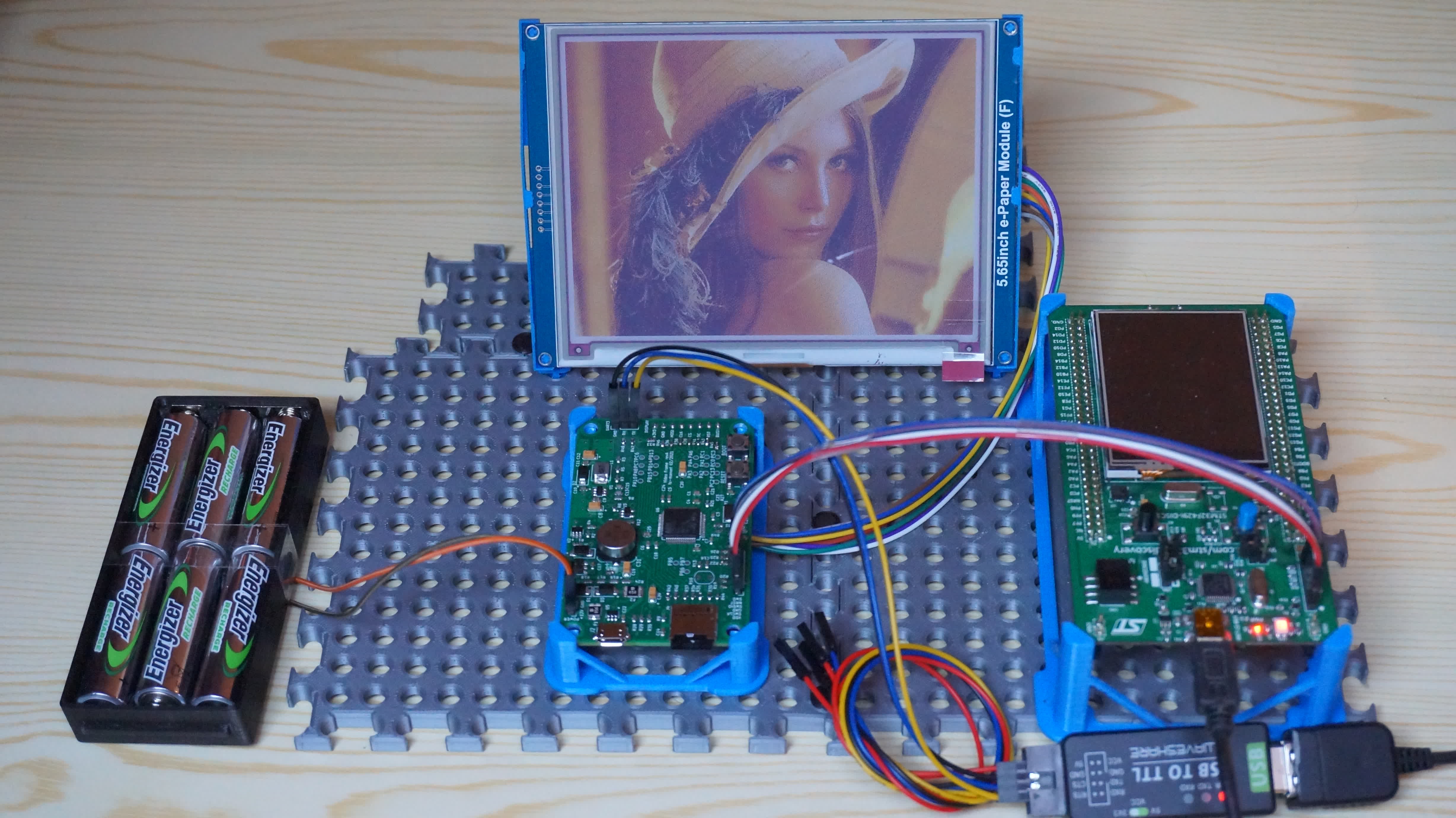
    This is my current setup. In the middle is my new board connected to the display. the STM32 Discovery on the right is used as a programmer, the USB to Serial converter is used to send commands to the micro. Power comes from 6 NiMH AA cells.

  • Folder Structure and Video Conversion

    Manuel Tosone03/18/2021 at 15:30 0 comments

    Folder structure

    Hi, everybody. With this log, I want to address how I go about generating the image files to load into the SD card and its folder structure. One of my goals was to be able to load more than one movie at a time. The solution I come up with is to have a folder for each movie in which the frames are stored.

    /-FOLDER1/
    |        |-0000.jpg
    |        |-0001.jpg
    |        |-0002.jpg
    |        |-...
    |
    |-FOLDER2/
    |        |-0000.jpg
    |        |-0001.jpg
    |        |-0002.jpg
    |        |-...
    |
     -FOLDER3/
             |-0000.jpg
             |-0001.jpg
             |-0002.jpg
             |-...

    Video conversion

    To extract the images from the video file I use a command-line program called ffmpeg. The nice thing about this program is that it has some predefined filter that you can apply in sequence to achieve practically anything you can imagine.

    ffmpeg -hwaccel auto -i input_file.mp4 -vf "fps=1,\
        scale='if(gt(a,600/448),-1,600)':'if(gt(a,600/448),448,-1)',crop=600:448,\
        histeq=strength=0.08:intensity=0.2,\
        eq=saturation=1.5:contrast=1.2:gamma=1.6:gamma_weight=0.8"\
        -pix_fmt yuvj420p -q:v 6 %04d.jpg

    What the command does is best explained by the following diagram. First, the input file is decoded, then the frame rate is dropped to 1 frame per second. The frames are then scaled and cropped to the display resolution. After that, some color correction is applied before finally saving the images as jpegs. Preprocessing the images by raising the contrast and color saturation makes the images on the display appear more natural and compensates for the display low color count.

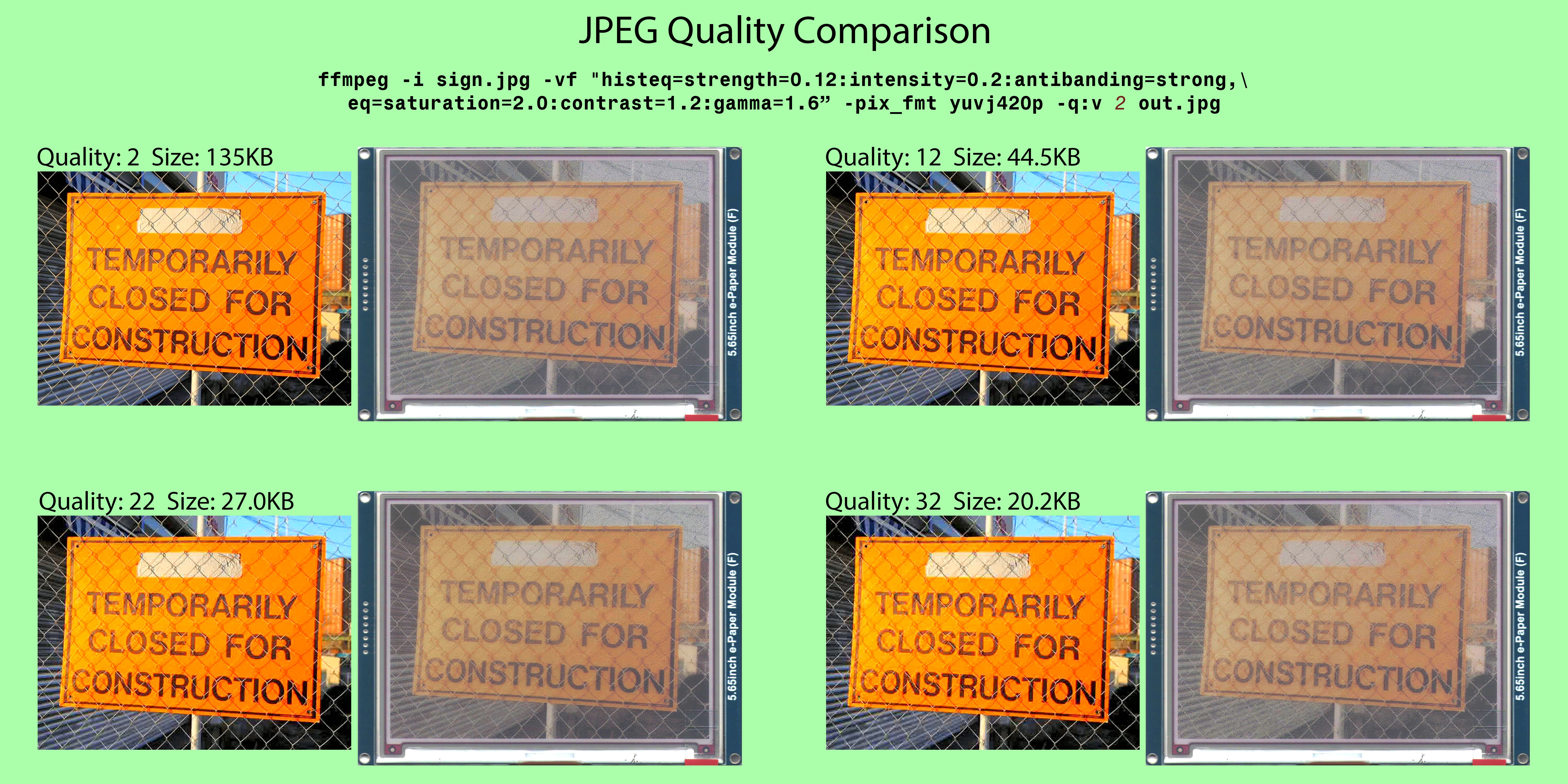
    JPEG quality test

    The ffmpeg program lets you specify how much compression to apply. The -q:v option accepts a parameter in the range 2 to 32, where 2 is the highest quality and 32 is the lowest quality. In the following test, I loaded on the display four images with different quality. The side-by-side comparison shows the compressed image on the left with the capture of the display on the right. It is noted that the quality of the overall picture is quite good even with the highest compression though the fine details are lost. This is particularly noticeable in the fence links that tend to disappear at higher compressions.

  • PCB and 3D Printed Enclosure

    Manuel Tosone03/01/2021 at 11:02 0 comments

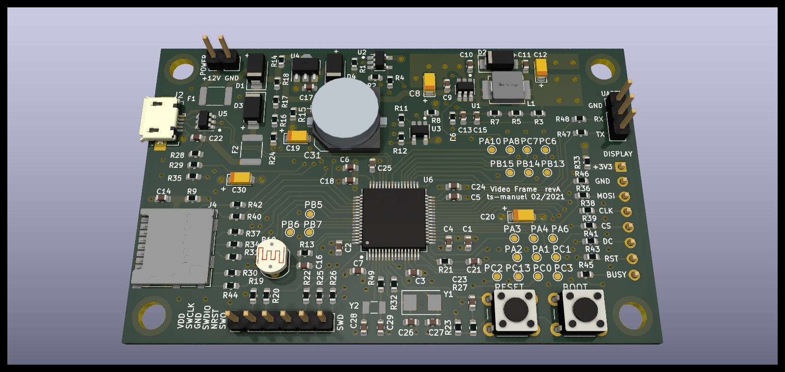
    PCB Layout

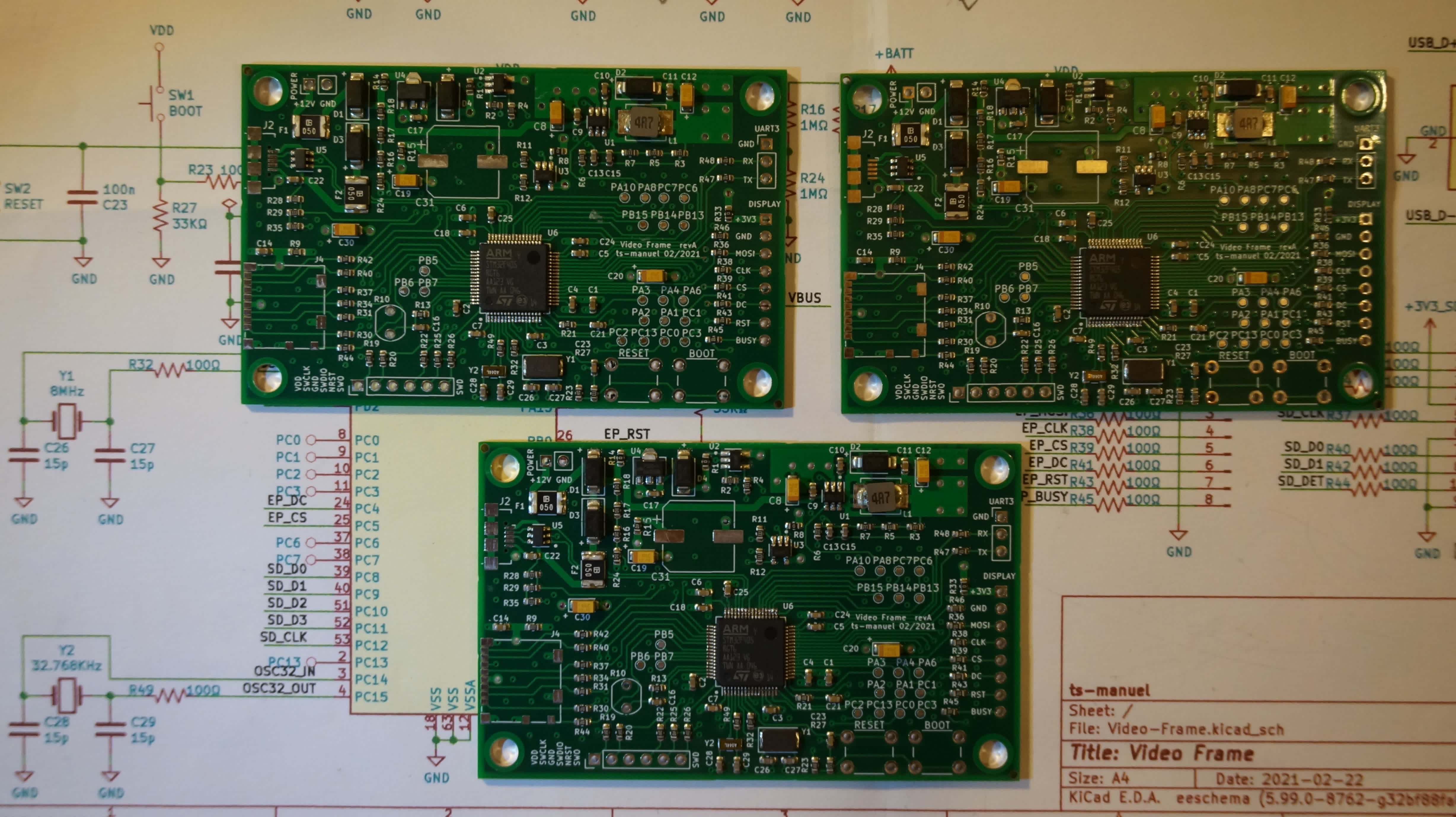
    PCB layout is done, design files are sent to JLCPCB for manufacturing and assembling.

    There is a timelapse video of the layout if you are interested.

    PCB

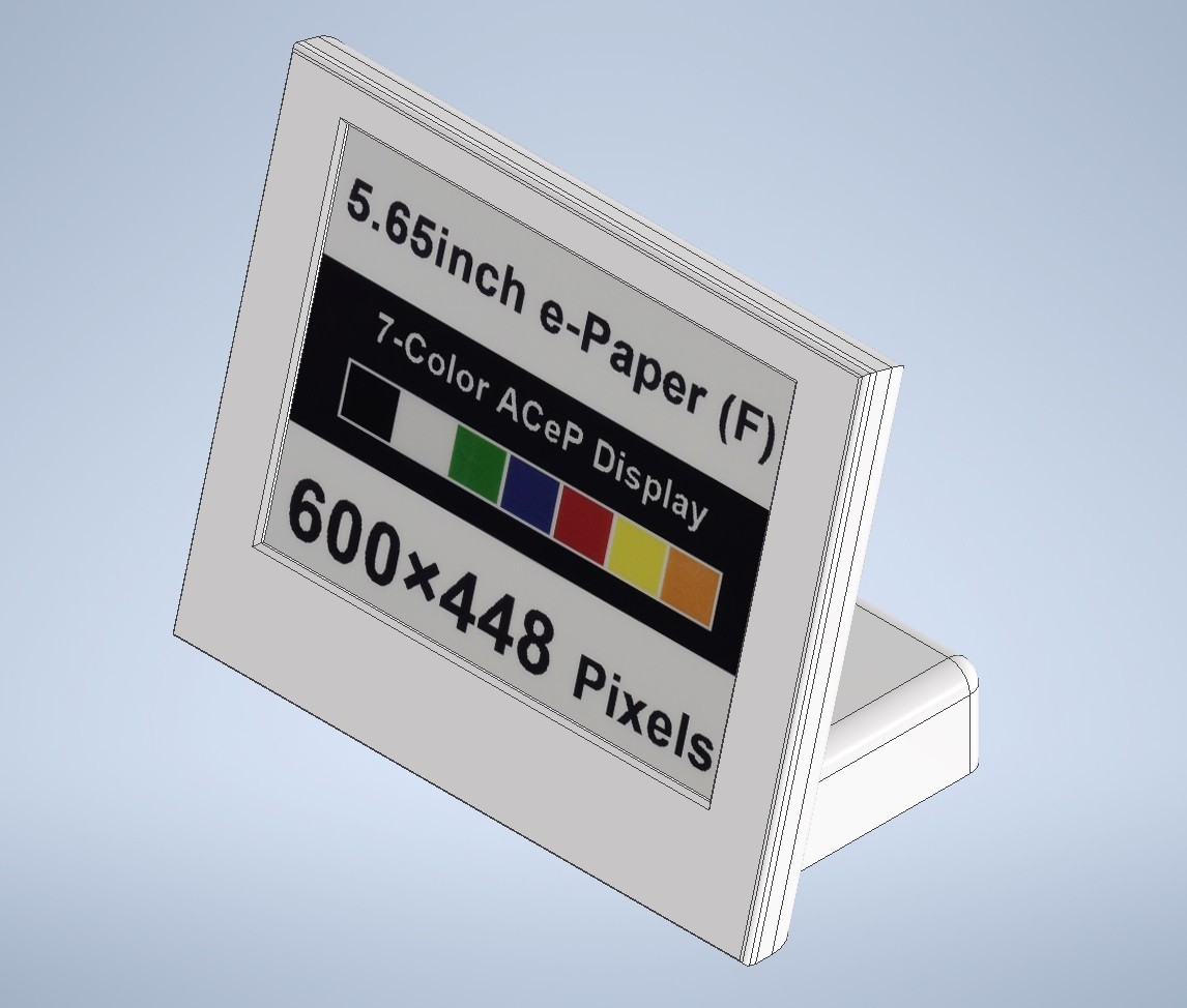
    3D Printed Enclosure

    I designed an enclosure to hold the display, the circuit board, and 6 AA batteries.

    3D Models are on GitHub. If you want to make your own, for the battery holder, you need to salvage the contacts from somewhere or you can get them from Mouser 5210 5223 5211 5201.

    The PCB is held in place by 4 M3x6 screws while the two halves are held together by 4 M3x8 screws.

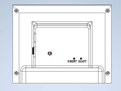
    Enclosure
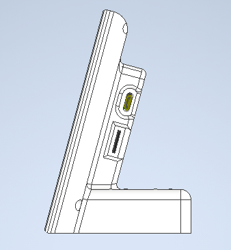
    Enclosure side
    Enclosure back

    The following video shows how the enclosure goes together.

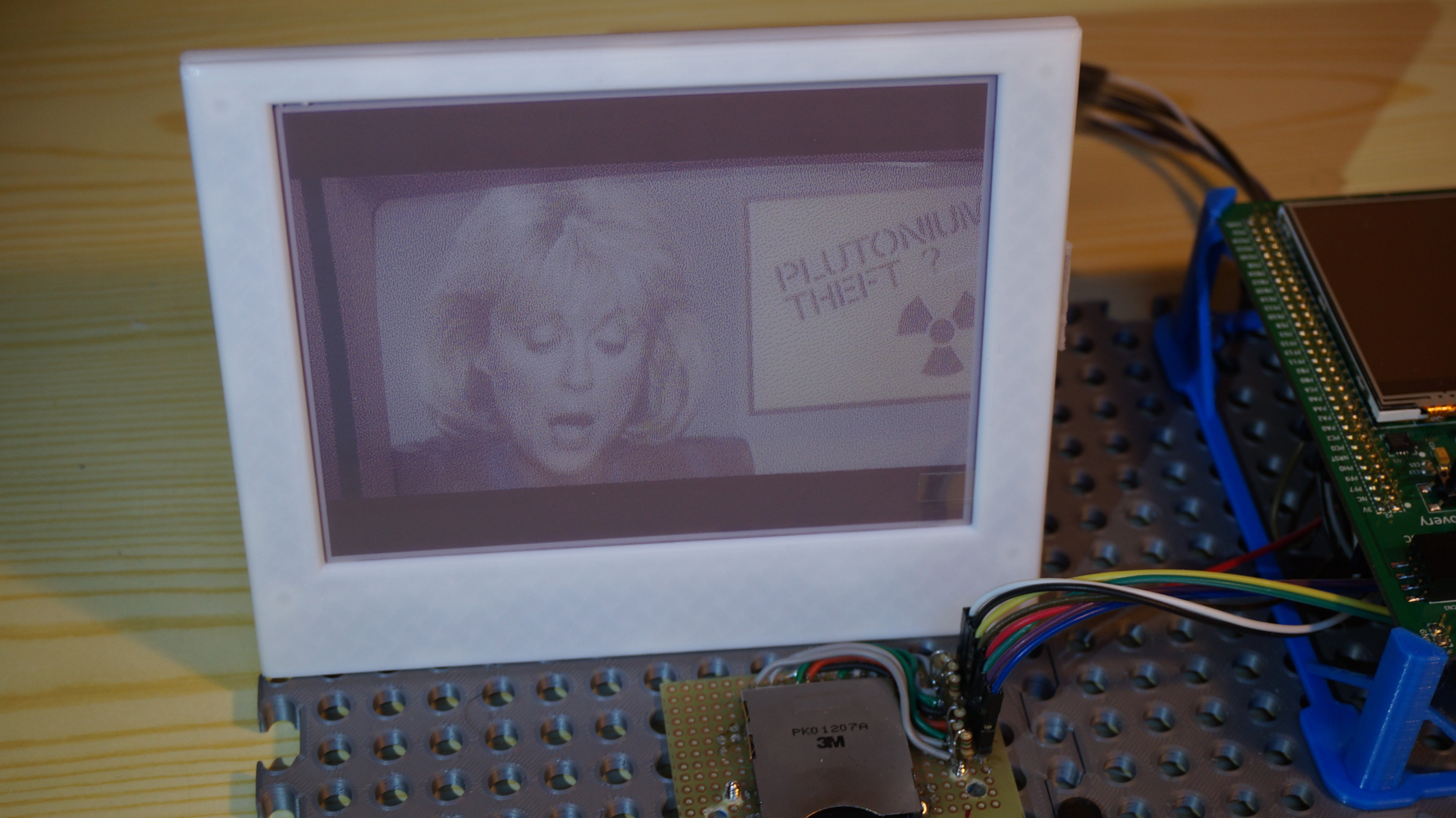
    I put the display in its case and connected it to the STM32 Discovery. Now I can enjoy a movie while I wait for the circuit boards.

  • Schematic and Power Consumption

    Manuel Tosone02/22/2021 at 13:41 0 comments

    Schematic

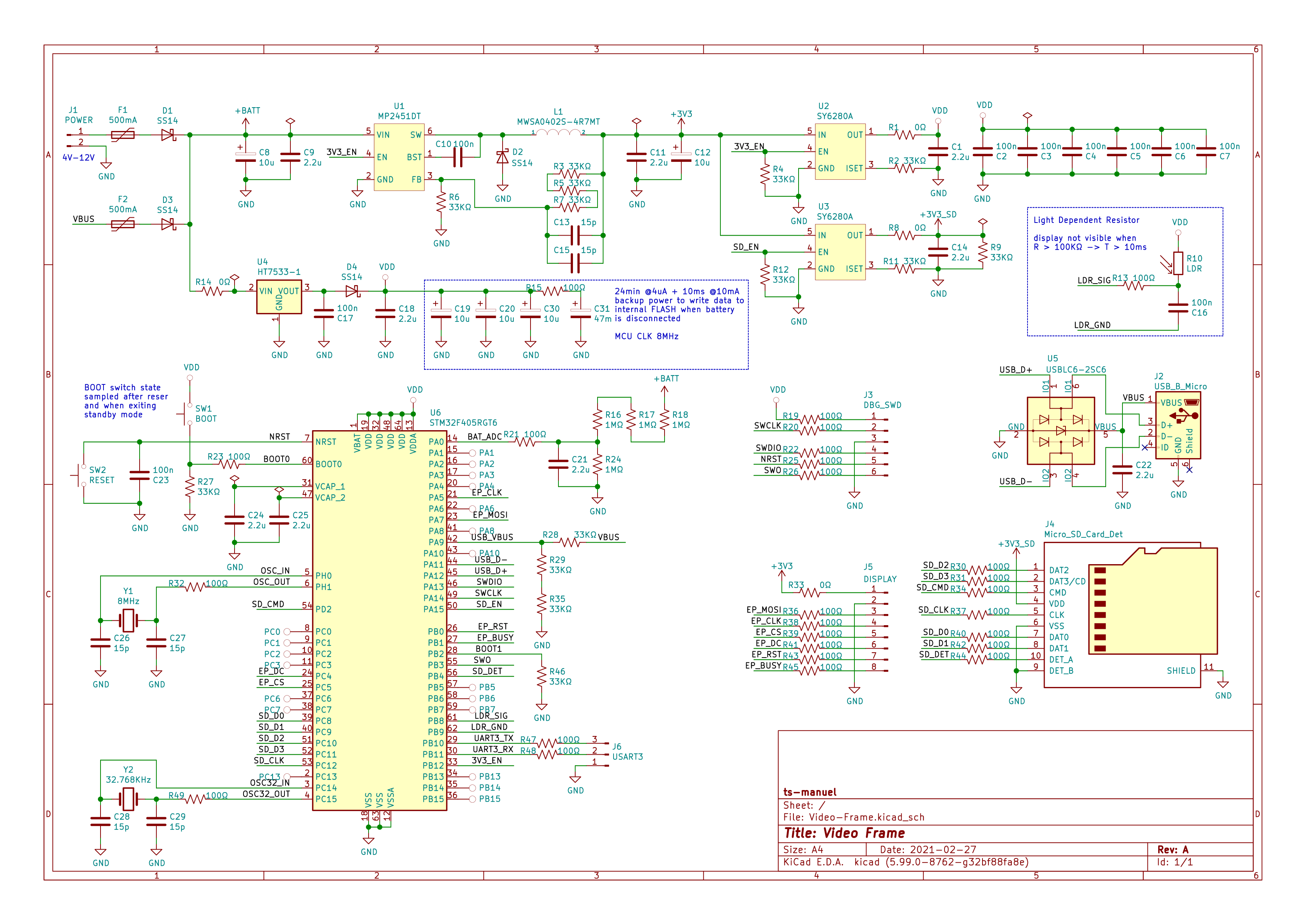
    I spent the last two days working on the schematic for the first prototype, here is what I came up with.

    I finally decided on what battery to use, the board will be powered by 6 AA. I have a design in mind for a case in which 6 AAs fit well.

    The plan is to have the board assembled by JLCBCB and so I tried to optimize the BOM.

    Power Section

    The board can be powered either from batteries or from the USB connector. The power supply is divided into two paths, there is a switching regulator and an LDO to supply power during sleep. The reason for having two regulators is that the MP2451DT DC-DC converter has an efficiency greater than 85% with a 100mA current load but, due to the switching losses, the efficiency drops drastically at low loads. The datasheet for the microcontroller states a power consumption of 4uA in Stand-By mode. The HT7533 LDO has a quiescent current of only 2.5uA. The two SY6280A are power-distribution switches. U2 switches power to the microcontroller and is used to isolate VDD from the 3.3V when the DC-DC converter is disabled. U3 switches power to the SD-Card, it is used to disable the SD-Card while the screen is busy updating to save power.

    R16, R17, R18, R24 form a potential divider that's used to measure the battery voltage. This makes it possible to detect when the batteries are running low and to display a low battery icon on the screen.

    R10 is a Light Dependent Resistor, it's used to measure the ambient light. Since e-paper displays have no backlight and are not visible in the dark, there's no point in updating the display if nobody is able to see it. An LDR has a resistance that varies with the amount of light that shines on it. The resistance varies from a couple of hundred ohms, when shining a bright flashlight on it, to hundreds of kiloohms, when in complete darkness. The way the resistance is measured is by determining how long a known capacitor takes to charge from a fixed supply voltage. This mechanism is quite clever and doesn't consume any power when the resistor is not measured.

    MCU Section

    The microcontroller is an STM32F405RG, it has 1024KB of FLASH and 192 KB of RAM plus all the required peripherals. There are two quarts crystals, the 8MHz one is the main oscillator, the USB requires an external crystal. The 32.768KHz one drives the RTC that's used to wake the microcontroller every 24 minutes to update the display.

    All unused pins are connected to test pads in case they are needed in the future.

    C19, C20, C30 in conjunction with the 47mF supercapacitor C31, provide the energy required to power the microcontroller when the batteries are removed. C31 has enough stored energy to power the microcontroller for 24 minutes in standby mode when the power consumption is 4uA. The additional 30uF of capacitance on the VDD line are enough to power the microcontroller for 10ms after it exits standby mode. This is used to store the currently displayed frame in the internal FLASH so that the movie doesn't restart from the beginning every time the batteries are changed.

    Programming the Microcontroller

    There are three ways to program the microcontroller. The first is using the SWD debug interface, the second and third methods involve the bootloader. STM32 MCUs ship with a preprogrammed bootloader that can be used to program the device, in this case, either from the serial port or through the USB.

    The MCU automatically enters into boot loader mode the first time it is powered on when the flash memory is empty. By pressing the BOOT button while performing a reset, the bootloader can be started at any time.

    Power consumption estimation

    The display updates every 24 minutes, that period of time is divided into 5 steps.

    1. DISPLAY INIT: The MCU wakes from sleep, enables the DC-DC converter, and initializes the display.
    2. DISPLAY CLEARING: During this phase, the display is busy clearing itself, the MCU is not needed.
    3. JPEG DECODE: The SD-Card is initialized,...
    Read more »

  • JPEG Decoding

    Manuel Tosone02/17/2021 at 15:53 1 comment

    The frames to be displayed will be stored on an SD-Card as a sequence of jpeg files. Considering the time it takes to refresh the display and that I want to maximize battery life, I decided to update the display every 24 minutes, showing only one every 24 frames. This will make the battery last 24 times longer. The display resolution is 600x448 and, since only one every 24 frames must be stored on the SD-Card, the storage requirement is 144MB/hour (with 60% quality). An average length of 90 minutes movie can be stored in 200MB.

    Time to implement a jpeg decoder and... I wrote my own from scratch. You see I want to learn something new with each project, this was the perfect opportunity for learning how jpegs work. The best resource that I can find on the subject is a video series entitled Everything You Need to Know About JPEG.

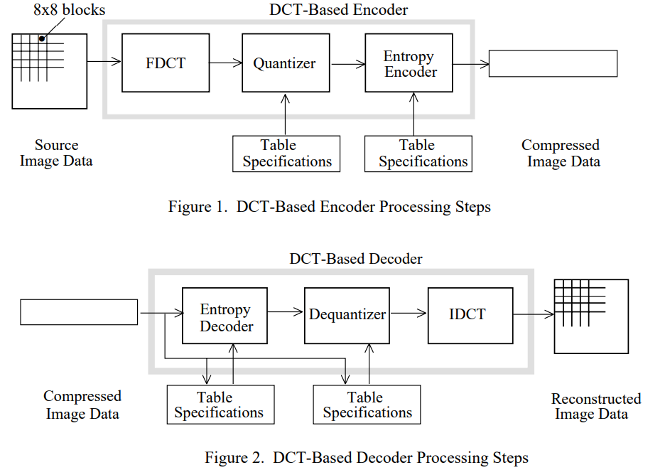
    If you are not familiar with how jpeg works here is a brief overview. The first step in the encoding process is to convert the image from RGB to YCbCr, each color component is encoded independently. Next, each color component is divided into blocks of 8x8 pixels, each block goes through to the encoding process independently. The encoding starts with the forward DCT that converts the 8x8 block into a frequency domain representation. After that, the quantization step removes high-frequency data, and then the entropy coding is used to more efficiently store the coefficients.

    JPEG Encoding/Decoding

    The decoding process works the same way only backward, it starts with the compressed data stream, the first step is to undo the entropy coding then the coefficients are dequantized and, after that, the inverse DCT returns an 8x8 block of pixels. The final step is to convert back from the YCbCr color space to RGB. 

    The tricky part is how to interpret the bytes in the file since to decode the compressed data more information is needed other than the compressed bitstream. To undo the entropy coding the decoder must have a copy of the Huffman table that has been used by the encoder and to dequantize, the decoder must have a copy of the quantization table. This information is encoded into the file and is separated by markers. Markers are two-byte codes that precede and identify a block of data.

    The implementation of a decoder on a microcontroller poses some challenges, there is not enough RAM for a frame buffer and so the pixels must be sent to the display as they are decoded. Fortunately, the way 8x8 blocks from each color component are interleaved makes this straightforward.

    The problem is that the pixels to the display must be sent in order from left to right top to bottom and the decoder produces 8x8 blocks of pixels instead. The solution is to have a small buffer, with the height of a block and the width of the screen. The decoder fills the buffer with pixels and, when it's full, it is sent to the display.

    To make the images look good with only 7 colors, before sending the buffer to the display, the Floyd Steinberg dithering algorithm is applied.

    The following video shows the display updating with some test images. It is noted that even if the display has only 7 colors, the dithering algorithm does a good job. If viewed from a couple of meters away the image looks almost perfect.

  • Display Test Fixture

    Manuel Tosone02/13/2021 at 16:25 0 comments

    Quick update on the test setup.

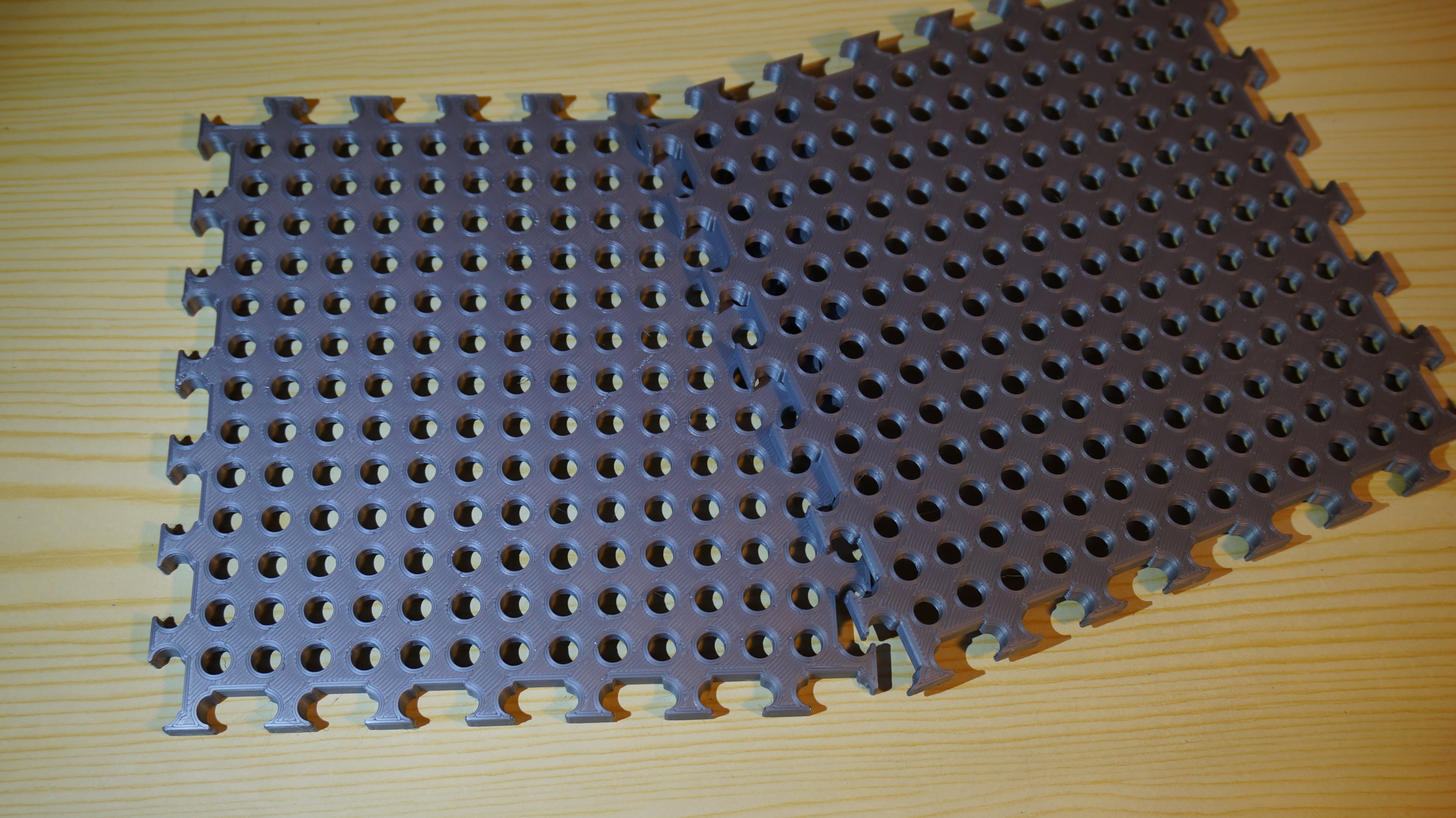
    I was tired of having the display and the development board floating around on the bench, I wanted to make some kind of a test fixture. My first thought was to 3D print something to keep it all together but I didn't want to design and 3D print a frame only to be used one time. The idea I came up with is to have a perforated base on which all the components are placed. The advantages of this are quite obvious, it is possible to rapidly move components around and it can be reused for future projects.

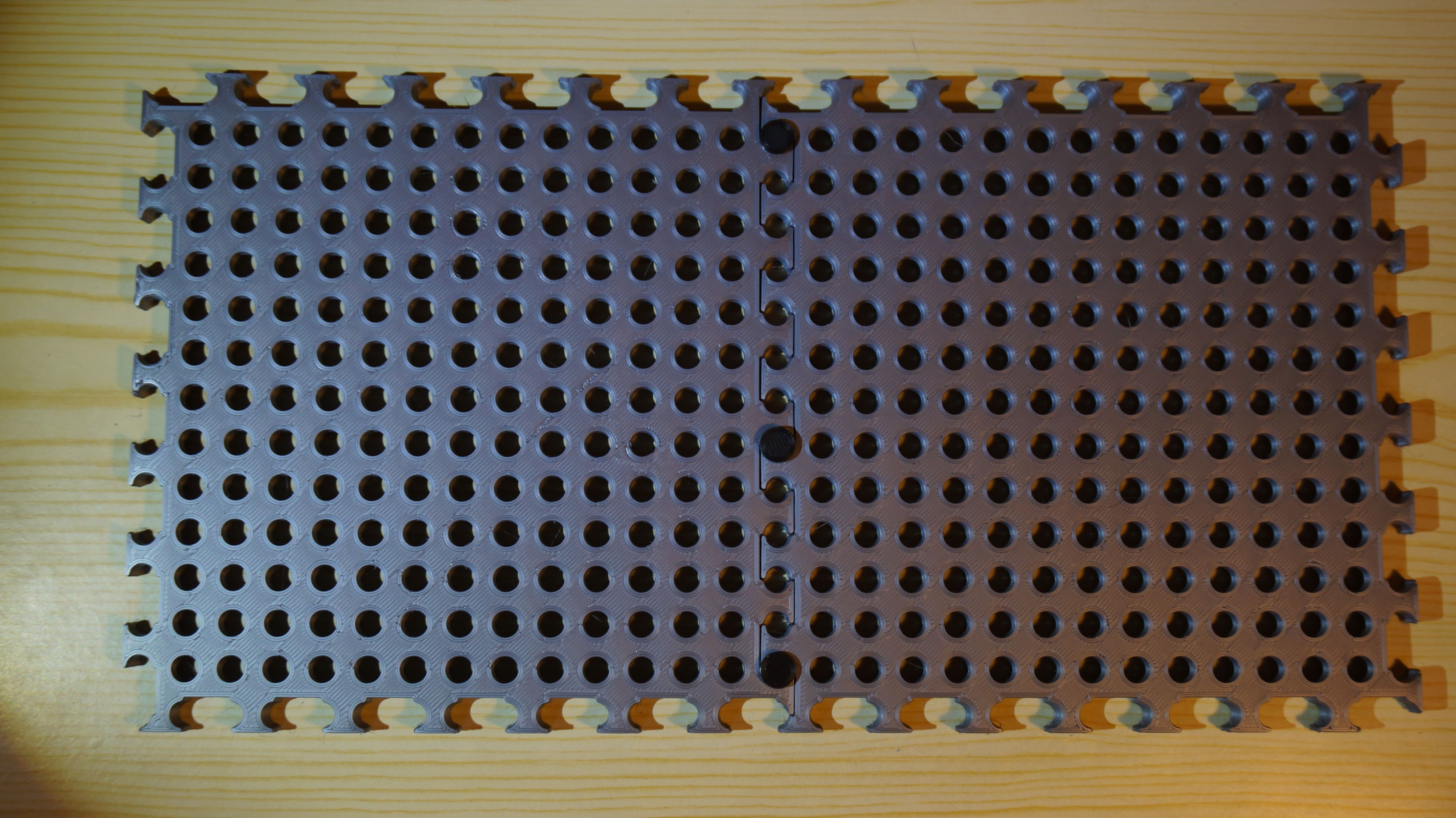
    The base is made of squares that can be joined together. Each square has a 15x15 grid of 6mm holes. The spacing between holes is 10mm

    The squares are joined with round pins.

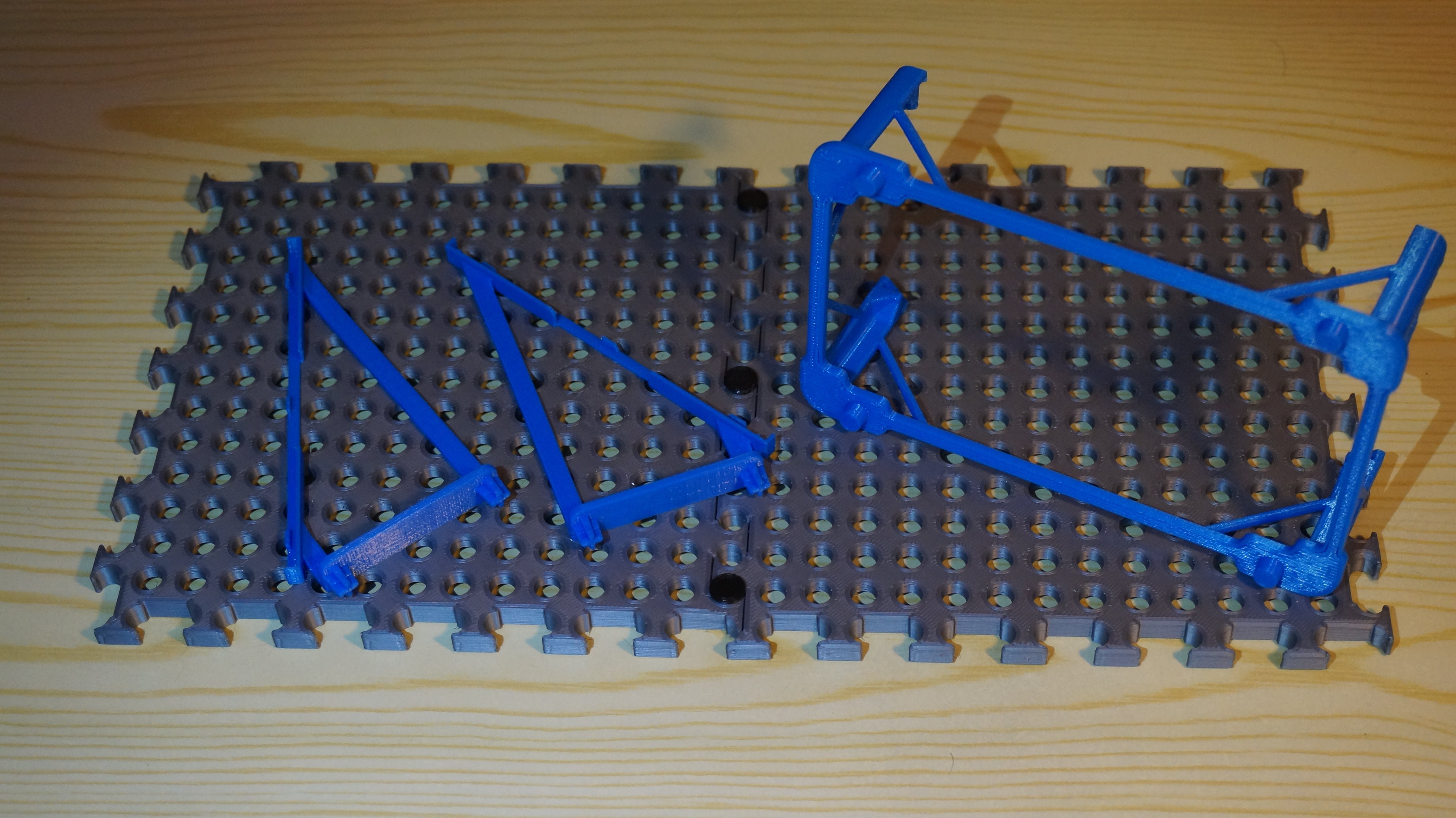
    The display and the discovery board are kept in place by holders with pins on the bottom.

    The 3D models for this test fixture are available on this site. If you like the concept, feel free to use it for your own prototypes. For now, I only printed a holder for the discovery board, in the future I'll make holders for the boards that I'm working on.

    The following video shows the display mounted in the test fixture, as it goes through some test patterns.

  • Display Testing

    Manuel Tosone02/06/2021 at 19:13 1 comment

    Power Consumption

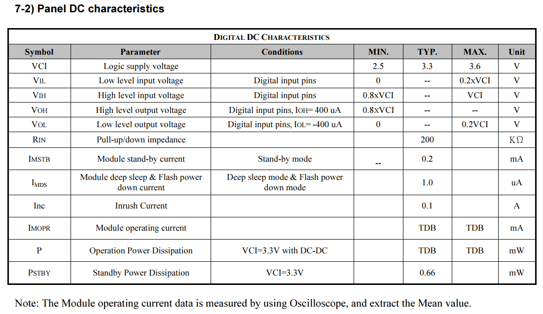
    Being this an ePaper display, it draws power only when the image is changing. When the display is in deep sleep mode, the datasheet gives a typical current draw of 1µA but it doesn't say anything about the power consumption during an update. The only thing it says is that the inrush current is 100mA. I guess that means that when the display comes out of reset and powers on it will draw up to 100mA, but that's not what I'm looking for, I want to know how much energy it takes to update the display.

    Panel DC characteristics

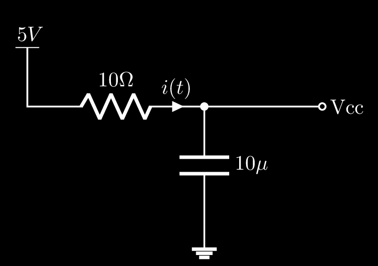
    To measure the current waveform, as the display is updating, I put a small resistor in series with the power supply and measured the voltage drop with an oscilloscope.

    Display test circuit

    The diagram on the left shows the test circuit.

    The datasheet specifies a typical inrush current of 100mA, with a  10Ω resistor the voltage drop will be 1V living enough margin. Plus having the resistance power of 10 makes the maths easier.

    Energy is measured in Joules 1[J] = 1[W]*1[sec], to compute the energy is just a matter of integrating the power over time.

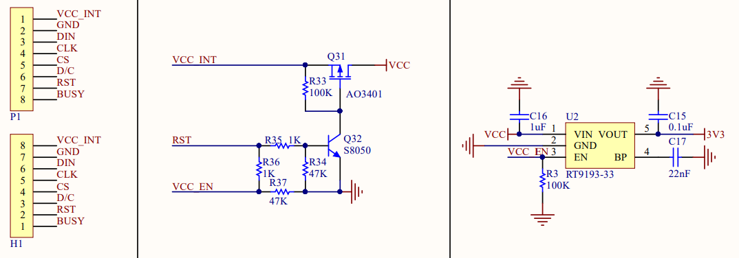
    The breakout board for the display has an integrated LDO that regulates the input voltage to 3.3V. The quiescent current for the LDO is 130µA, it is so low that can be ignored, the current flowing through the resistor should be almost identical to that flowing into the display. In the final application, the display will be powred from 3.3V thus it is important to use 3.3V in the formula above otherwise we are taking into account the power that is dissipated by the regulator.

    Display power supply
    Display breakout board power section

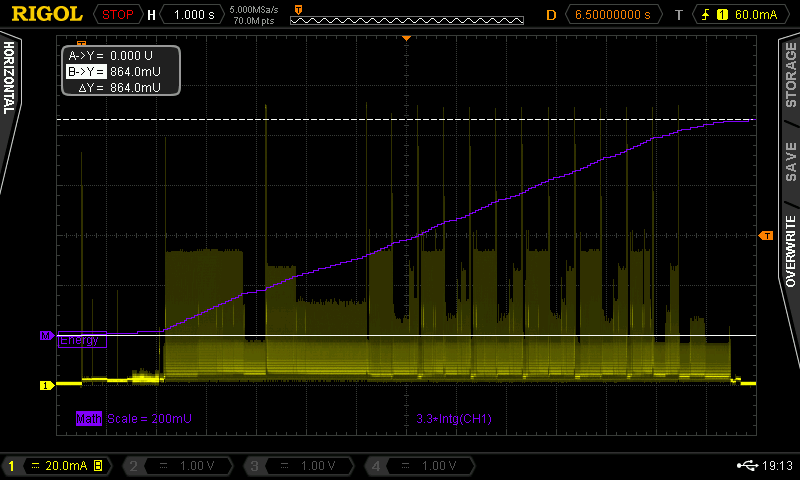
    After connecting the oscilloscope I was able to capture some waveforms. Note that the scale is 20mA/div, I'm using a 1x probe across a 10Ω resistor, setting the probe multiplier on the oscilloscope to 0.1x makes it possible to read the current directly without conversion. It is also noted that the display draws current in bursts as it goes through the update sequence.

    Display update current

    display update current waveform


    Here is a video showing the update sequence. It is noted that as the display updates, it goes through more than 7 colors. Maybe it's possible to modify the lookup tables to increase the available colors or to change the displayable colors. Sounds like a future project ;)

    The datasheet specifies two test patterns, one for the typical and one for the maximum power consumption. To make it easy to display different patterns quickly, I wrote a simple command parser on the STM32 that listens for commands from the serial port and updates the display accordingly.

    Display test waveforms

    Typical Power Consumption

    The typical power consumption is measured as the displayed image changes from full white to the colored horizontal stripes shown in the picture above. Using the maths function of the oscilloscope it's straightforward to integrate the current during the update cycle. Using the cursors the total energy required is determined to be 0.864J.

    Maximum Power Consumption

    The maximum power consumption is measured as the displayed image changes from full white to a sequence of horizontal black and white lines. Applying the same procedure as above, the energy required is determined to be 1J.

    Conclusions

    The typical and maximum energy required to update the display are respectively 0.864J = 240µWh and 1J = 278µWh.

    To wrap this up let's now roughly estimate how many update cycles we can get out of a battery. Since the rest of the circuit is not designed yet let's assume for now that the display is the only load. Let's also assume that we have a 2000mAh battery whose voltage is 3.3V. The energy stored inside the battery is

    Since the display uses 1J for each update the total number of updates is 23760. The display will be updated once every 24 minutes so the total run time is 23760 * 24 min = 396 days. This is in the ideal case where only the display draws power and at least shows that this display is...

    Read more »

View all 9 project logs

Enjoy this project?

Share

Discussions

Hester Graham wrote 12/01/2024 at 13:20 point

This project with the 7-Color E-Paper display is fascinating, offering a completely different way to engage with movies, playing each frame one minute at a time. The low power consumption of E-Paper is perfect for a setup like this, where you want the device to last for months. It really highlights how innovative tech can transform the viewing experience, turning even a movie into something more meditative. If you're into creative digital experiences like this, you might want to explore https://apkloklok.net/loklok-web/ – it's another cool platform that brings new ways to enjoy movies and series with unique features and user-friendly access!

  Are you sure? yes | no

christopherhicks2 wrote 01/17/2024 at 12:47 point

The Slowest Video Player with 7-Colors introduces a unique experience, resembling a digital picture frame. This unconventional player plays movies at an incredibly slow pace, unveiling each frame at a leisurely rate of one per minute. The deliberate approach allows viewers to savor every detail, creating a distinct and contemplative cinematic experience. If you're looking for an alternative and unhurried way to enjoy your favorite films, this could be a captivating choice. By the way, have you tried loklok for pc windows 11 .It's another interesting addition to the digital experience, seamlessly integrating with the latest Windows platform for an enhanced user interface

  Are you sure? yes | no

amaly2788 wrote 10/05/2022 at 13:34 point

hey, to check out more about the component you have to check film creation interaction can be isolated into incalculable moves toward taking a film from an idea to a completed piece. In any case, there are three key stages that occur in the creation of any film: pre-creation, creation, and after-creation. ดูหนัง

  Are you sure? yes | no

diadatp wrote 04/09/2021 at 20:13 point

If this is the same display as the Pimoroni Inky Impression (https://shop.pimoroni.com/products/inky-impression), then the controller is the UC8159. The datasheet can be found on Google.


What's really interesting is that the controller can probably display more than seven colours with some clever firmware tricks. Have a look at this work by Dmitry, who managed to double the colours on the more common red/white/black display.

https://twitter.com/dmitrygr/status/1380019278661881857

  Are you sure? yes | no

Manuel Tosone wrote 04/11/2021 at 16:39 point
Yess!!! It is the UC8159 controller.

By playing around with the registers I was able to modify the lookup tables.
Bit 7 in the second byte of the Panel Setting register switches between external FLASH and internal SRAM for the LUTs.

The display is definitely capable of more than seven colors. The controller is limited to 8 colors for every update, but it should be possible to switch LUTs between updates to get more colors.

  Are you sure? yes | no

Manuel Tosone wrote 02/20/2021 at 08:41 point
Thanks for the suggestion @Wayne but the problem is that this display doesn't support partial updates. The documentation provided by Waveshare states that the display must be completely cleared before every update.

The documentation doesn't specify what controller is used in the display, searching the internet I found that it can be an IST7106 but I can't confirm it because the datasheet is not available.

  Are you sure? yes | no

Giovanni wrote 02/17/2021 at 18:09 point

Nice project! Glad to see the power consumption measured. 

  Are you sure? yes | no

Mike Szczys wrote 02/16/2021 at 15:57 point

I loved seeing @CNLohr build that color photo fame. Looking forward to where you go with this one.

I wonder if the refresh rate will be sufficient for 1 frame per minute? My slow movie player is still going (and I have some larger panels for a future upgrade) but I'm thinking of going to refreshing the frame every 24 minutes so there's not quite so much blinking.

  Are you sure? yes | no

Manuel Tosone wrote 02/18/2021 at 08:22 point

I was thinking the same thing, to refresh the display every 24 minutes, displaying only one every 24 frames. This will make the battery last 24 times longer. The update process takes roughly 30 seconds because the display must be cleared completely between every frame to prevent ghosting.

In the interest of increasing battery life, I'm thinking of implementing a light sensor to update the display only when it is visible and to use the RTC inside the microcontroller to stop updating the display at night.

  Are you sure? yes | no

Ahron Wayne wrote 02/19/2021 at 03:14 point

Have you considered preprocessing to avoid completely refreshing each time? I am thinking that if part of the scene remains static you could skip that area. Before uploading the frames you would run something like this on each adjacent one: https://stackoverflow.com/questions/53640752/how-to-find-all-shared-regions-between-two-images/53652807

  Are you sure? yes | no

Similar Projects

Does this project spark your interest?

Become a member to follow this project and never miss any updates