 Vipin M
-
1Assemble the grip
- Start by inserting the 1/2" PVC conduit into the top portion of the grip, through the handle and in to the bottom portion of the hammer head. There are 2 distinct benefits of using a PVC pipe. It adds a lot of strength on the slender portion of the assembly and reduces the 3D printing time.
- Insert the DC motor into the top portion of the grip. Use a pair of wire long enough to extend from the motor all the way to the hammer head.
- Secure the DC motor to the grip using 30 mm long M3 screws.
- Insert shaft extension into the motor axle on both sides.
- Securely attach the wheels to the shaft extension.
- Use the small 3d printed tabs to attach the top and bottom portion of the grip.
-
2Assemble the head
- Mount the L298N motor driver on the 4 standoffs in the electronics mounting platform using M3 screws.
- Attach the MPU6050 accelerometer/gyroscope sensor using the 2 holes in the center. This minimizes any offset when the hammer is in the vertical position.
- The microcontroller (Arduino Nano) and the Bluetooth module (HC-05) go on the other side of the MPU6050 ensuring a relatively uniform weight distribution. Ensure that the micro USB port of Nano lines up with the opening on the side of the upper portion of the hammer head.
- Secure the battery holder to the battery mounting platform using the 2 standoffs.
- Insert the switch through the designated opening in the lower portion of the hammer head.
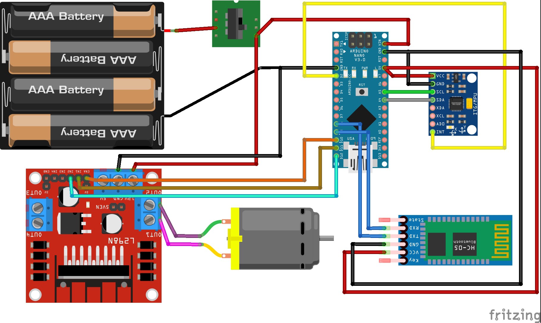
- Complete the connection as per the circuit diagram below.
- The upper portion of the hammer head has slots for 4 M3 nuts. Line up the slots and join the upper and lower portion of the hammer head using 4 M3 screws.

-
3Power on
- Place the hammer on a flat surface in the vertical position.
- Turn the switch on and enjoy!
Enchanted Thor Hammer
"Whosoever balances this hammer, if they be worthy, shall possess the power of Thor..."
Discussions
Become a Hackaday.io Member
Create an account to leave a comment. Already have an account? Log In.