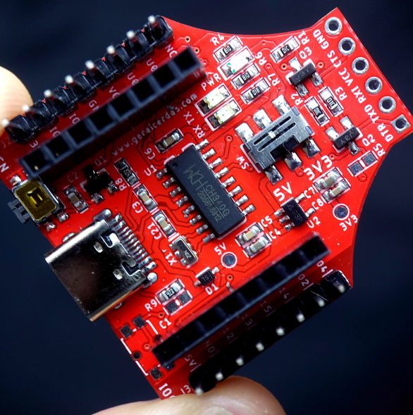
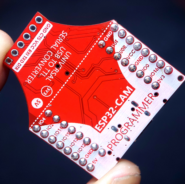
This is my initial design. It based on Bitluni's Cam-Prog (https://bitluni.net/camprog) with some modifications. There are two main parts of the schematic. First, is a common auto-program for ESP32 / ESP2866 which is control GPIO0 and RESET of ESP32. And second, is a N-Channel MOSFET to turn-on and off the ESP32 for replacing the function of RESET, since the developer forgot to breakout the RESET pin.
Please take a look the github link for this project. It contains PCB schematic and board layout in Eagle format. Also there are a Bill of Materials and production file in gerber format. Simply send the gerber file to your pcb manufacturer like pcbway, jlcpcb, or other local pcb manufacturers. Most of components are 0603 package, so it's able to solder by hand.
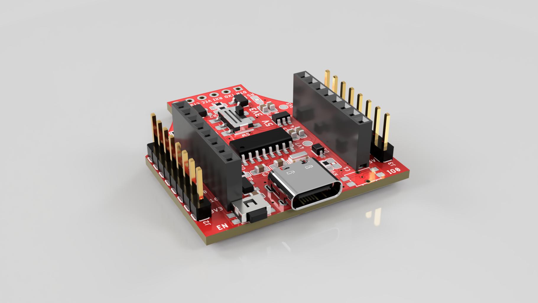
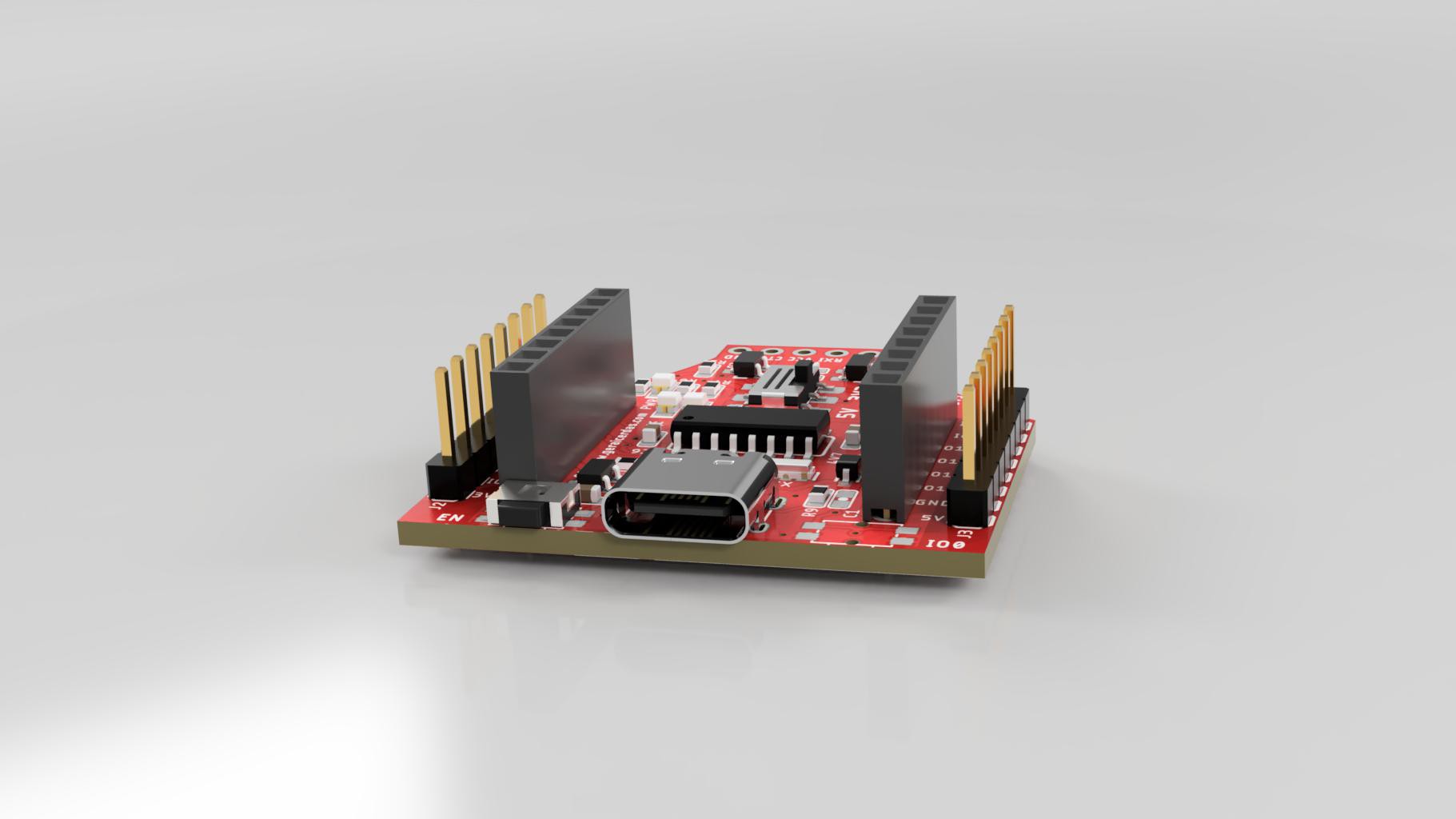
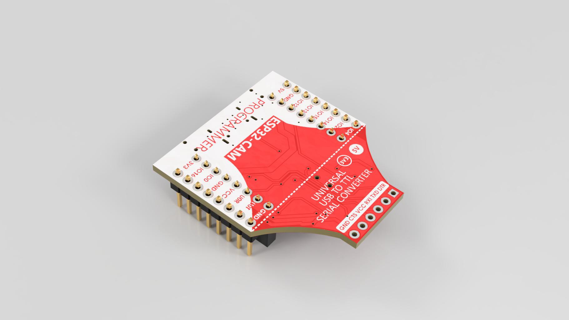
For some one who needs the 3D model of this design, please take a look my grabcad link for this project : ESP32-Cam Programmer | 3D CAD Model Library | GrabCAD
Hope this helps.
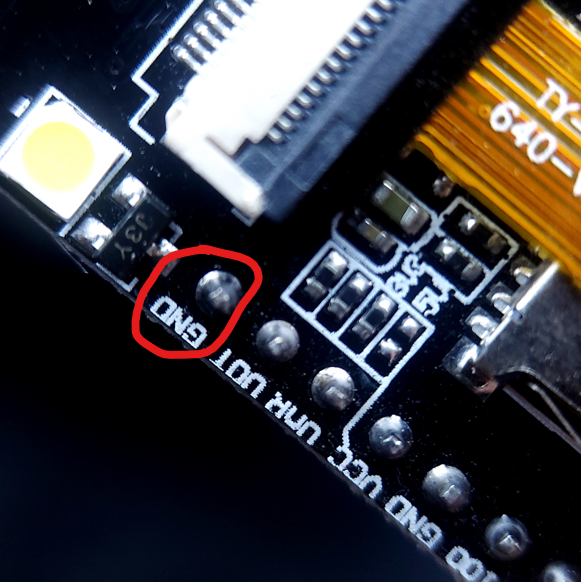
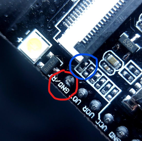
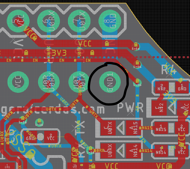

Thank you for this! I didn't notice the reset button on my newer esp32-cams and thought my programmer was broken, but I just had to connect it to a real ground connection...