The core design is simple - a PIC 16LF18326 microcontroller, the MS5607 sensor, and Display Visions' EA DOGM081W-A integrated LCD/controller tied together with SPI. But, the implementation turned out to be a humbling experience. Most of my work is with switching power supplies where the goal is to mitigate losses while dealing with high current, temperature, and voltage. A design powered by a 3V lithium coin cell is the opposite side of the coin and the objective remains the same: minimizing losses, in this case to maintain performance and extend battery life.
The problem is exacerbated by the battery's temperature dependent impedance. At mid-life with an ambient of 21C it is greater than 10 ohms. Drop the temperature to 0C and the impedance jumps to ~ 20 ohms with a nominal voltage of 2.7V.
This was a huge problem in the initial design. LCD options were limited because of the requirements for digit size and to be ambient readable without a backlight while optionally supporting. Display Visions was one of the few OEMs with a 3.3V LCD that met these requirements. The catch is that it does not work below ~ 2.8V, so a charge pump & LDO are used to maintain a stable supply voltage throughout battery life and across the operating temperature range.
I built a breakout board version of the charge pump design and validated it with the prototype before incorporating.
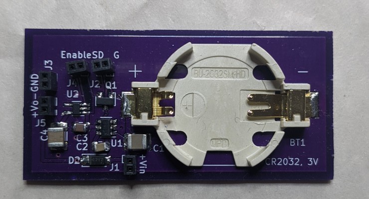
I've included the Kicad files for this as well for anyone that wants to experiment.
Discussions
Become a Hackaday.io Member
Create an account to leave a comment. Already have an account? Log In.