-
1Wiring Power Supply and Brushless Motor
-
2Wiring Encoder (example AS5048A PWM interface)
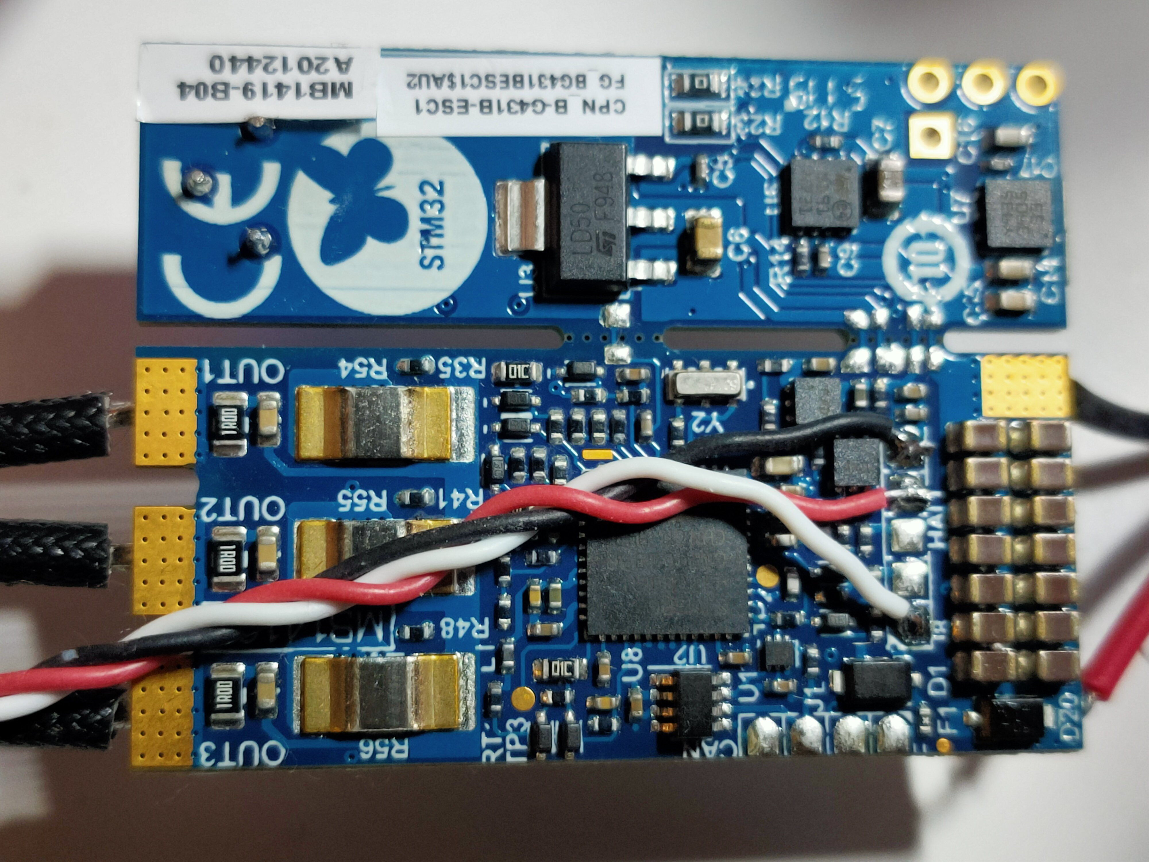
The Discovery kit embeds the hardware circuit for encoder sensor. A supply voltage
line is provided with 5 V and GND lines in J8 solder pads. Solder encoder leads on +5V, GND and one PWM input capture pad (A or B).![]()
-
3Load servo control firmware into the STM32G431 using the USB daughter board
B-G431B-ESC Brushless Servo Controller
Ultra low-cost controller for brushless servo based on the B-G431B-ESC1 Discovery kit by ST
 pat92fr
Discussions
Become a Hackaday.io Member
Create an account to leave a comment. Already have an account? Log In.