Shane Hooper
-
Upgraded Z-Axis Stepper Motor Mounts
05/23/2022 at 03:36 • 0 comments -
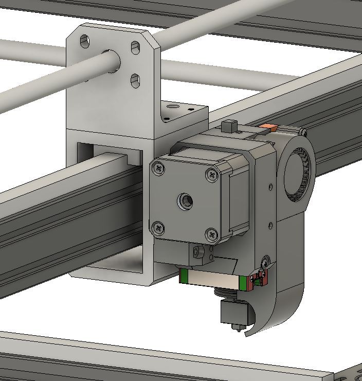
X-Carriage Design
10/05/2021 at 07:06 • 0 commentsWorkHorse 3D Printer X-Carriage Design
![]()
The Workhorse Gantry and Carriage design is a heavy-duty solution for lead screw/ball screw motion. I have a newer design that's a little lighter but I haven't tested it out yet.
X-Carriage Assembly
![]()
X and Y-Carriages use 4 M3x6mm Screws
- X-Carriage (X-Axis) 2pcs
- Y-Carriage (Y-Axis) 1pc
- M3x6mm Screws 12pcs (4 for each Carriage)
![]()
The x-axis carriage screws down to the 2040 Y-axis extrusion and rail. *Note* The y-axis 2040 extrusion must have hand tapped M5 threaded holes.
X-Carriage Design Diagram
Linear Rails
The Workhorse Printer uses MGN12H linear rails with a 20mm x 20mm Hole Pattern.
Igus Lead Screw Drive Mechanism
-
Y-Carriage Design Update
02/27/2021 at 03:04 • 0 comments![]()
- Reduced the weight and footprint of the Y-Axis Carriage.
- Experimenting with Igus anti backlash lead screw nuts.
- Trying out different direct drive extruder designs
I'm considering making the X and Y-axis C-Carriage designs from solid rectangular bar instead 2" x 4" aluminum tubing. There will be a increase in wasted and machine time but the over all weight and footprint will decrease. The more compact design will allow faster printing speeds due to reduced deflection within the system.
Large DIY 3D Printer With All Lead Screw
Large DIY 3D Printer Build: All Lead Screw 3D Printer With Fixed Bed / Moving Gantry