Making a solid state relay using mosfets isn't particularly easy.
A mosfet is turned on by applying either a positive or negative voltage (depending N/P-channel) between their gate and source. But when using them as a relay, the voltage applied to their source can vary widely. From positive to negative in quite a large range. Especially in amplifiers where I want to use them their source voltage is constantly dancing up and down.
So just applying a fixed voltage referenced to the same supply ground as the source you are trying to switch off is not possible. Your gate-source voltage would constantly change making it impossible to switch on the mosfet constantly and not damage it.
What we need is a separate voltage source which is fully independent from the one we are trying to switch off. This way we can connect the "ground" reference of this voltage source to the source of the mosfet. That way the gate voltage of the mosfet is referenced to the varying source voltage and thus fixed.
One easy option to have a separate voltage source, is to just make a second supply using a battery or a transformer. But just to drive some mosfets this is a rather expensive solution. And batteries get depleted meaning you will have to replace them.
Rod Elliott explores many options to make an isolated driver to control the mosfets. From using an isolated DC-DC converter to capacitive coupling. Many of these are interesting and good options. But the last one that was added really had my attention. It uses one single chip from Silicon Labs that does everything for you.
The Si8751 is rather cheap and only requires few external components. With this chip the only thing we need is some additional circuitry to do the detection of a DC-bias and we are set!
On the internet there are a lot of detection circuits available. After some research I've settled for one with a diode bridge and a low pass filter. A simple transistor is used to pull down a 5 V signal once the DC-bias is high enough.
The low pass filter is dimensioned for a cut-off frequency of 0.16 Hz. This should be more than low enough for an amplifier with very low bass.
The following image gives a simplified representation of the circuit when a positive voltage is applied at the input terminals.
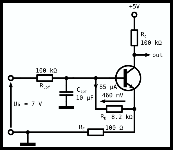
The base-emitter resistor determines at what DC-bias the transistor will switch on. Once there is 460 mV (I determined this experimentally) across its BE junction it fully turns on. The following equation is used to calculate the BE resistor:
If we have an 8 Ω speaker, there is around 875 mA flowing through the speaker. This gives a dissipation in the speaker of around 6.125 W. This switch off point might be too low, but we'll see what it gives in practice.
 Tijl Schepens
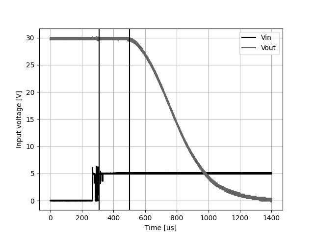
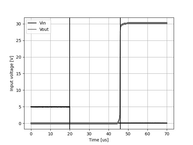 This measurement yields that the Si8751 switches off the transistors after 26 us. This is in line with the specified maximum of 35 us in the datasheet.
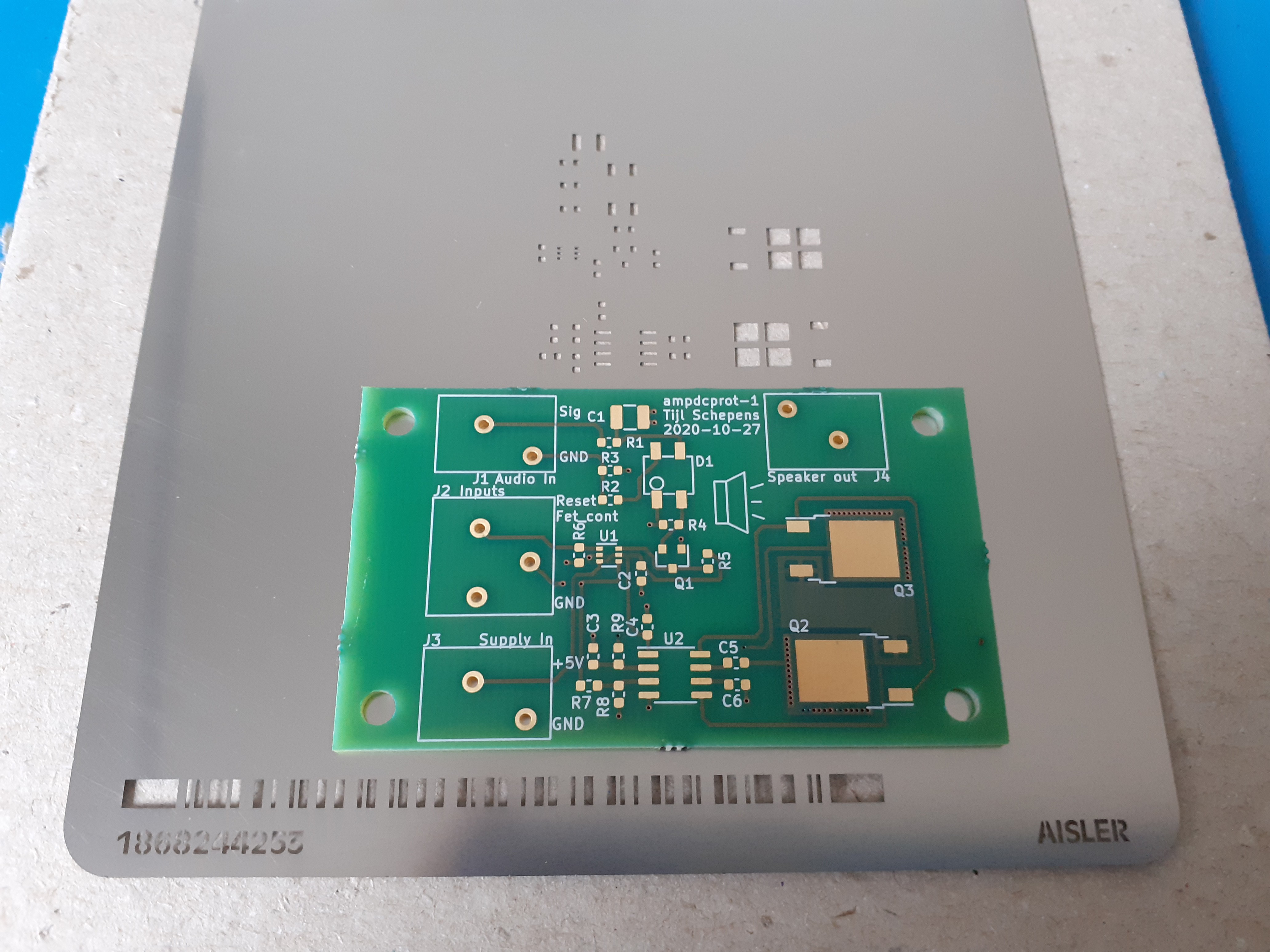
 After receiving the PCBs and components from the good people at
 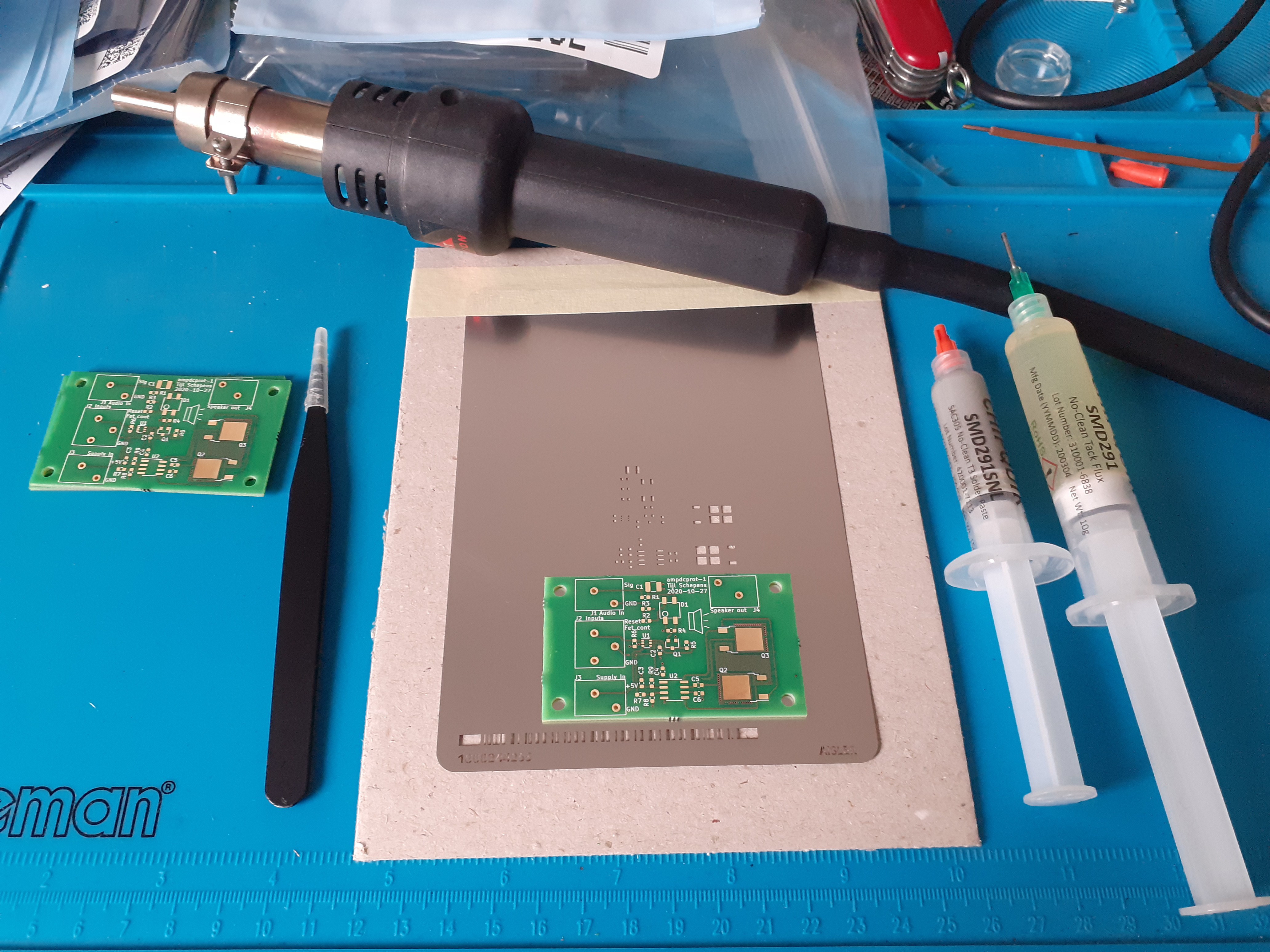 Applying solder paste and reflowing everything.
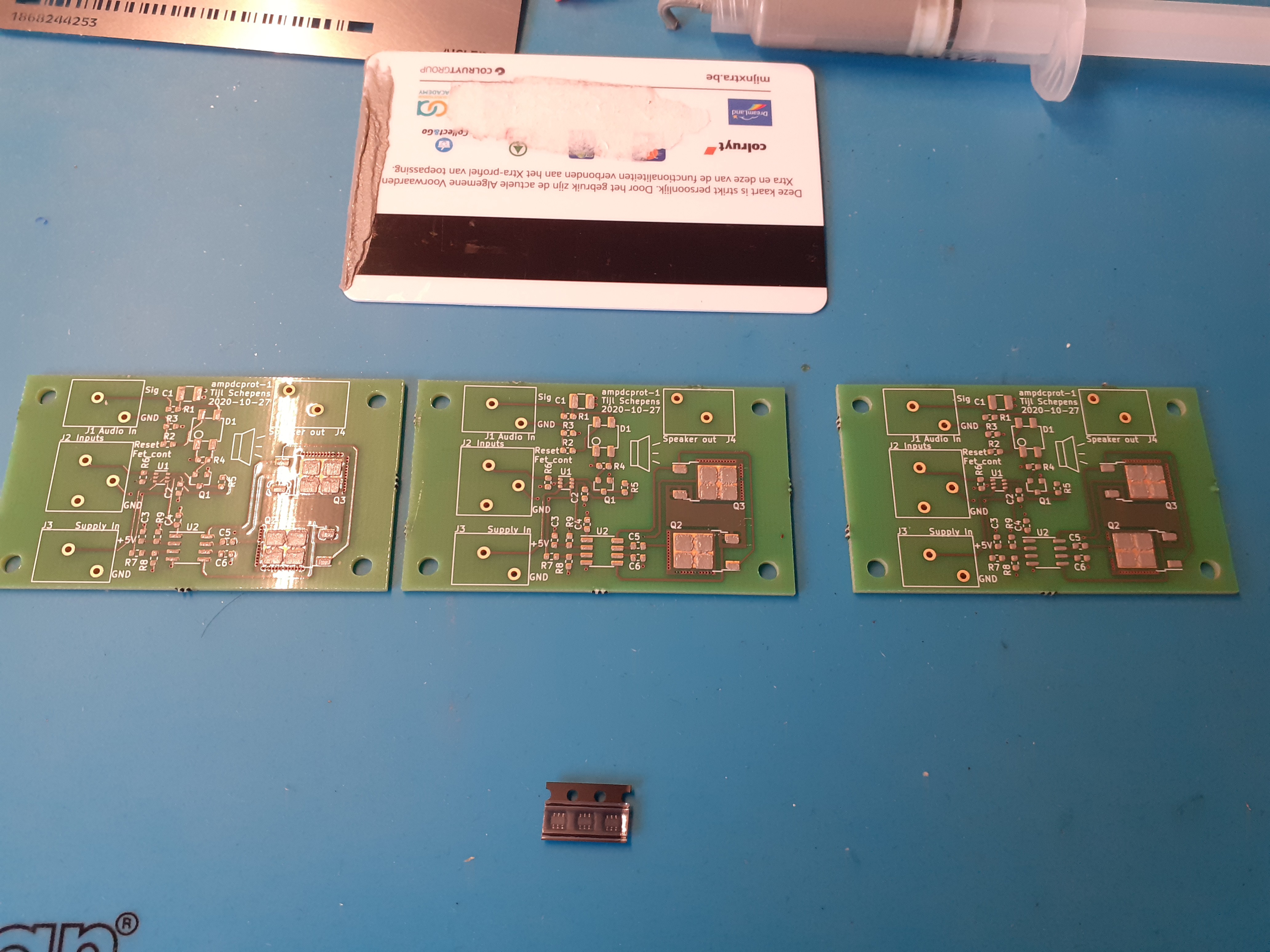
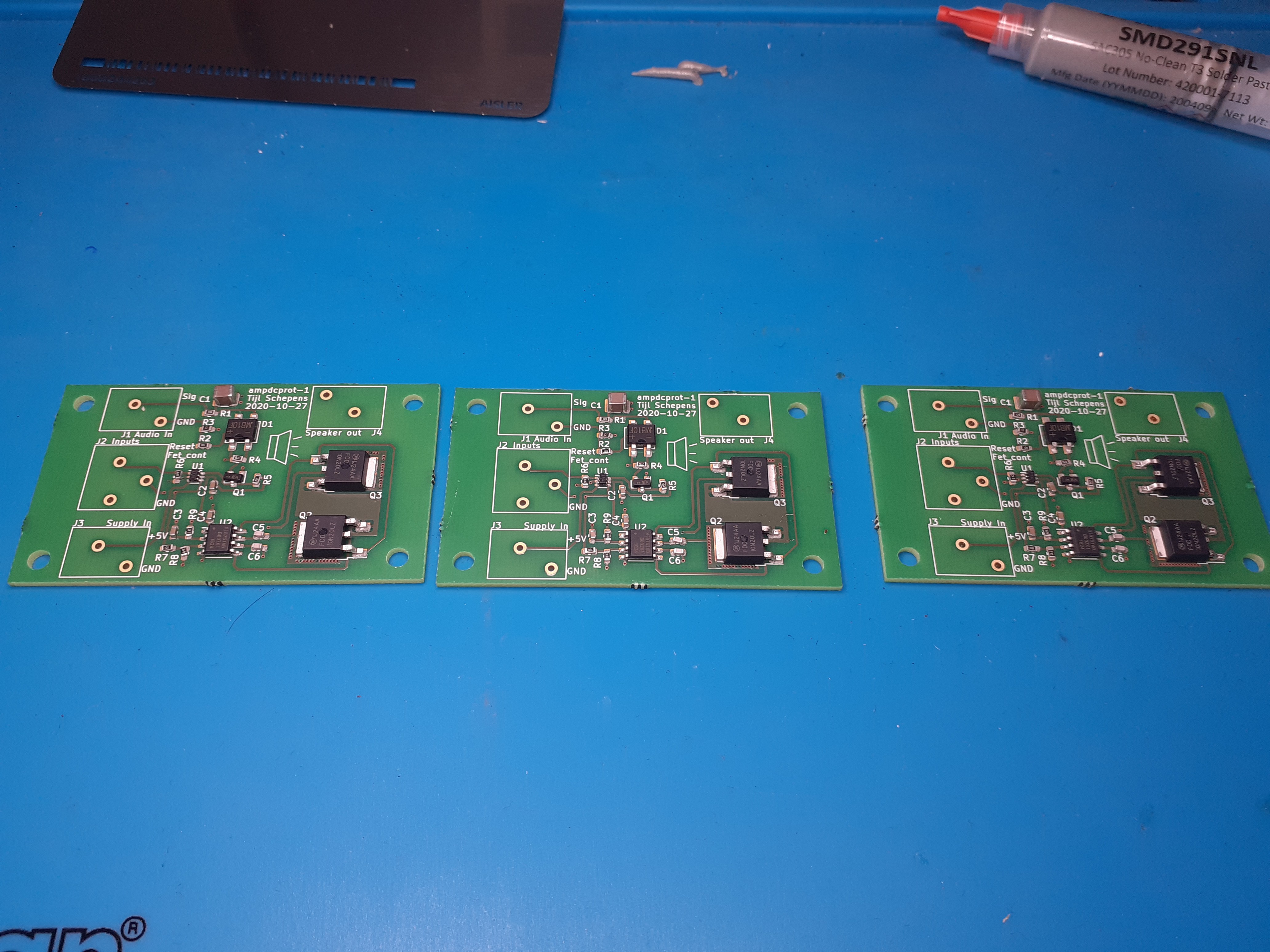 For the connectors it seems that I made a mistake. I think I ordered the wrong ones as my footprint matches the datasheet.
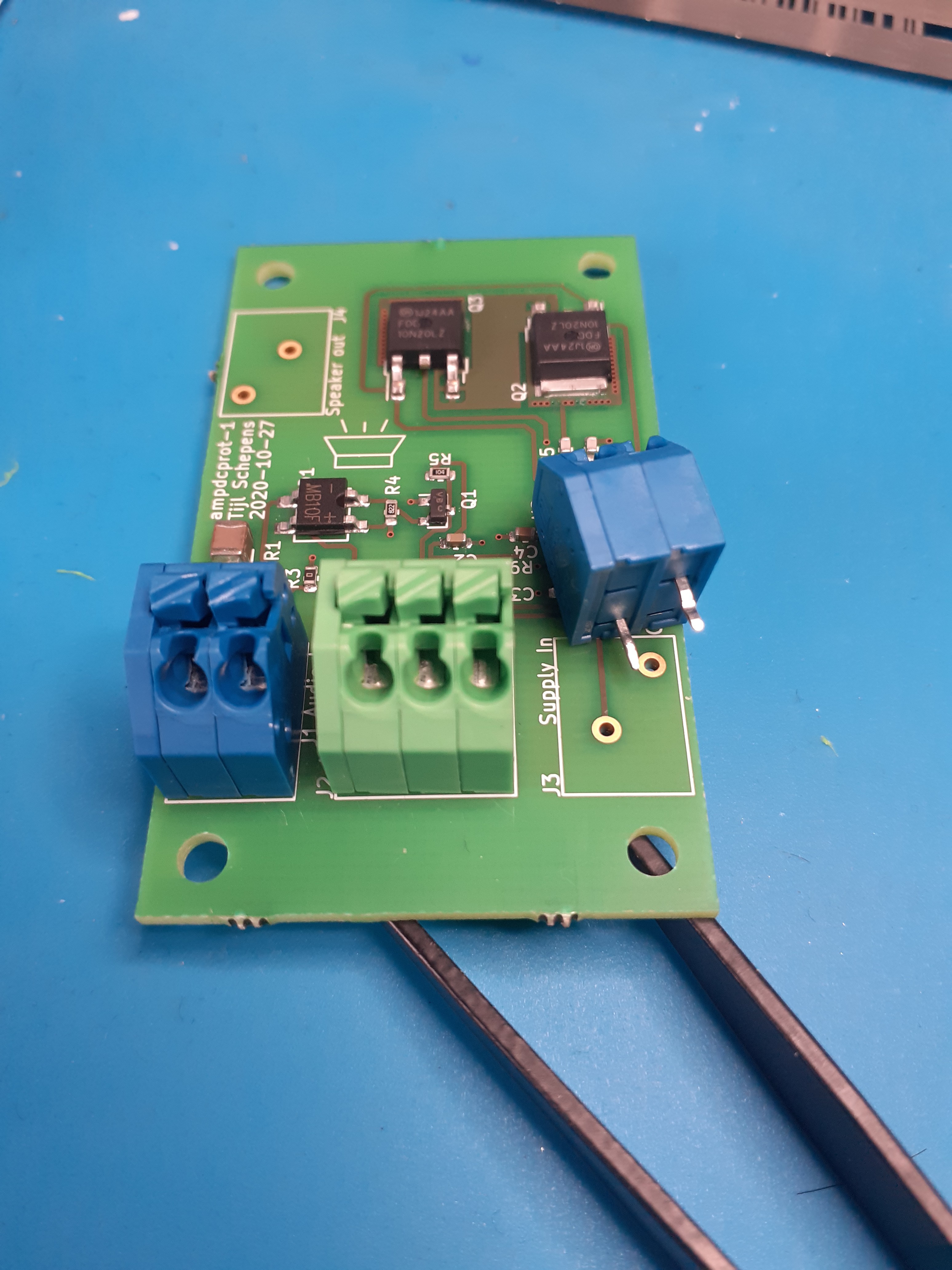 The pins of the connector are swapped. So they do not fit...
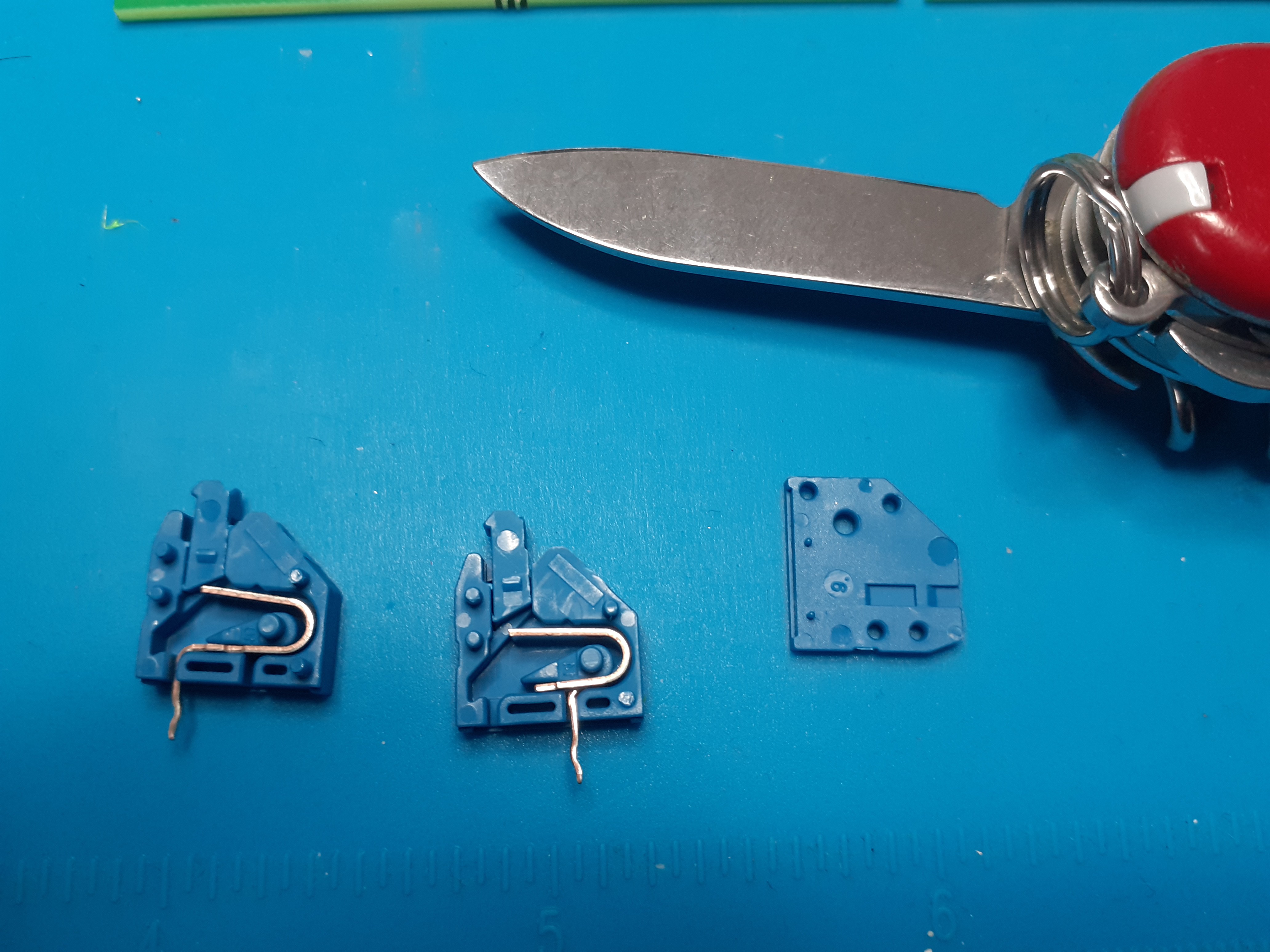 Now that the three parts of the connector are loose, we can just swap the pins. That way they fit into our connector footprint!

 mircemk
 Marco M
 256byteram