Close
0%
0%

The TransistorPixel

An addressable LED based on discrete transistors

timTim
Similar projects worth following
This is my intepretation of a daisy-chainable addressable LED based on resistor transistor logic (RTL). Each LED can be turned on and off via a single wire protocol that resembles that of the WS2812 (also known as "Neopixel"). Each device takes 17 transistors.

What does it do? A pulse longer than 500ns on the input will turn on the LED, a shorter pulse will turn it off. Pulses received after the first pulse will be forwarded to the next device. If no pulse is received for 20µs, the first device will be ready to receive pulses again.

Sounds complicated? In the end this allows to use a train of pulses to program the state of a number of LEDs connected in series. The same principle is used to control the WS2812 addressable RGB LEDs. The difference is that this circuit is implemented entirely using discrete transistor logic.

See it in action here

Longer design description: https://cpldcpu.wordpress.com/2021/02/27/the-transistorpixel/


PCB_PCB_V1.1_2021-08-30.json

EasyEDA PCB

JavaScript Object Notation (JSON) - 502.19 kB - 08/30/2021 at 07:17

Download

SCH_TransistorPixel_2021-08-30.json

EasyEDA schematics

JavaScript Object Notation (JSON) - 90.66 kB - 08/30/2021 at 07:17

Download

TransistorPixel_LTSpice.zip

LTSpice model Updated transitor model to PMBT3904

x-zip-compressed - 7.35 kB - 02/26/2021 at 15:24

Download

tpixel.mp4

Video showing three pixels in action

MPEG-4 Video - 8.25 MB - 02/26/2021 at 12:58

Download

  • Short description of implementation

    Tim02/23/2021 at 20:28 0 comments

    I am planning to provide a more detailed description of the design later. Just a quick summary for now. The design was simulated in LTspice, implemented in EasyEDA and manufactured at JLCPCB. It works nicely in real life, although I had to tweak timing a bit die to a slight mismatch in transistor models.

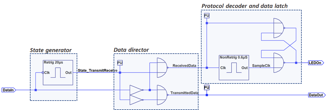
    The top level circuit is shown below. All blocks are implemented in resistor transistor logic (RTL). The purpose of the "stage generator" and "data director" is to control the flow of the input signal. It is either steered towards the decoder or towards the next device. The decoder will turn on the LED if a long signal is received and turn it off if a short signal is received. This is basically the same protocol that is used by the WS2812 with the exception that only a single bit of data is received by each LED instead of a full 24 bit RGB value.

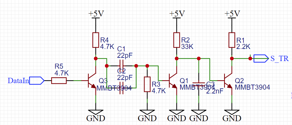
    The state generator consists of a retriggerable monoflop. It will essentially trigger after reception of the first pulse and cause the data director to forward any additional input signals to the next device instead of the protocol decoder.

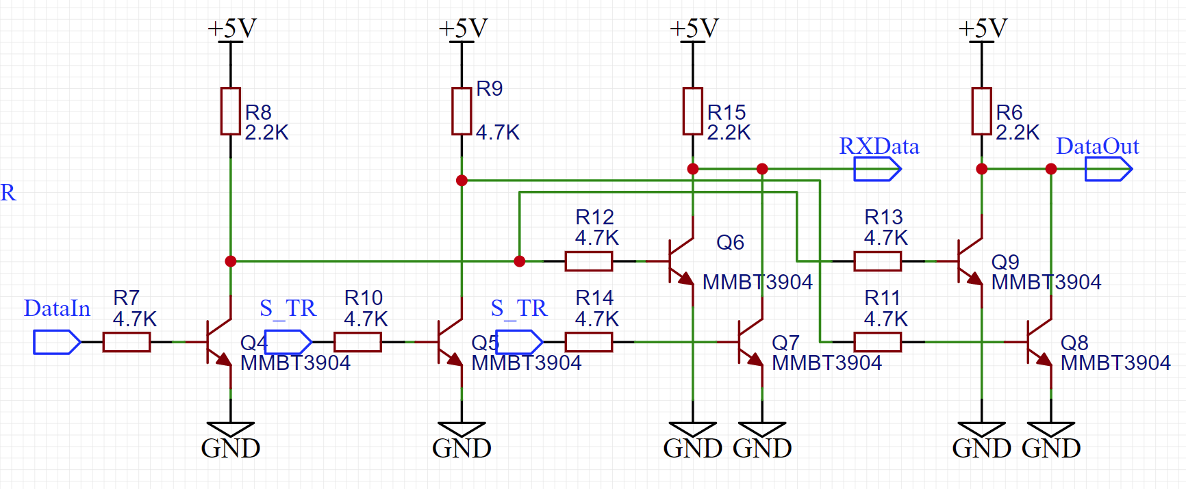
    The data director is a multiplexer that is implemented with two RTL NOR gates and two inverters. The circuit is straightforward and shown below.

    The circuit of the decoder and latch is shown below. The monoflop consists of the three transistors on the left. You can see the latch in the center and finally the LED+driver on the right side.

View project log

Enjoy this project?

Share

Discussions

iamkisly wrote 08/28/2021 at 21:03 point

Hi, Tim! Please share easyeda project.

  Are you sure? yes | no

Tim wrote 08/30/2021 at 07:18 point

Done, see files.

  Are you sure? yes | no

Mike Szczys wrote 03/03/2021 at 15:48 point

Great implementation, cheers to esoteric timing protocols! :-D

  Are you sure? yes | no

Justin Davis wrote 02/26/2021 at 15:17 point

In the simulation files, it looks like the forwarded pulses get slightly shorter after each stage.  After the 6th stage, it looks like the voltage drops off and the pulses are no longer forwarded to the next modules.

  Are you sure? yes | no

Tim wrote 02/26/2021 at 15:26 point

Good observation. The archive still had a transistor model for a chinese MMBT3904 clone. I updated it now to the PMBT3904 which performens better.

The issue is a difference in storage time.

  Are you sure? yes | no

Yann Guidon / YGDES wrote 02/26/2021 at 12:25 point

To get greyscale, you can string them and get luminosity by clumping groups together :D

  Are you sure? yes | no

Tim wrote 02/26/2021 at 13:02 point

You could just use the protocol to control them by PWM. You get half a million updates per second.

  Are you sure? yes | no

Yann Guidon / YGDES wrote 02/26/2021 at 13:42 point

not false. Though good luck with that.

  Are you sure? yes | no

Yann Guidon / YGDES wrote 02/26/2021 at 12:24 point

https://hackaday.com/2021/02/26/diy-all-transistor-addressable-pixel

  Are you sure? yes | no

Similar Projects

Does this project spark your interest?

Become a member to follow this project and never miss any updates