-
1Selection buttons and Alarm
![]()
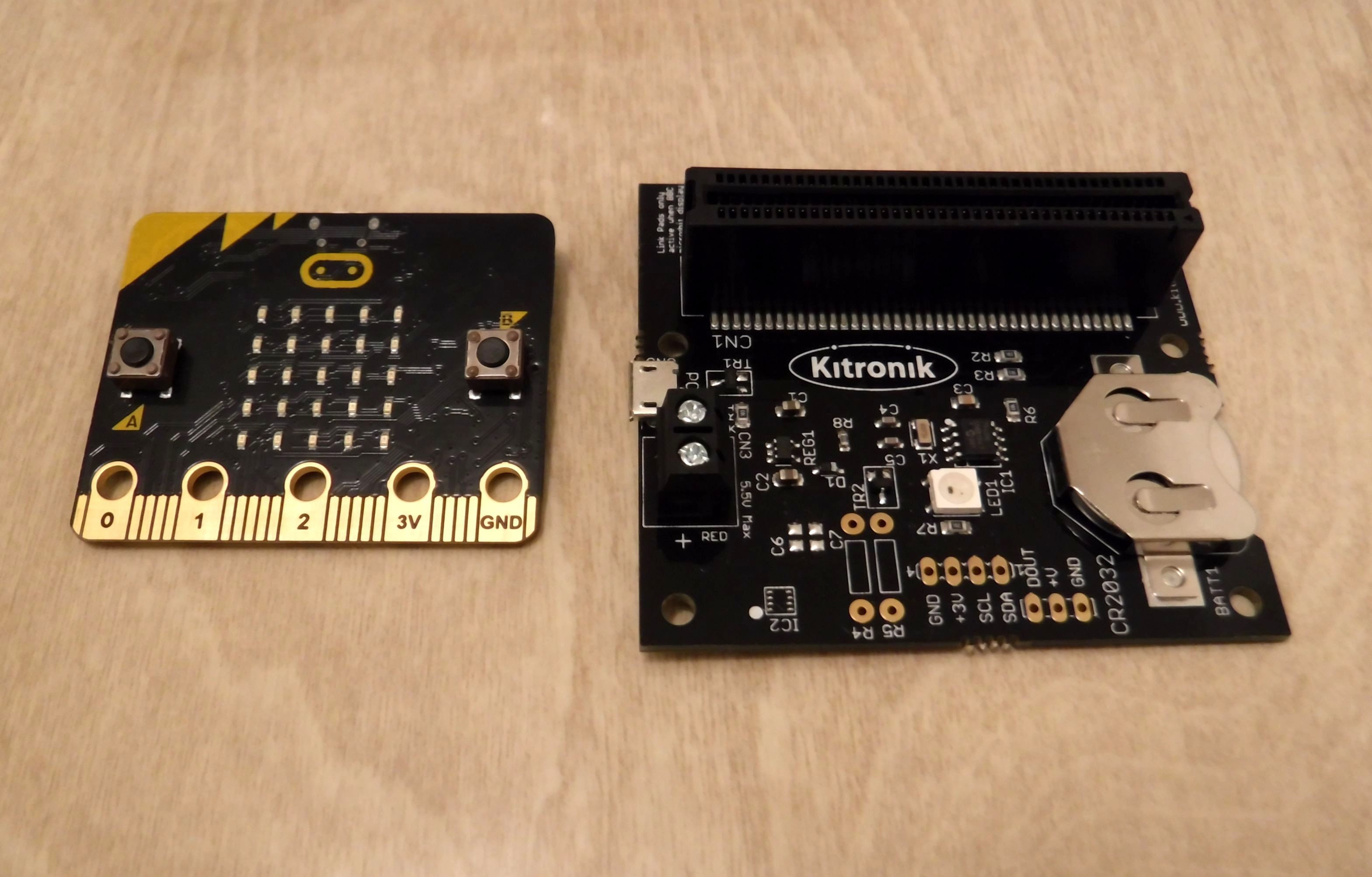
The Microbit will fit into the socket in two orientations, facing the main part of the RTC of facing away.
If facing the main part of the RTC the link connections cannot be used however, if the Microbit is facing away from the main part of the board then we can make use of these connections.
The assembly starts by soldering a right angle SIL pin header onto the RTC, this is to enable the connections to be made with push fit connectors.
The RTC is fitted by 4 * M3 (10+6mm), M/F standoffs with M3 nuts which are secured to the lid with 4 * M3 (8mm), screws in the prefabricated holes.
The switches are fitted in the prefabricated holes in the lid.
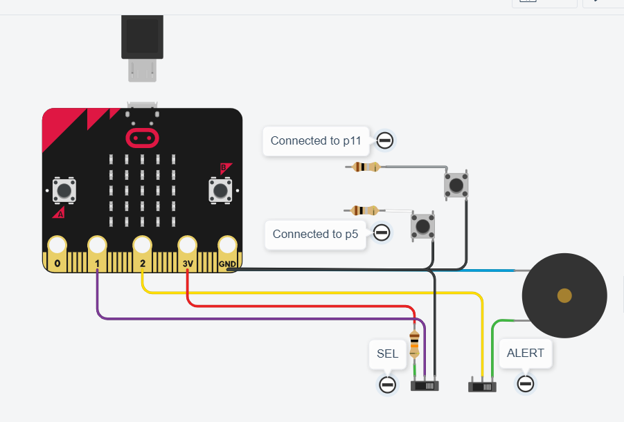
The connections required are:
GND, 3V, P1 (set), P2 (alert), P5 (sel) & P11 (inc)
Note *** Resistors (1R), on the diagram for P5 & P11 are simply reference connection points as direct connection to these pins on the Microbit in Code blocks is not available at this time. ***
P5 is the external connection for Button A which is connected by a SPST momentary switch. One connection to P5 and the other pin is connected to GND this button is for column selection during time setting.
P11 is the external connection for Button B which is connected by a SPST momentary switch. One connection to P11 and the other pin is connected to GND his button is for number increment during time setting.
P1 is a SPDT (on-on) switch which is used to enable or disable the setting options. The centre pin goes to P1 whilst one pin to connected to GND and the other to 3V via a 10k resistor. This enables a H (3V) and L (0V) to be applied to this pin. When P1 is connected to 3V this enables the time setting options and when 0V disables time setting. Thereby controlling whether the A & B buttons have any effect.
P2 is a SPDT (on-off-on) switch which is used to enable or disable the alert sounder and optional external lights.
The alert sounder is a Piezo Buzzer (simply affixed with a double sides sticky pad), requiring a pulse drive which is provided by the Microbit.
-
2The main components
![]()
Plug the Microbit into the RTC and power the RTC board via USB or the screw terminals.
The Tick LED will start to flash and shortly after this the time will be displayed.
If this is the first time of use the displayed time is very likely to be wrong and will need to be set to the correct time.
Mode selection.
Pressing the Selection (A) & Increment (B) buttons together will allow cycling of the Mode options between Time & Alarm.
Setting the Time
The time setting is in 24H mode.
Use the Selection button (A), to move the LED across the top row, this indicates the column where the time can be changed. The selection columns correspond to H, H, M & M.
Where H = Hours and M = Minutes.
Having selected a column press the Increment button (b), repeatedly to increment the count by one on each press. The counts are indicated in binary, after all its a Binary Clock.
The increment button only increases the count and once the maximum is reached resets to zero, further presses will again increase the count.
Once the first column time is set, press the Selection button for the next column then use the Increment button to set the column time.
Note: *** When you set the Time or Alarm you will need to enter a time in the selected column even if the time in the column is to remain unchanged as skipping a column sets that column time to zero ****
Repeat the process until the time has been set using all 4 columns.
Press the Selection button for the fifth time to move it to the fifth column and the time is set.
Setting the Alarm
Setting the Alarm time is done in exactly the same way as for the Time.
In order for the Alarm to be triggered on the required time leave the Mode set to Alarm.
To switch the Alarm off set the Mode to Time.
To display the Alarm time set, cycle the Mode between Time and Alarm and the Alarm time will be displayed for a short period of time before reverting to displaying the current time.
The Alarm time is not stored in the RTC, therefore if power is removed it will require resetting.
-
3Box
![]()
![]()
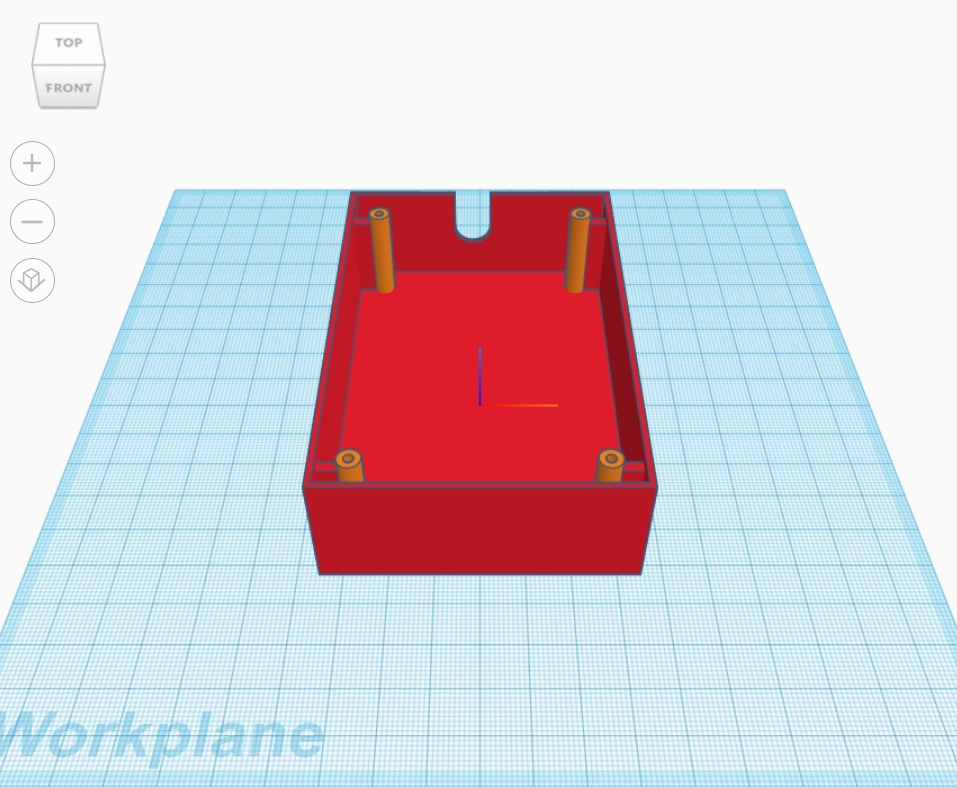
The project will sit at the appropriate angle to view the clock but a box adds a sense of permanence.
You could buy a suitably sized box and cut and drill out the appropriate areas to allow the Microbit to fit in the socket.
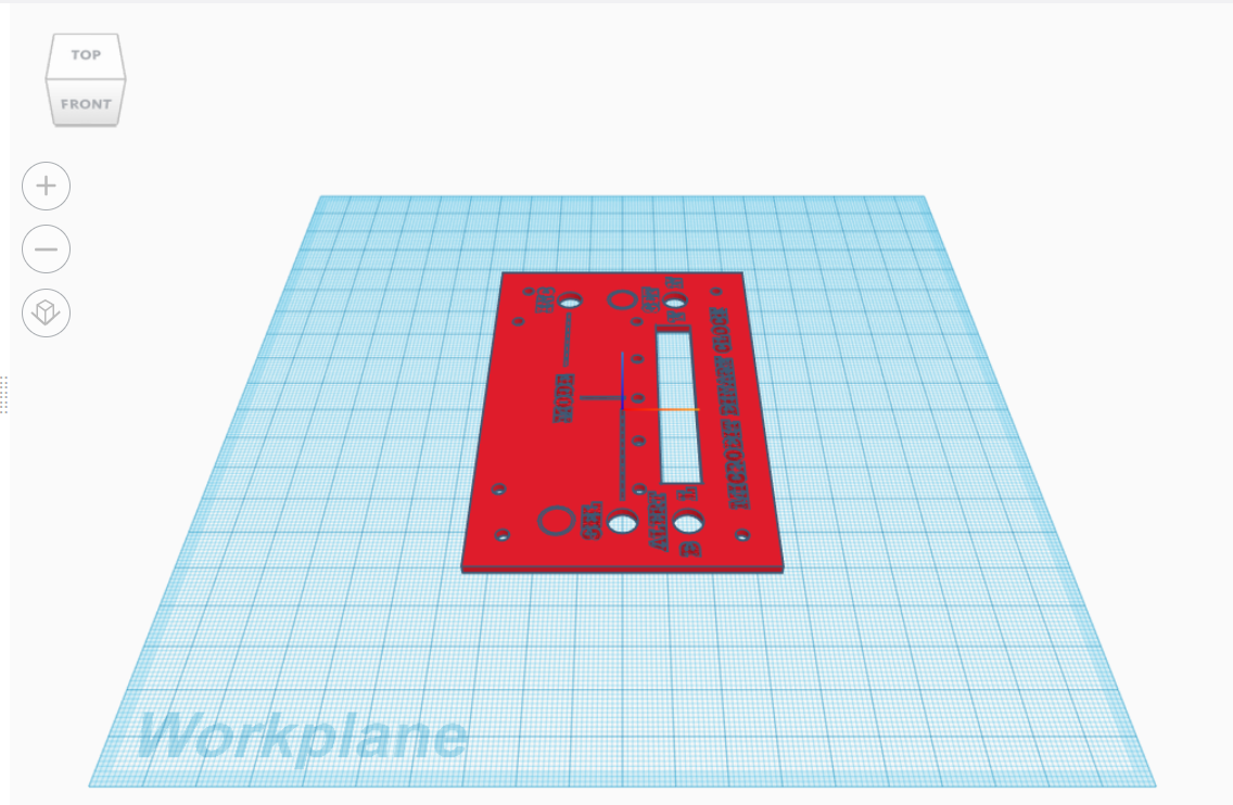
However; additionally I wanted to duplicate the Microbit buttons along with other controls and indicators.
Typically, legends will need to be applied to the box to identify buttons.
These could be applied by hand; painted, engraved or applying labels.
A method to realise all these options would be to 3D print the box but first we would need to create a CAD file with which to create the printer file.
The file creation options are hand drawn or drawn with code.
I opted for "drawn with code" using Tinkercad CodeBlocks
The files for the Box Lid and the Box Base can be found on Tinkercad CodeBlocks
Micro Binary Clock
Using a Microbit and an RTC to create an Binary Clock with 2 display options.
Discussions
Become a Hackaday.io Member
Create an account to leave a comment. Already have an account? Log In.