What exactly JPC does?
Basically, the JPC duty is to turn ON and OFF five relays one after another to control the pneumatic actuator solenoids.
- Arduino NANO:
As the main controller unit, JPC uses an Arduino NANO. this shows the main reason for using the JPC, reducing the costs. A jet pulse controller electric panel designed using industrial relays and timers can cost up to 200$, but by using this board, you can reduce the price to about 30$.
- Relays:
On the JPC, you can see five Omron G2R relay, these relay contacts will be connected to the pneumatic actuator solenoids. whenever a relay gets activated, one of those solenoids will get activated as well, when that happens, the bag filter in the dust collector will get punched with compressed air, and so the collected dust in it will get stored in the actual dust storage.
- Seven-Segment Display:
As you can see in the pictures, there's a seven-segment module on top of the LM2596 module. this display will show you the ON-DELAY and the OFF-DELAY time. the two left segments show the on-delay in deciseconds, and the two right segments show the off-delay time in seconds.
- The Electric panel:
As you may already be noticed, this is an industrial-grade project, so it needs an electrical panel to be installed in industrial situations. this is the panel that I made for it:
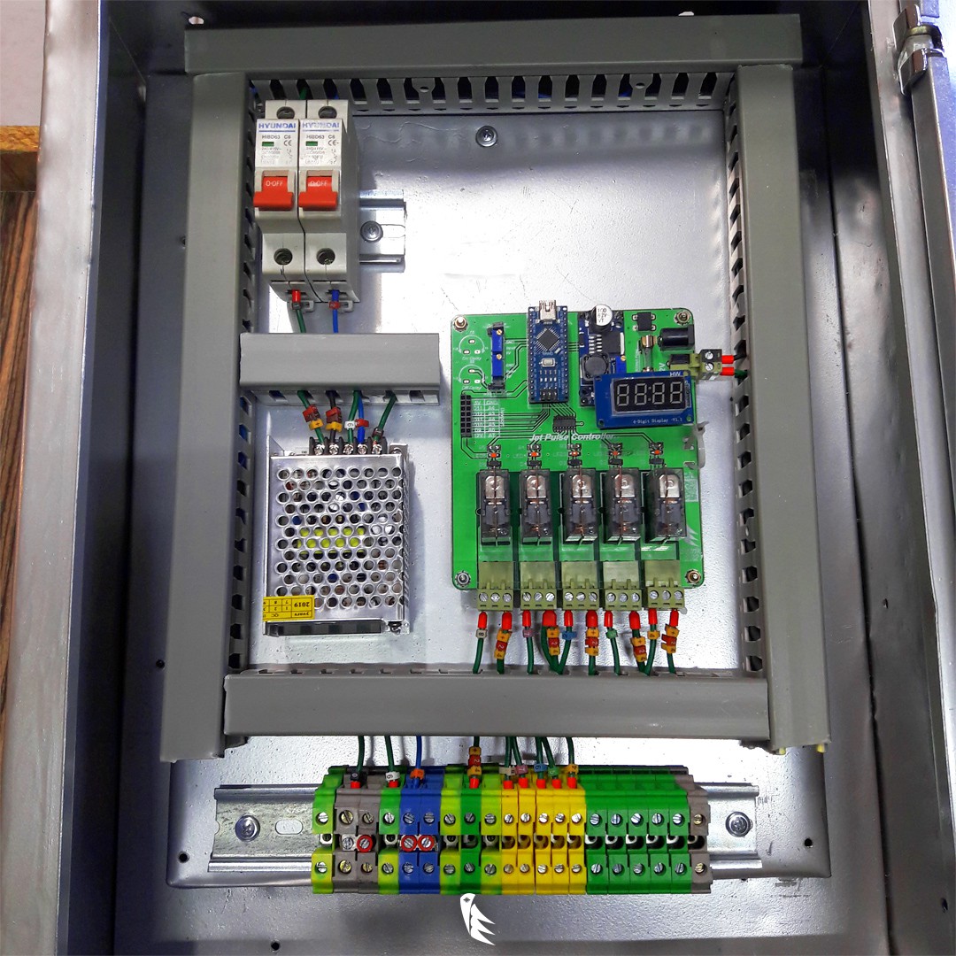
On the terminals (the colorful things on the bottom), you should connect a 230V-AC for the main power, which is the Gray (phase) and the Blue (Null) terminals. then to the Green terminal, you should connect a +24V-DC (depends on your solenoids voltage), the negative 24V should be connected to the negative pole of the solenoids. the other pole of the solenoids should connect to the yellow terminals, which are the output +24-DC.
- Power Supply:
The voltage of the JPC board is 12V, you need a 1A-12V power supply to turn on the board. but you can easily turn it on with 24V, with some slight modifications.
These modes are changing the relays to 24V relays, change the LEDs current limiting resistors if you like, and make sure that the LM2596 module output is exactly 5V.
- devPORT:
For future upgrades, you have a development port on the board. this devPORT is a 2*7 female pin header that gives you: 5 GPIO pins, 6 ADC channels, 5V, 12V, and GND.
 setCREATE

 Andy Smith
 IoT-devices, LLC
 Timothy Woo
 shashikanth
Nice panel, I really dig industrial controls. SO if I'm following, this just controls the flow of air to nozzle on the inside of the dust filter, and the blasts of air knock caked-up dust off the filter pleats?