techknight
-
Deciphering Viewports
05/01/2021 at 00:59 • 0 commentsAs we discussed in the previous installment, we can switch resolutions and send color palettes via the CMD01 being sent to framebuffer control.
Now, as we discussed there must be a way to be able to change where the on-screen viewport points to in memory.
When discovering the command, I found this in ROM:
![]()
To most people, this doesnt mean much. But... This is called on startup very early in the process as that 8051 ROM boots. the location in RAM 0x710 is the same areas where CMD01 configures for its viewports.
With that known, the above basically gives us an initial state the framebuffer is during startup. So with my analysis of CMD01 in the previous installment, lets take a peek at ROM to figure out the code flow and see how the viewports are configured.
Looking at the startup code, its looped 3 times. So thats something to keep in mind for going forward.
One thing that clued me in however, was from a conversation we had with Michael Searce. He had mentioned the WS4000 had at least 3 framebuffers that can be shown on screen at any point in time. Aha. So.... lets follow the code-flow to confirm our suspicions.
![]()
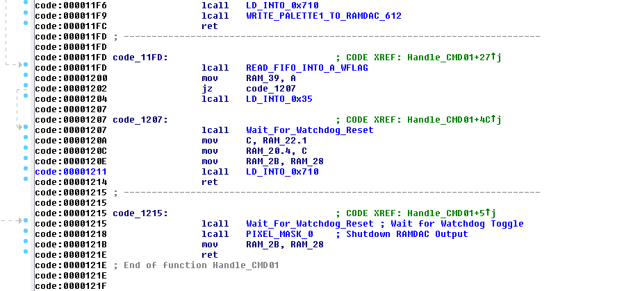
If we thumb through the CMD 01 handler, we can see towards the bottom here our familiar memory location 0x710 that I have labeled. So, lets take a look at that subroutine.
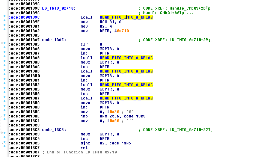
![]()
So if we follow this code, First off it reads a byte from the FIFO and stores it into Register 2. Then it sets the DPTR to point to 0x710 in RAM. It then reads 4 bytes from the FIFO, then performs a calculation whether it sets the 5th byte 0x30 or 0x60, but it is not read from the FIFO so it does not matter here.
Then.... you encounter the djnz instruction. This Decrements R2, and if its not Zero, it will jump off back to $0x13A5 which reads another block of 4 bytes.
So given this, it certainly confirms the information Mike has supplied about having multiple framebuffers. Trouble is, there are no boundary checks so technically you could copy 4 byte blocks 255 times. That.... would be bad because you will corrupt the rest of SRAM, and then run out of it! So.... don't do that.
So.... if we reference what we see in the above code, versus the example byte values in the Startup code, we can make a reasonable assumption of what to send it.
We can now formulate an example command:
01 02 03 00 00 01 00 00 00 F0
So lets break this down a bit:
01 = Command 01
02 = Enable Graphics Output
03 = Resolution (768x480)
00 = Send Palette
00 = Send Animation
01 = Number of 4 byte viewport blocks
00 = Viewport Byte 1
00 = Viewport Byte 2
00 = Viewport Byte 3
F0 = Viewport Byte 4
So this is what we know so far. Not much at this point, I know. But at least we have something to start with. And matter of fact, This is the command I used initially to get graphics to show up on the output at all as this was critical.
So at this point its a process of elimination. Try changing byte values and see what the hell happens. But before we do that, lets take a look at the value F0 at the end
This was the value that was in in ROM to begin with as an initial setting, so there must be some significance to this. So lets take an educated guess on what that means. So the first thing we should to is convert the 0xF0 to Decimal, which is: 240. Huh interesting. My mind is trained to see patterns so knowing the framebuffer height is 480, its awful convenient that this value is 240.
So, I must assume 0xF0 is the Viewport height Divided by 2. so if we multiply the decimal equivalent of 0xF0, we get 480. Magic....
So that just leaves 3 values that are unknown at this point. Sending this command as it is will use the default SMPTE Palette that is built into ROM, and show a 768x480 image of whatever is sitting framebuffer.
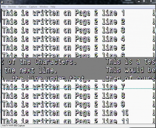
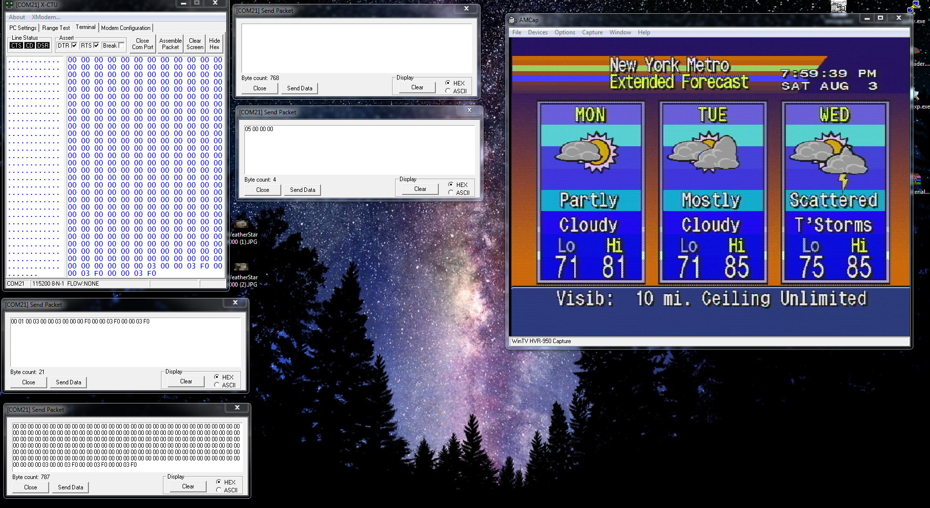
So the next step in this process is lets get something drawn into the framebuffer. We start with something like this:
![]()
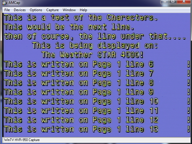
So what we did here was simply draw some text on the screen. This will give me a reference where I am at in the framebuffer before I get lost.
To understand this: Page 1 means the first 480 lines of framebuffer memory. Line 481 would be "Page 2". this will help me identify where I am at in RAM. and of course the Line numbers are self explanatory. Each line is 36 pixels tall so i can easily to the math.
So.... Lets change the first byte value and see what happens:
![]()
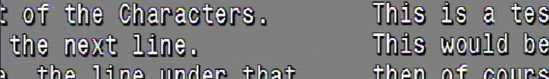
Woah! it appears modifying the byte jumps the position of the text over, and it kinda "Wraps around" Ok.... what does that mean? I gotta sit and think about it for a bit.
I don't have any footage of my experimentation to know what value jumps it by how much. What I have figured out, is the first TWO byte are little-endian formatted "offset" at which pixel will be the start pixel that the 1st line begins on, for the output display.
The other thing is per increment of 1 of the value, the screen shifts over by exactly 8 pixels. So this means that the 16-bit word for the offset pointer, is also X8.
now that clears up what the first 2 bytes do in that 4 byte command. we know what the 4th byte is.
That just leaves the 3rd byte. What i quickly learned is the first 4 bits (nibble) of that 3rd byte change how the framebuffer is being displayed as far as chroma key. Turning a bit on would enable the video passthrough. turning that bit off would disable the video passthrough on graphics. Basically, disables the chromakey/alpha. not particularly important, but good to know.
So we are left with the upper nibble. We have 4 bits on the upper nibble which gives us 16 potential states to chose from. However, what ive noticed is each bit acts independently of one another.
So therefore, 0, 4, 8, C are the only values that do anything. Any value in-between wont register. So its looking at the bits individually.
So lets pass something random in there and see what happens:
![]()
Throws me way down in memory! So i am not quite sure at this point what to make of it. we know the offset value can only be a maximum of 0xFFFF so this might be what bumps it up to the next block. However for now, lets not think about that for a second, and go back to the 2 first values that we do know. See how far we can push it.
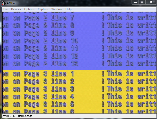
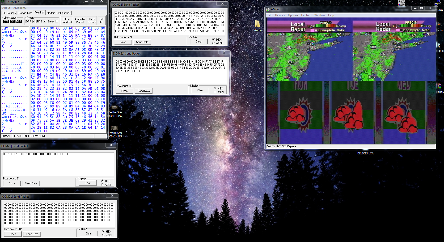
So lets push those 2 bytes up to the offset for line 481 and see what we get: (We will get to the math later)
![]()
Well.... we have a problem here. We can see that we now start to show what is at line 481. and it continues. But then you see somewhere in the middle there it just completely ends. And when it does end, it seems to show whats back at the very beginning of the memory block its currently looking at. and its totally out of alignment.
Almost looks like an overflow problem, doesn't it? Well lets take a look:
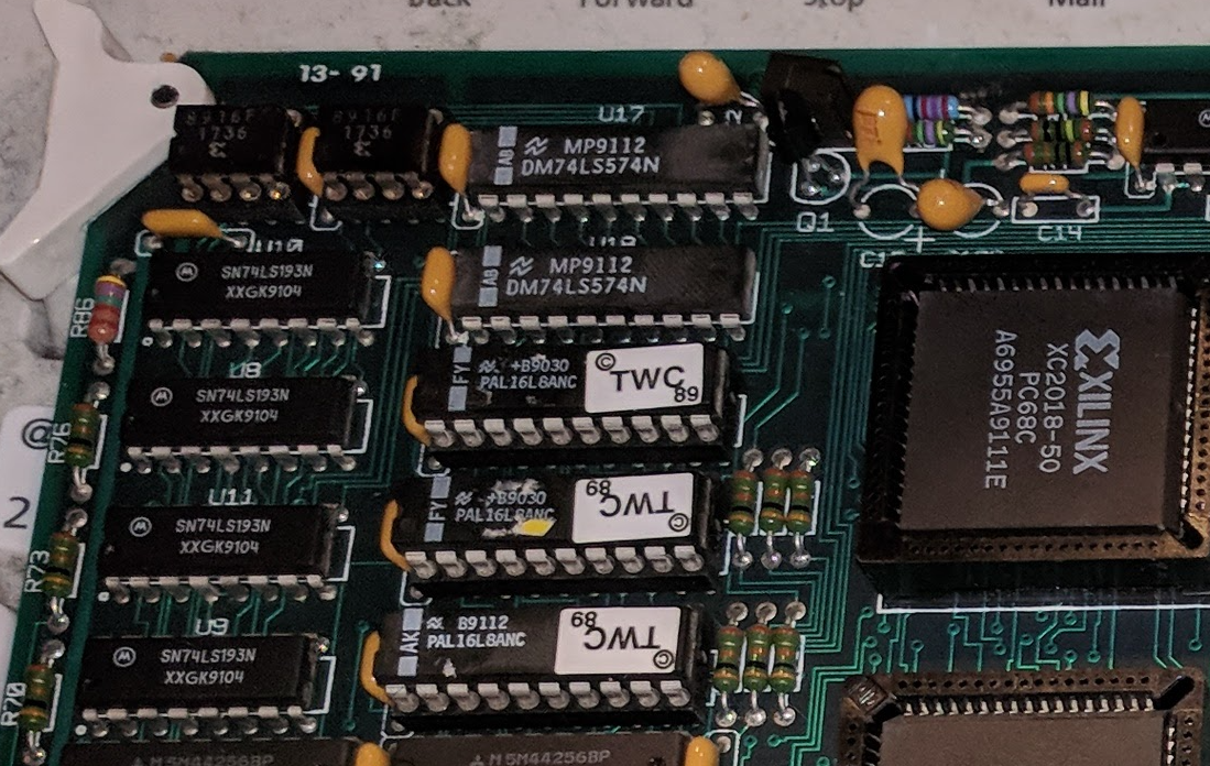
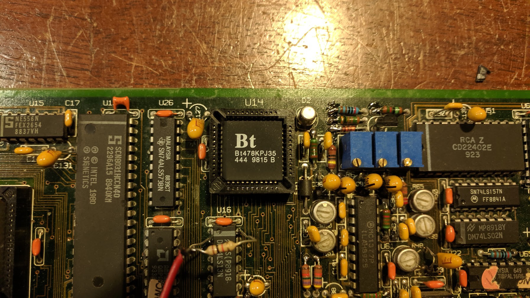
![]()
This is a picture clipping of the upper left corner of the graphics card. To the left, you can see a set of 74LS193 ICs. these are 4 bit counters. There are 4 of them... Stands to reason we can make a pretty good assumption that these counters are responsible for what pixels are displayed on the screen, and where... given they are coupled to the PALs, like so:
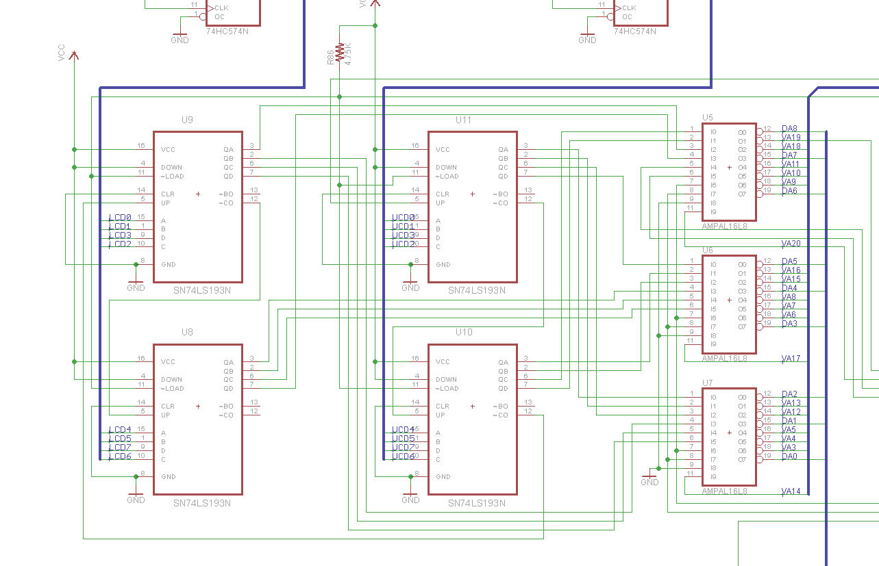
![]()
Notice these chips can count up, down, can be loaded with a value, etc...
With this information, lets do some calculations. We know that each 1 tick of the count value will represent 8 pixels on screen. So. a count value of 65535 or the maximum value of a 16-bit word, represents 8191.875 blocks of 8 pixels. so if we multiply that to get per pixel, thats 524,280 total reachable pixels with that 16-bit value. There are 768 pixels per line.
So... That gives us a window of 682.65625 lines before the counter overflows! And on that screenshot above, That's about where we end up before it "wraps around".
Knowing this, That suddenly triggers the memory of that 3rd byte. That must be the "paging" register for each group of 682 lines.
However there is a caveat. Notice its 682.65625 lines. Well... that means at line 682, somewhere at .65XXX we lose pixel information.
Therefore line 682 is basically lost. And since we need to switch pages using the paging register to see line 683 and higher, We absolutelly cannot draw anything that crosses these "overflow boundaries". So effectively, line 682 is useless. you have to skip over from line 681 to 683 and use 2 viewports on screen at the same time with two different window heights as we discussed above.
This is a pain in the ass, and one of the limitations of the framebuffer. So personally, I skip over this. Anything past line 480 is basically wasted except radar. radar takes 120 full lines, so you can fit it within a 682 line "page"
So with the paging register, we have 4 682 line pages essentially. and you cant display between pages that cross the overflow boundary without two viewports.
With the above information, we can now clarify the 4 byte viewport values:
00 = Pixel Offset Low
00 = Pixel Offset High
00 = Page and Chroma key
F0 = Viewport Window Height / 2
Hey we are getting somewhere.... On to the next one.
-
Resolutions
04/30/2021 at 01:40 • 0 commentsNow that we are able to draw images into the framebuffer, we basically have the graphics card under our belt now. Except for one thing....
Framebuffer control. We briefly touched on this in a previous blog entry, but now its time to go into some more detail.
Thing is, we can draw images into the framebuffer that is being displayed, but unfortunately drawing is fairly slow. so you would see the drawing process on screen.
So, to prevent this from happening and to provide a better experience to the viewer, we need to double buffer the drawing. The way to do this is simply drawing graphics/text into other areas of RAM that are not currently visible on the screen.
This is going to require more experimentation and studying of one of the most important commands. CMD01.
This command not only contains the Palette data thats sent, it also contains up to 3 framebuffer window settings. So, you can have up to 3 different set viewport partitions on screen at the same time. Plus there is CMD06 which is an overlay window that comes up from the bottom on a specified height.
from Studying the ROM, this was my initial analysis on the CMD01:
===============================================================================================================================================
Command $01: (Ex: 01 00 FF 00 00 01 00 00 00 00 )
Byte 1 gets copied into a couple other registers before manipulated and written into the FPGA.
Byte 1.0 = Enable/Disable Local Video
Byte 1.1 = Does a multiply by 2 on the counters. (Maybe switch active pages)
Byte 1.2 = Disable/Enable Graphics Output. When disabled, Ends CMD01 processing entirely. (Set to Disable, MUST be last byte when Set!)
Byte 1.3 = Does the same thing as Byte 1.1 (MAybe at different times though)
--
Byte 2 (Switches Output Resolution)
0 = 384x120
1 = 384x240
2 = 768x240
3 = 768x480
Byte 2.0 = Sets/Clears $22.1
Byte 2.1 = Sets/Clears $20.6, and $28.3
-------------------------------------------------------------------------------------
Byte 3
Condition Flag whether to do a full Palette Copy and Counters signaling copy.
If 0 We skip Palette load, and Read Byte 4.

Byte 4 if Byte 3 = 0
Condition flag whether we copy animate data or not.
If 0, we skip animation info and go into copy data into 0x710. Return from cMD01.
-------------------------------------------------------------------------------------
-------------------------------------------------------------------------------------
Byte 3
If 1 then we load the palette1 with data. A full 0x0300 byte load is EXPECTED/REQUIRED!

Byte 4 if Byte 3 was 1.
Still serves the same purpose, with an addition.
IF 0, We skip the animation info and go into the copy data into 0x710. BUT, Now, after that, the recently loaded Palette gets copied into RAMDAC. End CMD08
-------------------------------------------------------------------------------------
If Byte 4 > 0 in either case, it loads the appropriate info for Palette animation.
Byte 4 = Number of Blocks of color palette to animate. Each Block is 7 Colors.
Each byte after this is each block location. Last byte is the speed at which the animation occurs.

================================================================================================================================================
Sorry if the above is confusing, but it was my quick analysis at the time. But it will get a bit more clear the further we go on.
Now, if we put 768x480 images in framebuffer, we only have enough RAM for maybe 4 of those images. We already know from watching in the past that the radar is at least 6 frames of animation. These frames are obviously not drawn in real-time because it would be too slow. So its definitely pre-rendered into RAM, and the pointers move around to point where each image has been drawn in VRAM.
So in order to do this, the machine has to switch resolutions to a lower resolution so we can "fit more" into memory.
Thus enters Byte 2. This byte seems to change the resolution of the output.
The way the lower resolutions work, is it takes the full 768 pixel line and splits it into two halves. so the second group of 384 pixels (on the right side) show up 1 line below the first set. So basically like Even/Odd lines.
As pictured here:
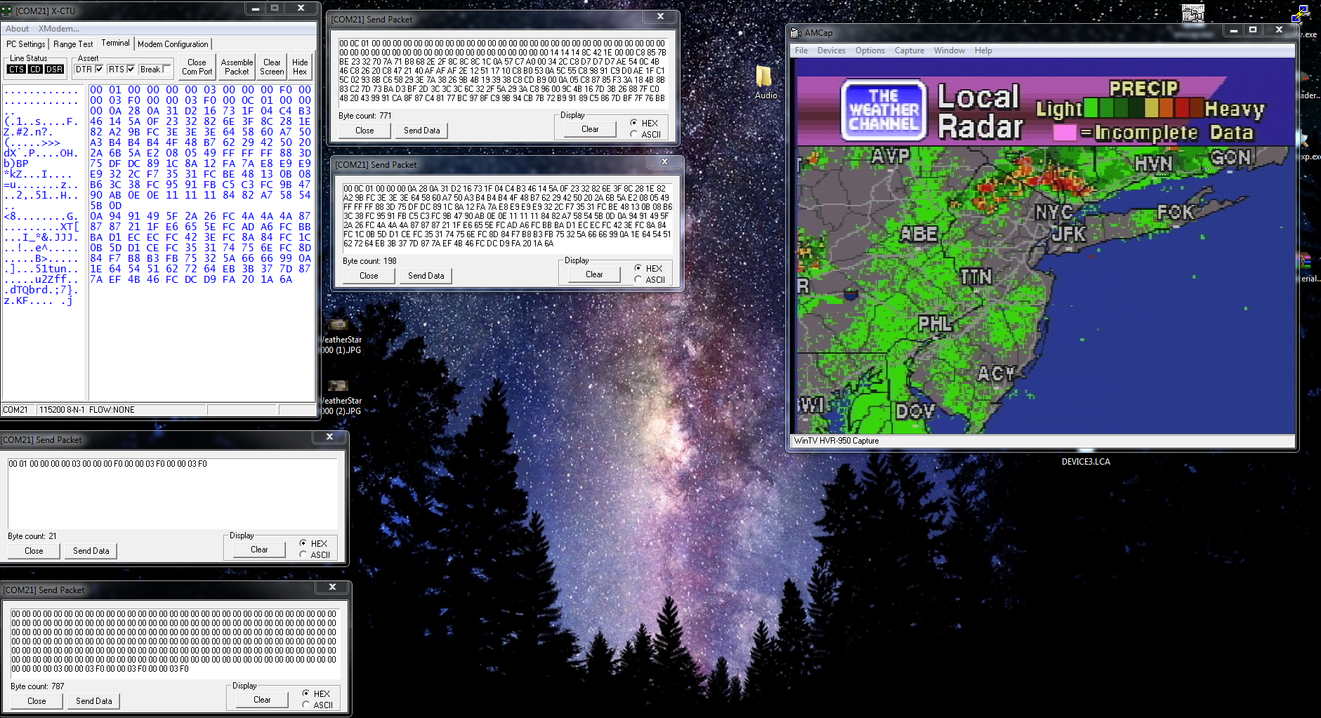
![]()
I sent the radar image and switched the Palette to the Radar color palette.
You quickly notice that the image appears to be split in two. This is the odd/even line that I was talking about. the 2nd line of the image is drawn to the immediate right of the 1st line. This essentially allows you to double your framebuffer space or even 4x your framebuffer space for lower resolutions.
This is how radar was accomplished.
So. Modifying byte 2 to set the framebuffer to 384x240, yields this:
![]()
Perfect. that image looks normal. And its occupying only 384x240 in framebuffer, but.... its technically 120 lines of 768 pixels as i explained earlier.
Confused yet? Good! :-)
In the next part, we will talk about the framebuffer pointers and how we achieve which section of memory is show on screen.
-
Degredation
04/28/2021 at 23:25 • 0 commentsSo as we saw in the previous blog, we have an image being drawn in the framebuffer, and the colors set.
The problem though, I noticed that some of the colors either not being set, or kept flipping to different colors after they were set. I started doubting my framebuffer command that I was sending, or my setup and started to get frustrated.
But then it suddenly dawned on me. Maybe this was the degradation that started happening to alot of these machines later in their lives. This was acting very similarly.
Here are some well-known cases of it going on in the field:
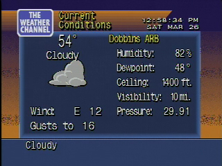
Here is a picture of one in my files that also had problems:
![]()
Here is another one a friend of mine owns which is running my software:
So my mind quickly shifted from being a problem on my end with my experiments, to the potential of hardware failure.
Now giving my troubleshooting skills are very sharp, and I have repaired electronics for years and years prior to this point, I had a pretty good idea right where to go to.
the RAMDAC. So, on an indexed-color system, most graphics cards from this era have whats called a RAMDAC. the RAMDAC means Random Access Memory Digital to Analog Converter.
Without forcing you all to go to wikipedia, the nutshell is basically this. the RAM of RAMDAC means there is a small section of SRAM inside the chip which holds the R, G, B values for each color index starting from 0, up to 255. DAC is the analog converter. it takes the digital R,G,B values that are stored in the SRAM lookup table, and then applies those as a voltage or current. the higher the number for each R,G,B value, the higher the voltage/current level is on the output. and 0 being no output. Each value from 0 to 255 is applied from the bus through an 8-bit port. This is known as the index. this index will pick which slot to apply to the DAC output with that slot's programmed color values. There are also mask registers, etc but i don't want to get into that, and the 4000 doesn't use them anyway.
Pretty straight forward.
With the colors suddenly and spontaneously changing from their set values, or unable to be changed, points me to believe the SRAM inside the RAMDAC has failed in some rather unique way. So it is unable to retain its set RGB values. so bits will flip. when bits flip states, its going to change the color for that index value.
So the next step at this point is to just basically replace the BT471.
However there is a catch. the BT471 is hard to find since it wasnt commonly used. Everyone used the BT478, as it supports full 8bit RGB.
So, i bought a few of the BT478s on ebay. I figured why not, plus it can upgrade the possible number of colors to its mask! or so i thought.
I put the new chip in, but the picture was very dark. I even sent full RGB888 values, and the picture was still very dark.
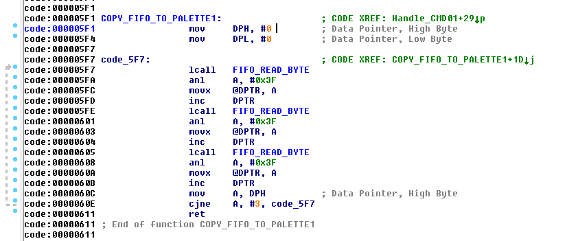
So i took a peek at the ROM, and sure enough this little bit here stands in the way:
![]()
If you look at that, you can see the anl 0x3F opcode. That basically clips off the byte value and keep it as 6 bits. So damn.... So much for full 8bit RGB. haha. Those operations are peppered everywhere in ROm so its not as simple as just patching that bit out.
So i left it be. I figured i was going to need to replace the BT471 with another 471.
Turns out, studying the datasheet there is a pin which you can connect to ground, and it forces the chip to run in backwards-compatible RGB666 mode!
So, lets do that!
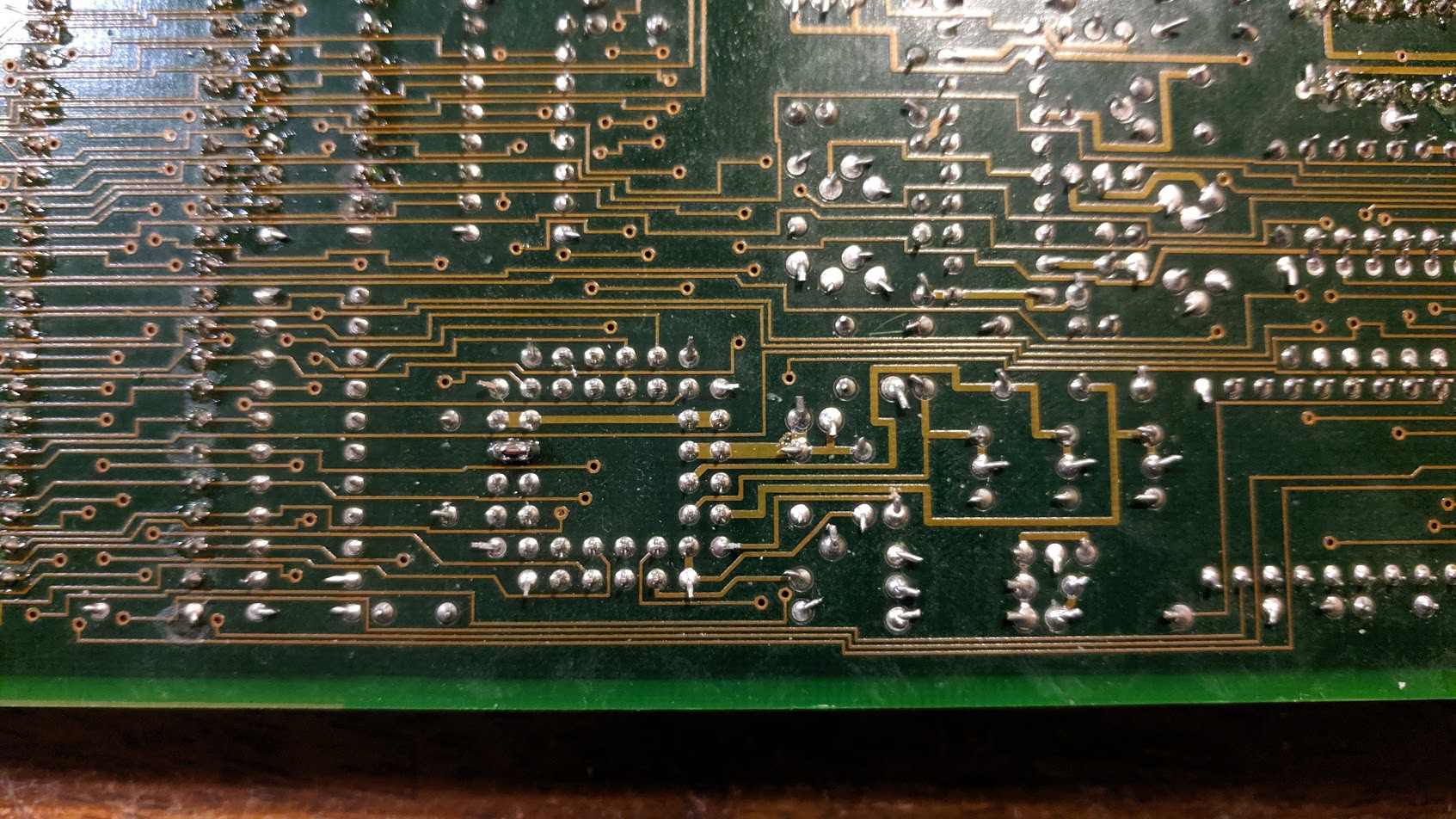
![]()
Here is the new chip installed.
![]()
Turns out, the pin I needed to ground was right next to a ground. So i didnt even need a bodge wire. the pin was unconnected on the original design as well, so all I did was lay down a solder blob to ground the pin.
Time to see if it worked:
![]()
BOOM fixed! that's exactly what it was. Although there is still some color noise, but that was due to the graphics card itself rather than the RAMDAC.
So that was exactly the cause. the SRAM cells start failing in the BT471 chips over time. So any degraded unit you saw back in the day, this was the cause.
Perfect. Now we can move on....
-
Getting an image on screen
04/28/2021 at 22:52 • 0 commentsIts been awhile since the last post because I caught COVID-19 at the beginning of april and its been a fight for my life. Even included a trip to the ER at one point. Finally things are starting to subside outside of a lagging cough. So hopefully things get better from here. Nasty stuff. But I digress...
Now that we have some form of framebuffer knowledge such as drawing text on the screen and other little bits and pieces, we need to see what else we can do.
At this point, lets see if we can get some graphics on this thing!
In the very beginning, i just simply took static images generated by the WS4000 Simulator over at Taiganet, and then converted it into a RAW indexed-color bitmap to be displayed on the screen.
The other part to this is the color palette table. Since the image is indexed color, it will have its own palette assigned to this. all GIFs work like this. and in some cases, each "frame" in an AGIF will have its own palette.
So this makes it easy to bring over to the 4000 framebuffer to see how it looks.
I wrote this little routine here:
Sub LoadStandardImage(Filename As String, RGB666 As Boolean, StandardImagePalette() As String)
	'Load Standard Memory
	Dim img As Image = fx.LoadImage(File.DirAssets, Filename)
	Dim buffer() As Byte = GetPixels(img)
	Dim width As Int = img.Width
	Dim height As Int = img.Height
	For x = 0 To width - 1
		For y = 0 To height - 1
			Dim i As Int = y * width * 4 + x * 4
			Dim b As Int = Bit.And(0xFF, buffer(i))
			Dim g As Int = Bit.And(0xFF, buffer(i + 1))
			Dim r As Int = Bit.And(0xFF, buffer(i + 2))
			Dim a As Int = Bit.And(0xFF, buffer(i + 3))
			Dim MatchHex As String
			If RGB666 = True Then
				MatchHex = Rgb2Hex(r/4, g/4, b/4).SubString2(0,6).ToUpperCase 'Get Hex value, while converting to RGB666
			Else
				MatchHex = Rgb2Hex(r, g, b).SubString2(0,6).ToUpperCase
			End If
			'Dim PaletteVal As Int
			For I = 0 To StandardImagePalette.Length-1 'Find our color in the table
				If StandardImagePalette(i).SubString2(0,6) = MatchHex Then 'We found the color, Exit with our index.
					StandardImage(x, y) = i 'Store the index value
					Exit 'Kill our loop
				End If
				If I = StandardImagePalette.Length-1 Then 'If we made it here without finding our color, Were not gonna find it.
					StandardImage(x, y) = 0 'Replace it with index 0
					Log("Color Not Found: " & MatchHex)
				End If
			Next
		Next
	Next
End Sub
This routine basically opens a GIF file, and reads it pixel-by-pixel, and it also looks at a palette file that you pass in as well. This will build an index table with the proper color index as long as the pixel of the GIF matches the color that's in the palette. Sure there are different ways to doing this, but for testing, this scenario worked perfect.
The other point I want to make, is the R/4, G/4, and B/4 formula above. Since the Graphics card has a BT471, we know that this chip is only capable of 6-bit RGB, or RGB666. so everything has to be converted to this convention. To convert 8-bit RGB or RGB888 like we use today over to 6 bit. we have to drop off 2 bits. easiest way to do this is to divide the 8 bit RGB value by 4. Now you end up with RGB666 with the loss of the maximum number of potential colors.
At this point, I haven't moved into the Palette code on the framebuffer control ROM yet, but i wanted to see if i can draw this on the framebuffer.
As we know from the previous conversation, the framebuffer is 768x480. So we need to make sure the image has been sized to the correct dimensions.
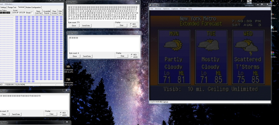
Transmitting/drawing the image byte-by-byte to framebuffer memory yields this:
![]()
Perfect! we can get an image into the framebuffer. So at least that experiment worked. I started drawing at $0x400000 in RAM with that image, and voila.
Ignore all the hex on the left, thats from experimentation of raw commands to the framebuffer control CPU, etc.... one of those commands transmits the palette. Which brings us to the next part.
The Palette. As explained above, all values sent to the framebuffer control CPU must be in RGB666 format. So you could leave the palette on the computer as 888 and do the conversion on the fly, or, you can convert the file as it is and send it straight. But the latter of the two options makes it hard to edit the file using a color picker tool. So i opted to keep all my file formats as RGB888, and when the palette is being transmitted to the unit, it performs the integer division at that point in time.
Sub LoadPalette(Filename As String, RGB666 As Boolean) As String()
	'Load Palette
	Dim ImagePalette(256) As String
	Dim PaletteString As String = File.ReadString(File.DirAssets, Filename)
	ImagePalette = Regex.Split("#", PaletteString.ToUpperCase)
	If RGB666 = True Then 'Convert our Palette into RGB666 from RGB888.
		Dim PaletteR As Int
		Dim PaletteG As Int
		Dim PaletteB As Int
		For I = 0 To ImagePalette.Length-1
			PaletteR = Bit.ParseInt(ImagePalette(i).SubString2(0,2), 16)
			PaletteG = Bit.ParseInt(ImagePalette(i).SubString2(2,4), 16)
			PaletteB = Bit.ParseInt(ImagePalette(i).SubString2(4,6), 16)
			If PaletteR > 0 Then PaletteR = PaletteR / 4
			If PaletteG > 0 Then PaletteG = PaletteG / 4
			If PaletteB > 0 Then PaletteB = PaletteB / 4
			ImagePalette(i) = Rgb2Hex(PaletteR, PaletteG, PaletteB).ToUpperCase
		Next
	End If
'	Dim Longpalettestring As String
'	For I = 0 To ImagePalette.Length-1
'		Longpalettestring = Longpalettestring & ImagePalette(i).SubString2(0,6)
'	Next
'	File.WriteString(File.DirApp, "palette.txt", Longpalettestring)
	Return ImagePalette
End Sub
Code snippet of my palette file loading tool.
	Dim ImagePalette() As String = LoadPalette("Extended_Forecast.pal", True)
	Dim Longpalettestring As String
	For I = 0 To ImagePalette.Length-1
		Longpalettestring = Longpalettestring & ImagePalette(i).SubString2(0,6)
	Next

	astream.Write(Convert.HexToBytes("00150301000301" & Longpalettestring.ToUpperCase & "024F5F0803601C83F0000003F0000003F0"))
End Sub
This simply reads the palette file using the above subroutine, and then sends it over the arduino to the FIFO for the framebuffer control CPU. This is the command that sets up the framebuffer options with te correct palette.
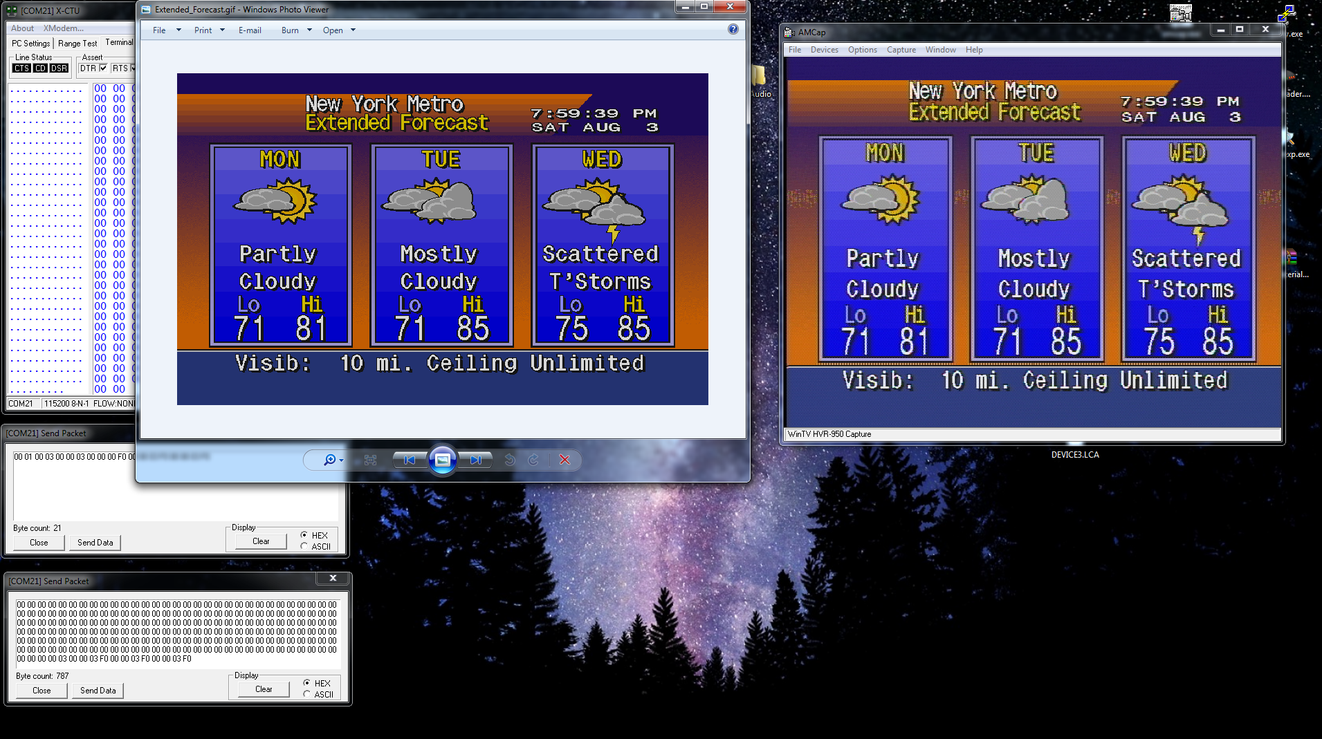
Given any luck, we end up with this:
![]()
Now we have the correct colors! Sort-of. There is a problem here. so... uh oh.
On to the next part!
-
First signs of life
03/27/2021 at 20:52 • 0 commentsSo now that we have basic framebuffer commands out of the way, Next thing we need to do is figure out the Memory-to-Pixel layout of the framebuffer.
I will spare you the experimentation process to get to where I have, plus its been a couple of years so I don't remember all the details anyways.
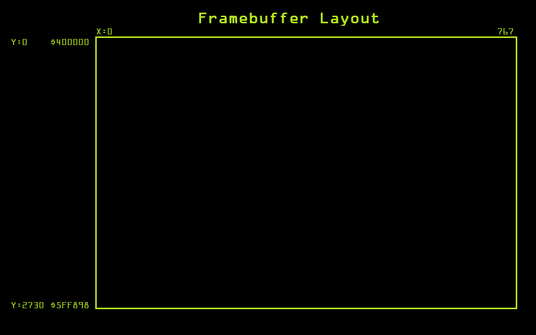
But the jest of it is this:
![]()
So now that we have this information, the next thing to do is figure out how the colors work.
So basically, each pixel is 1 byte. Since it is a 256-color system, this makes sense. However, 0 is reserved as the key color. So if there is a video signal coming into the unit, 0 gets replaced with 1 pixel of video information instead of a color.
All the other index values of 1 to 255 are physical colors. This color information is sent from the framebuffer control CPU to the RAMDAC.
There is a default palette as explained earlier, but you can also send a custom palette. We arnt quite there yet.
For now, lets see if we can get something into the framebuffer, regardless what it is. Before we can figure out exact details on some of the framebuffer control commands, we need have something on screen to use as a base of reference for experimentation.
So we have already played with colors, lines, etc... But we need to move on from that. We need to draw text and images.
But alas, all this stuff has to be recreated from scratch because none of it exists anymore. Except: the Font. For now, I was able to extract the font from the Weather STAR Jr. The font is almost 100% identical with the exception of the lower case W. it is not the same. So its from the same family, but not the same exact flavor. I am not a font/typeface expert so i dont know what all the little differences mean. but, hey. at least now we have something to start with.
There are public recreations of the WS4000 fonts, but they are far from accurate, and, they are true-type and the modern graphics suites have issues properly rendering fonts at low resolutions for bitmap use. so I abandoned that idea. Looks like garbage.
First of all we need to get the font in a format that the graphics card is going to work with. For testing, it was simple enough to just to convert the font into a simple bitmap with different values representing the different colors to be displayed on screen. Yes, this takes up a lot of memory. because now you are using 1 byte per pixel in the font table. But its good for testing.
So now I needed to write a simple program to shove data out of the UART to the Arduino for sending images/fonts.
Once I got a rough skeleton setup something like this:
	'Load 18x36 Font into Pixel Memory.
	Dim img As Image = fx.LoadImage(File.DirAssets, "font2.gif")
	Dim buffer() As Byte = GetPixels(img)
	Dim width As Int = img.Width
	Dim height As Int = img.Height
	For x = 0 To width - 1
		For y = 0 To height - 1
			Dim i As Int = y * width * 4 + x * 4
			Dim b As Int = Bit.And(0xFF, buffer(i))
			Dim g As Int = Bit.And(0xFF, buffer(i + 1))
			Dim r As Int = Bit.And(0xFF, buffer(i + 2))
			Dim a As Int = Bit.And(0xFF, buffer(i + 3))
			If A = 255 And R = 127 And g = 127 And b = 127 Then 'This is a Gray color (We key this out with whatever is in the background, So save as a 0)
				PixelArray(x, y) = 0
			else if A = 255 And R = 0 And b = 0 And G = 0 Then 'We have a black color. So we make this black, or 1.
				PixelArray(x, y) = 1
			Else if A = 255 And R = 255 And G = 255 And B = 255 Then 'We have a white color. So this is the typeface color. or, 2.
				PixelArray(x, y) = 2
			End If
		Next
	Next

	'Load 18x18 Font into Pixel Memory.
	Dim img As Image = fx.LoadImage(File.DirAssets, "font3.gif")
	Dim buffer() As Byte = GetPixels(img)
	Dim width As Int = img.Width
	Dim height As Int = img.Height
	For x = 0 To width - 1
		For y = 0 To height - 1
			Dim i As Int = y * width * 4 + x * 4
			Dim b As Int = Bit.And(0xFF, buffer(i))
			Dim g As Int = Bit.And(0xFF, buffer(i + 1))
			Dim r As Int = Bit.And(0xFF, buffer(i + 2))
			Dim a As Int = Bit.And(0xFF, buffer(i + 3))
			If A = 255 And R = 127 And g = 127 And b = 127 Then 'This is a Gray color (We key this out with whatever is in the background, So save as a 0)
				PixelArray2(x, y) = 0
			else if A = 255 And R = 0 And b = 0 And G = 0 Then 'We have a black color. So we make this black, or 1.
				PixelArray2(x, y) = 1
			Else if A = 255 And R = 255 And G = 255 And B = 255 Then 'We have a white color. So this is the typeface color. or, 2.
				PixelArray2(x, y) = 2
			End If
		Next
	Next

	'Turn 18x36 Pixel Map into a Character Array.
	Dim Characterbyte() As Byte
	Dim newI, b, A, c, newx, newy As Int
	For newI = 0 To 95 Step 1
		A = 0
		B = (newI / 16) + 1
		C = newI Mod 16
		Characterbyte = GetCharacter(c, b) 'Get character pixel data for ASCII Code I
		For newy = 0 To 35 Step 1
			For newx = 0 To 17 Step 1
				'Log("I" & newI & "X" & newx & "Y" & newy)
				ASCIIArray(newI, newx, newy) = Characterbyte(a)
				A = A + 1
			Next
		Next
	Next

	'Turn 18x18 Pixel Map into a Character Array.
	Dim Characterbyte() As Byte
	Dim newI, b, A, c, newx, newy As Int
	For newI = 0 To 95 Step 1
		A = 0
		B = (newI / 16) + 1
		C = newI Mod 16
		Characterbyte = GetCharacter2(c, b) 'Get character pixel data for ASCII Code I
		For newy = 0 To 17 Step 1
			For newx = 0 To 17 Step 1
				'Log("I" & newI & "X" & newx & "Y" & newy)
				ASCIIArray2(newI, newx, newy) = Characterbyte(a)
				A = A + 1
			Next
		Next
	Next
The above code basically loads up my Font Table which is a single image. Into memory. I laid out the font as a single indexed color GIF, and this program brings it into a bitmap font table. This is a Java/B4J program for ease of use. its very VB6-like.
At this point, I can write a simple piece of code to write a random character glyph into the framebuffer and see what happens.
The subroutine I wrote which draws a character into the framebuffer, like so:
Sub DrawCharacter(Text As String, Start As Int, Line As Int, StartAddress As Int, Background As Int)
	'Write a character to the screen:
	Dim Fontval As Int
	Dim CMD(6) As Byte
	Dim AddressBytes() As Byte
	'Beginning of framebuffer memory
	'Dim Address As Int = 0x402716
	Dim Address As Int = StartAddress
	Dim Columnaddress, Lineaddress, I, A, B As Int
	Dim Textbuff As String

	'Arduino Packet format for Byte-Wide Memory Writes:
	'02 = Write Byte
	'XX, XX, XX, XX = Address (Little Endian)
	'Data Byte = Little Endian.

	'Arduino Packet format for Word-Wide Memory Writes:
	'03 = Write Word
	'XX, XX, XX, XX = Address (Little Endian)
	'XX, XX = Dataword (little Endian)


	'Calculate a new address based on the Specified start character position, and line.
	A = (Line * 36) * 768 'Calculate new character line position
	B = Start * 18 'Calculate new character position
	Address = Address + A + B 'Create the new address

	Dim Characterbytes() As Byte = Text.GetBytes("UTF8") 'Get our character array.
	For I = 0 To Characterbytes.Length-1 'Loop through each byte in the character line.
		If Characterbytes(I) >= 32 Then
			Fontval = Characterbytes(i) - 32'Re-align ASCII table to exclude non-printable characters (Doesnt exist in this font)
		Else
			Fontval = 0
		End If

		Textbuff = ""
		Lineaddress = Address
		For Y = 0 To 35
			Columnaddress = Lineaddress
			For X = 0 To 18
				'CMD(6) = ASCIIArray(Fontval, x, y) 'Load in left pixel
				'x = x + 1
				CMD(5) = ASCIIArray(Fontval, x, y) 'Load in right pixel
				AddressBytes = Convert.HexToBytes(Bit.ToHexString(Columnaddress)) 'Get the byte values
				CMD(0) = 2
				CMD(1) = AddressBytes(2)
				CMD(2) = AddressBytes(1)
				CMD(3) = AddressBytes(0)
				CMD(4) = 0
				If CMD(5) = 1 Then CMD(5) = 127
				If CMD(5) = 2 Then CMD(5) = 12
				If CMD(5) = 0 Then CMD(5) = Background
				'If CMD(6) = 1 Then CMD(6) = 15
				'If CMD(6) = 2 Then CMD(6) = 1
				'If CMD(6) = 0 Then CMD(6) = Background
				astream.Write(CMD)
				Columnaddress = Columnaddress + 1 'Advance to the next pixel
			Next
			Lineaddress = Lineaddress + 768 'Move to the next line
			Log(Textbuff)
			Textbuff = ""
		Next
		Address = Address + 18 'Advance to next character position
	Next
End Sub
Great. This should do the trick. (All the debugging has been done, I dont have my old old code from this time period)
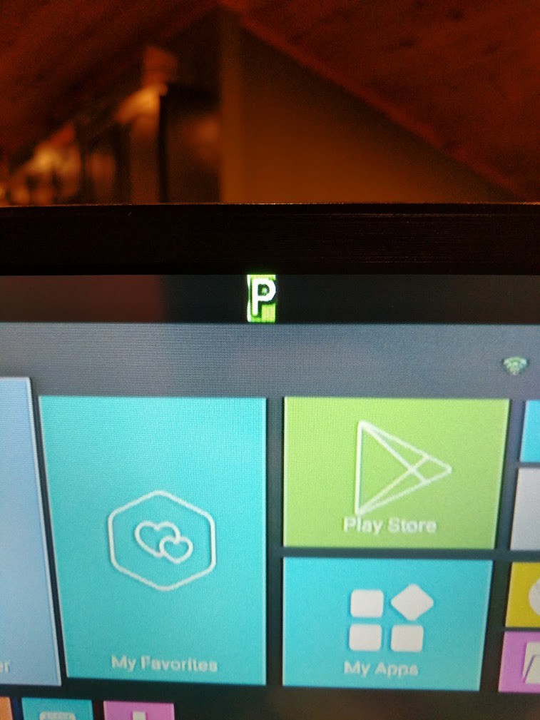
So in theory, if I draw a P into framebuffer, we can do it like this:
DrawCharacter("P", 0, 0, 0x400195, 9)Run the above subroutine, and boom:
![]()
Its not perfect, you can see the characters aren't properly aligned, this is due to some weird bug in my Arduino 68K emulation code. its doing some weirdness with that.
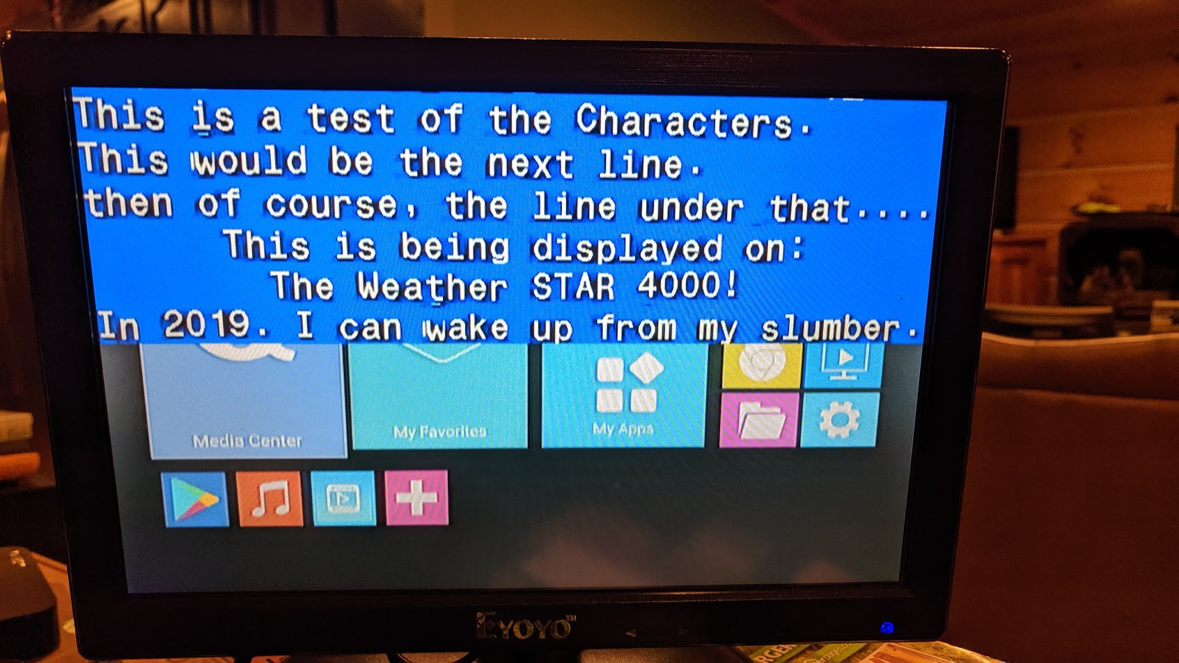
Now lets see if we can draw out a full string:
DrawCharacter("This is a test of the Characters. ", 0, 0, 0x400000, 9) DrawCharacter("This would be the next line. ", 0, 1, 0x400000, 9) DrawCharacter("then of course, the line under that.... ", 0, 2, 0x400000, 9) DrawCharacter(" This is being displayed on: ", 0, 3, 0x400000, 9) DrawCharacter(" The Weather STAR 4000! ", 0, 4, 0x400000, 9)![]()
Boom! we now have the the primitives of the framebuffer figured out!
Lets move onto the next thing....
-
Framebuffer Control
03/19/2021 at 22:38 • 0 commentsSo now we have a basic way of hacking/testing the graphics card independently from everything else, Now its time to experiment with the Framebuffer control...
To do this, we need to study the 8031 ROM in much finer detail to figure out what it all does.
So I stared at this ROM and picked it apart for hours on end, over the span of multiple days.
I toyed around with one command at a time just to try and get a handle on whats going on.
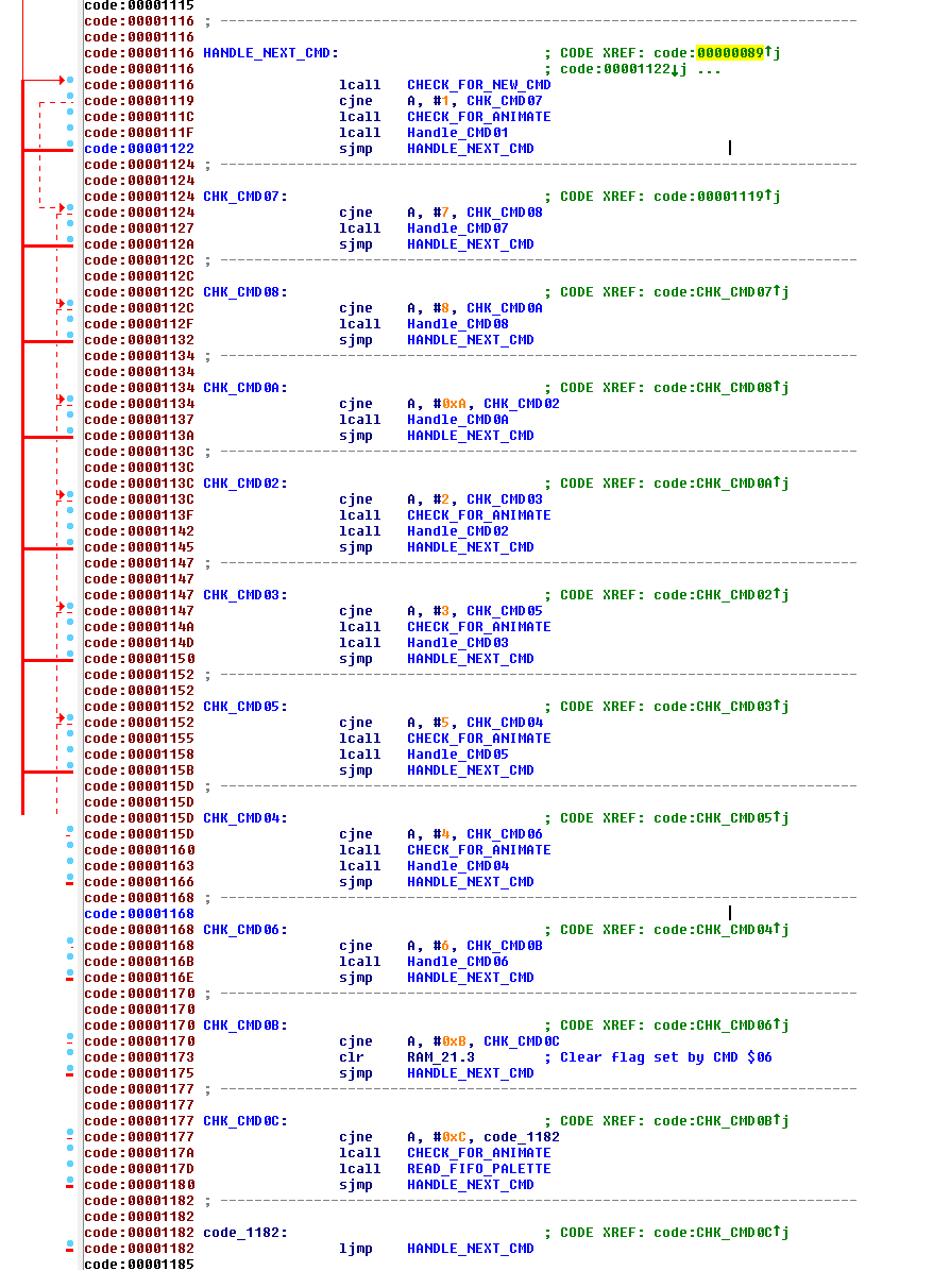
So in ROM, there is a Compare/Jump table that checks for a byte waiting in the FIFO. Once it sees a byte, it reads it and then does the "select case" to figure out what to do next based on the value of the byte sent. This is the command.
This is the command table that I have figured out and made comments on:
![]()
Now this ROM is commented out already based on what I knew, its still not 100% complete but its good enough for me to be able to do what I need to do. Commenting was easy enough to do once I figured out the address map of the 8031 on the graphics card, where everything resides. (those details can be found in the MAME driver for now, i may post that info later, but its not relevant to this article).
So at this point, its pretty much just throwing commands at it with parameters and see what sticks to the wall, or what explodes. One of my favorite cheesy movies from the mid 90s "Hackers", the quote from Joey basically. "Its like choice". Throw commands at it, and see what happens.
It isn't going to spit cash out in the middle of the street in bumsville Idaho though. Sorry. :-)
In order to do this, I had to setup my Arduino code so I could simply send serial hex data straight to the FIFO. one byte at a time, this makes it easier to experiment and just throw data at the framebuffer control to see what happens.
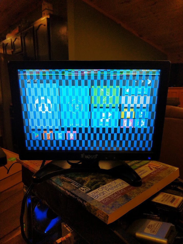
Now, since I never kept a blog in real-time as I was experimenting with this thing, I don't remember detail for detail what I did and what each image actually was. But I will post the images and video clips below for posterity of my primitive experiments.
![]()
This is when i drew some lines into framebuffer, and then I was able to send a control command that switches the resolution.
This thing has a default color palette built into ROM that gets loaded on reset, so all these experiments are showing off the default palette.
Here is a link to the Photos Album of the images and video clips of my experimentation process:
https://drive.google.com/drive/folders/1qG0t9QqQU80TEbdAN7haOULnQleJFpNM?usp=sharing
Basically, I determine the crawl, roll, page switching, etc commands but not yet their math or specifics. Without drawing things into framebuffer, I cant really figure out the fine details just quite yet.
That's in the next installment. Stay Tuned....
-
Probing the Graphics Card
03/17/2021 at 00:03 • 0 commentsSo now comes the real hacking part.
We have the basic Architecture of the graphics card now, but we have Zero idea how this card works. or even how to speak with this card, or do anything with it yet.
At the time, I did not understand 68K ASM or C that well yet, so I needed to figure out an easier way to probe this card and be able to do things.
Enter Arduino (once again).
I decided to remove the MC68010 CPU, and then use an Arduino Mega in its place to "emulate" the 68K bus cycles, this would allow me to write a much higher level program on the PC side and communicate over USB to the Arduino and be able to send commands and access addresses on the card.
This should help me figure out how to control the framebuffer, how the framebuffer is laid out, etc...
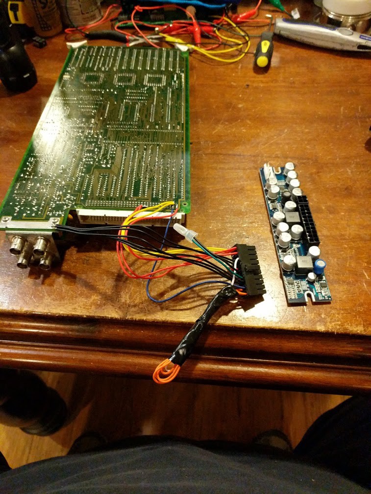
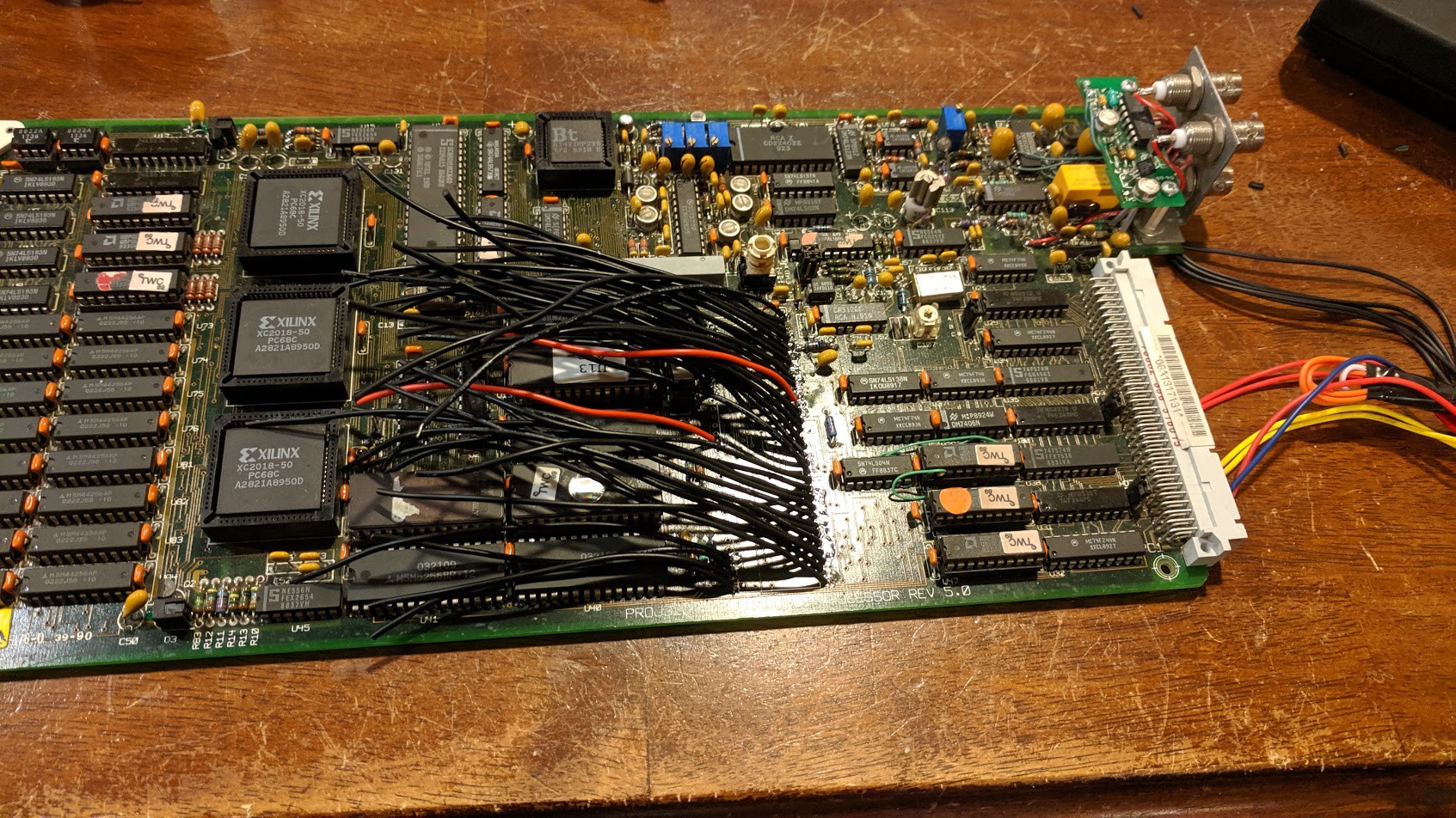
Wiring up a PicoATX Power supply. (This helps me run this card separately from the unit)
![]()
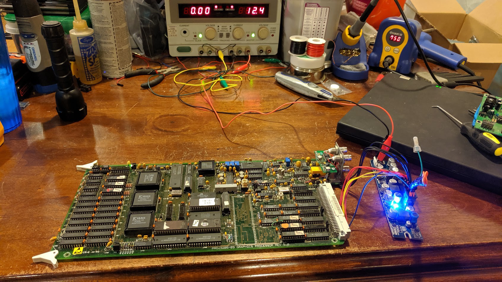
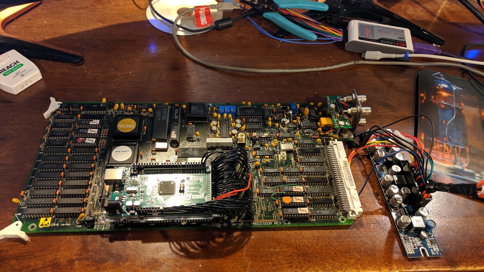
Powering it up on the bench to make sure things dont explode. Magic smoke test:
![]()
And... yeaahhhh.. :-/
![]()
![]()
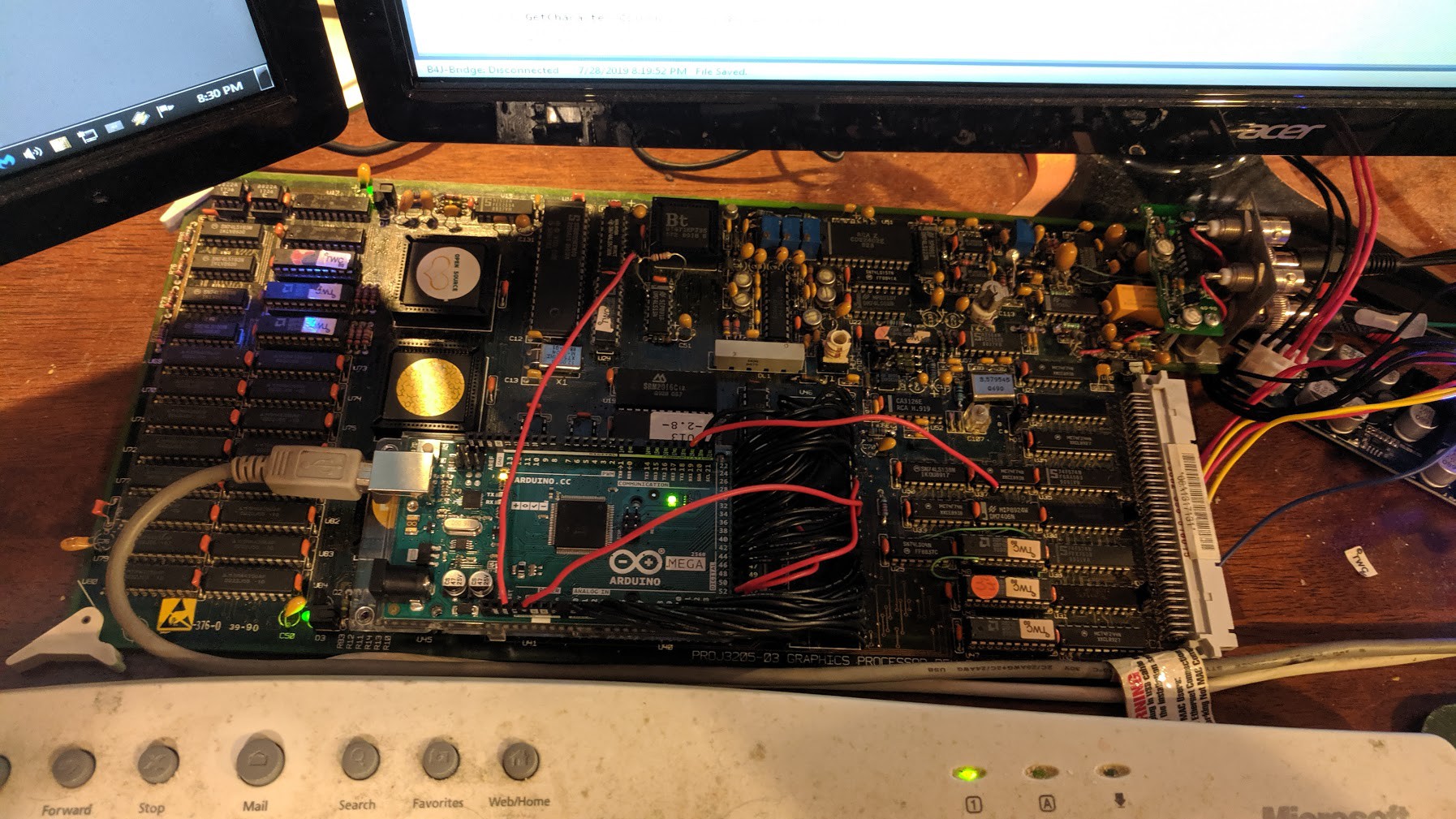
Arduino is all mounted up and ready to go.
Now, I still have to write a test program that runs on the Arduino to keep the watchdog reset on this graphics board. I know once I do that, my bus emulation program is working :-)
The green LEDs on this board are the "health" indicators. They will remain green as long as the watchdog is reset.
![]()
And Success! the 68K's health light is on, and my program is running.
Now I have a good setup for probing the graphics card to learn about how it works, and its operations.
Next thing we need to do is start writing things in the Framebuffer memory location and see what shows up on screen. Also, we need to study the 8051 ROM in order to grasp how the framebuffer works.
Turns out, it took experimenting with the commands plus studying the ROM to figure out how everything works.
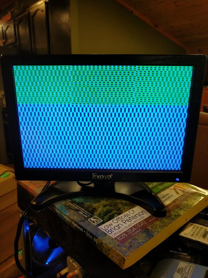
![]()
Aaaaand there we go! I simply drew some stuff in the framebuffer memory, and displayed its initial contents. That "checkerboard" pattern is the initial state of DRAM when first powered on, and nothing being written yet. However it still doesn't look right. instead of a clean color, its a broken alternating line. Turned out, one of my wires was loose on the Arduino. Not surprising with that ratsnest.
-
MAME: A potential path?
03/15/2021 at 17:18 • 0 commentsI am posting this completely out of order, but it's something that needs to be said. I have been seeing some comments pop up about MAME and how there is co-development on reverse engineering the 4000 going on.
This isn't true. Well, partially isn't true. I did get the ball rolling though. Getting it working in MAME vs Reverse Engineering the hardware are two very different things here.
I got a MAMEdev involved for what I thought was to help me develop software and be able to debug/trace it without trying to do something wonky on the original machine. But I was mistaken here, I actually contacted the MAMEdev to see if it was possible to make a 4000 emulation inside MAME, so I could attempt to step-through and trace the ORIGINAL ROMs. I was still very new to 68K. Kinda still am, but I have the basics down.
It was easier at the time for me to figure out what each instruction was doing in the ROM to get a better understanding of what is going on, but eventually I decided against persuing that avenue for now. Maybe I would circle back around to it later.
Plus, I still didn't know all the fine details yet to finish up the emulation driver for MAME. I still don't "entirely" know how the framebuffer works, but I know what all the commands do now. (I will get into these later).
I would actually like to circle back around eventually and get MAME working. Someday..... my projects list is getting more full by the minute :-/
I know this may sound like I am feeding the trolls, but it must be said. Here is my conversation with a MAME developer on the subject, including me sending him all my notes and schematics so he could write the MAME driver:
![]()
![]()
![]()
![]()
Sorry for all the drivel, but I had to clarify the data here, and the real information as to what went on. Why? I suppose to try and prevent as much mis-information as possible.
For accuracy purposes. I stand by my decision for letting MAME in on this as well, I think it will be a useful tool to messing with the 4000's ecosystem.
Now, back to our regularly scheduled programming...
-
Architecture: Graphics Card
03/14/2021 at 00:14 • 0 commentsWith the architecture of the main system out of the way, my biggest focus at this point was the Graphics card itself. and figuring it out.
Since as I have stated before, if we cant figure out the graphics card, in a graphics machine, we are hosed before we even start.
So... Once again we perform what we did with the CPU card, analyze the PALs to figure out the memory addressing of the graphics card.
Like so:
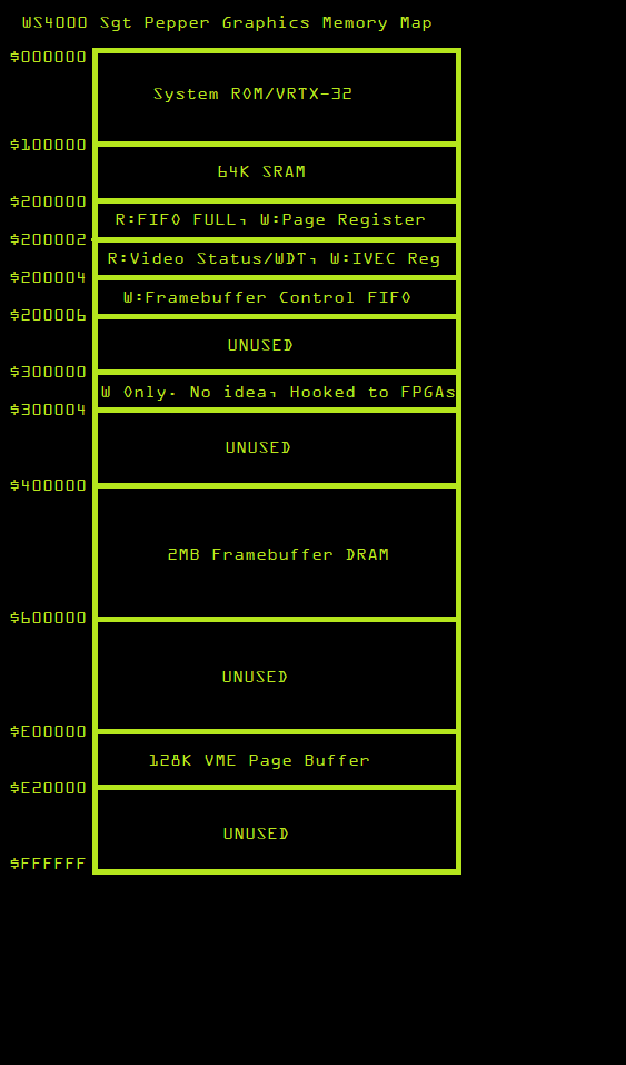
![]()
This is basically the memory map of the Graphics board. If you noticed from the previous articles, the main CPU does not have access to, nor can directly access the Graphics card's memory space.
The graphics card has its own memory space. So the only way to communicate between the main CPU and graphics CPU is through the doorbell interrupt to the graphics card, and shared memory space on the VME Bus. (Main CPU Bus).
The other thing to keep in mind here is how the Graphics card accesses the main system bus. it does so through a Write Only paging register, and a 128K paging buffer. Since the Paging register is write-only, it cannot be read or its state saved! Therefore, extra precaution has to be taken when using the system bus in a multitasking operating system. Ideally, a Mutex.
![]()
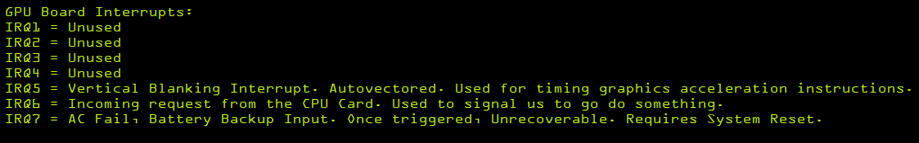
Interrupts are fairly simple on this card. Nothing special, there is a Vertical interrupt, and the Doorbell interrupt from the main CPU.
If you look at the memory map, this card is manually vectored. So you would load the IVEC register with the appropriate interrupt vector number, and then trigger the IRQ back to the main CPU card. with any 68K system, you could have multiple ISRs to handle different things. This is necessary for inter-process communication between the two cards.
Framebuffer:
The Framebuffer RAM is standard DRAM. This RAM's access is interleaved between the pixel clock/rasterization logic, and the main CPU. So the CPU access to this RAM is "vampire" or bottlenecked. One of the biggest bottlenecks in the WS4000 system. the VME Bus paged-access is another one.
There is another CPU on the graphics card, and that is the intel 8031 (MCS51) that sits alongside the 68K. This is the framebuffer control CPU, and the communication between the 68K and this CPU is one-way only. through a FIFO. This too has to be under a Mutex lock. Otherwise, you can/will crash the CPU if you malform the command.
Stay tuned for more graphics card details and first signs of life!
-
The Architecture
03/13/2021 at 00:17 • 0 commentsNow that we have all the PAL logic dumped in a state where we can read it to figure out what's going on, we can proceed on figuring out the architecture.
However, there are a couple registered PALs that I don't have the logic for, and there are a few PALs I didn't bother getting the logic to, as it wasn't relevant to the mission at hand. However it might not be a bad idea getting it anyways in case the PROM inside a PAL ever bit-rots. Any cases of this happening? Please comment below. (I don't know).
July-August of 2019, I focused solely on the graphics card and its logic so I could further probe the card to figure it out. I will get to this soon, but instead of going in chronological order, lets go in order of architecture.
So after studying the logic and design of the CPU card circuit, we can make these conclusions:
the CPU card is also the bus master. (of course). However, any card on the bus can request access to the bus, and the CPU card will grant it, allowing other peripheral cards to gain access to the bus. Usually this is done for DMA reasons. The cool thing? if the CPU card grants bus access, the CPU can still access its own 2MB of RAM at $0, as well as the ROM, etc... and continue to execute code as long as it doesn't need the rest of the bus! kinda neat.
However, only the graphics card can be a bus-master in the system currently. All the other cards such as the I/O, and Data/Audio are slave-only devices that require communication through vectored interrupts.
We learned that this is a VMEBus-based system, Well... a variant of it. But the primary Address/Data bus is pinned the same as VME. However IRQ lines have been routed a different way as the decode logic is in the cards themselves instead of across the bus. so the IPL lines are not exposed across the bus. Just the IRQs themselves. They instead put a voltage on the 3 IPL pins, no longer making the system 100% VME Compliant. So as I mentioned earlier, don't go plugging in VME cards!
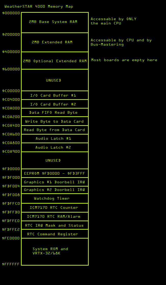
Memory Map:
![]()
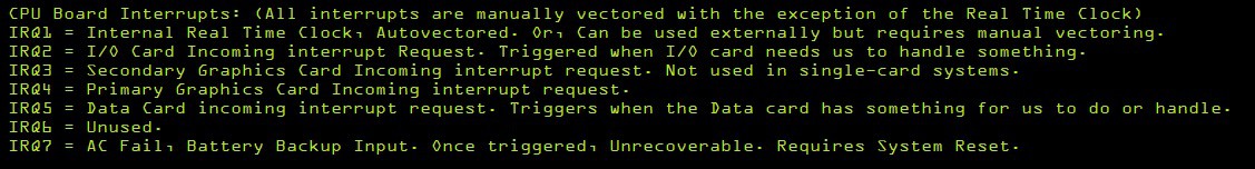
IRQ:
![]()
Now that was fun! (Actually, no. it took many hours)
Reverse Engineering The Weather STAR 4000
The Weather STAR 4000: A Journey of reverse engineering the hardware to an iconic machine of the 1980s/90s.