 Dilshan Jayakody
I2C is a popular data bus to communicate with inter-board peripherals. Today I2C based chips and modules are widely available in many categories, including data storage, ADC/DAC, I/O Expanders, sensors, etc.
The I2C master mode emulator allows communication with I2C devices by sending or receiving data to/from the I2C bus. To issue the I2C commands, the emulator should connect to a PC over the USB port. After initializing the emulator, the PC and directly control the I2C slave chip/module.
This emulator is base on ATmega16A MCU. The USB communication channel is develop using the V-USB firmware.
To simplify the assembly, the PCB of this emulator is designed on a single-side board. The dimensions of the PCB are 96.77mm × 110.73mm. All the parts used in this project are through-hole-type, generally available components.
This emulator needs an external power supply, and the recommended supply voltage is between 12V - 15V.
Control software and commands
The control software of the emulator is developed using libusb and tested only with Linux operating systems. The current firmware and control software support I2C emulation on 100kHz, 250kHz, and 400kHz clock rates.
Following commands are available for the I2C test terminal:
- init - To initialize the I2C bus with the given clock rate.
- start - Issue START condition to the I2C bus.
- stop - Issue STOP condition to the I2C bus.
- write - Write given byte value to the I2C bus.
- write-address - Set slave address with read/write flag.
- read - Read data byte received from the slave device.
- output-voltage - Command to set the output voltage to 5V or 3.3V.
- reset - Reset emulator and I2C bus.
- exit - Exit from the terminal application.
- help - Display help screen.
All the above commands are explained in the project documentation at the GitHub repository.
I2C test terminal has an auto-complete command prompt. To use this option, press the TAB key twice on the command prompt.
Before launch the terminal control application, the I2C Emulator device must connect to the PC and needs to power up.
Emulator test setup
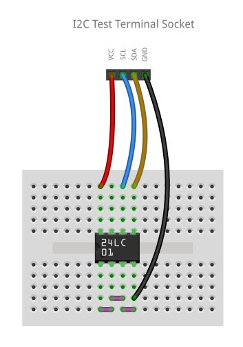
The below diagram illustrates the simple layout to test the I2C terminal. In this layout I2C terminal is connected to the 24LC01 Serial EEPROM IC.
The basic test performs with the above setup are listed below:
I2C Terminal - Copyright (c) 2021 Dilshan R Jayakody. (jayakody2000lk@gmail.com)
Type "help" to list down the available commands. Enter "help [COMMAND]" to get the information about the specific command.
Current I2C output voltage: 3.3V
> init 100
> start
A START condition has been transmitted.
> write-address 0xA0
Slave address with WRITE flag has been transmitted, ACK has been received.
> write 0
Data byte has been transmitted, ACK has been received.
> write 0xAB
Data byte has been transmitted, ACK has been received.
> write 0xCD
Data byte has been transmitted, ACK has been received.
> write 0xEF
Data byte has been transmitted, ACK has been received.
> stop
> start
A START condition has been transmitted.
> write-address 0xA0
Slave address with WRITE flag has been transmitted, ACK has been received.
> write 0
Data byte has been transmitted, ACK has been received.
> start
A repeated START condition has been transmitted.
> write-address 0xA1
Slave address with READ flag has been transmitted, ACK has been received.
> read ack
Data byte has been received, ACK has been returned.
Data: 0xab
> read ack
Data byte has been received, ACK has been returned.
Data: 0xcd
> read ack
Data byte has been received, ACK has been returned.
Data: 0xef
> read nack
Data byte has been received, NOT ACK has been returned.
Data: 0xa1
> stop
> exit