LiFePO4wered BMS
Battery Management System for next gen LiFePO4wered projects
Battery Management System for next gen LiFePO4wered projects
To make the experience fit your profile, pick a username and tell us what interests you.
We found and based on your interests.
With the pack built, it was time to test. The first thing I noticed was that the pack had no output voltage. This is normal because while building it, you can't really attach both cells at the same time, so the protection chip decides that one of the cells is low/missing and turns the output off. The condition is cleared by providing some charge current to the pack. At that point I saw 6.6V on the JST VH connector.
Time to put the pack on my electronic load and put some load on it. The pack was designed for 4A max output. Let's start with a 2A load:
The thermal image shows a minor 4 °C temperature increase at the current sense resistor and dual MOSFET that disconnects the pack if there are issues. My calculations indicate that at this current level, the power parts would dissipate about 0.17W.
Let's crank it up to 4A load:
As expected, more heat at this load. But very reasonable! My calculations indicate that at this current level, the power parts dissipate about 0.7W. There's enough power dissipated that the pack warms up a bit, so comparing to the previous baseline, the temperature increase is about 26 °C. This is at ~24W output power!
There has to be some voltage drop across the current sense resistor and protection MOSFETs, resulting in some losses, because the pack protection chip uses this voltage drop to protect against over current and short circuit. The over current detection threshold is at 0.2V.
Since there are tolerances on the detection voltage, the current sense resistor and especially the RdsON of the MOSFETs, the component selection was done to end up with a over current detection range of 4A - 5A. The goal is for the threshold to be above the maximum advertised current (4A) and the maximum current supported by the cells (5A). My prototype pack had protection kick in at 4.6A.
I let the pack run down to empty to check the under voltage cutoff. I had specifically made the pack with some cells that I had abused before to have some differences between the cells. If one cell has less capacity than the other, it's easier to observe that the protections work correctly. In this case, one cell reached 2.0V while the other one was still at 2.7V, and the pack correctly disconnected. Success!
At that point I started to charge the pack with my bench power supply at 7.2V with a current limit at 1.5A. Both cells quickly recovered to 3.4V. Near the end of charge, when voltage starts to increase again, I reduced the current limit to 0.2A because that's the level for which the balancing circuit is designed. Why only 0.2A? Because we are using passive balancing, we just burn off excess power to prevent one of the cells from being overcharged if the other isn't full yet. Because this may happen for instance in a outdoor box out in the sun in Arizona in summer, we don't want too much power to be dissipated for fear we get the cells too hot. With the current component values we dissipate 0.72W when balancing a cell.
Here is a thermal shot when one cell is full and passive balancing for it kicks in:
The temperature increases by 14.5 °C where the balancing resistor is located.
In this picture both balancers have kicked in:
This increases the board temperature by about 35 °C. Of course, having both balancers on is not really a mode that's normal if you're using a real charging chip. Both cells are full at this point and the charger is supposed to turn off. But my bench supply of course happily will keep sending 0.2A through the balancing resistors. :)
All basic pack protection functionality seems to work as expected! Very happy with the progress.
Once I had PCBs it was time to make a pack. I already had nickel strips and a spot welder from previous efforts, so that made things easier. I also got flexible silicone wire, JST VH terminals and housings and a crimper that works for JST VH.
First I soldered the wires and nickel strips on to the PCB:
Then I spot welded the nickel strip to two 18650 LiFePO4 cells:
As you can see, the components sit in the gap due to the radius of the two cylindrical cells to get a compact assembly that only takes up the space of two 18650 cells:
One of the parts you see at the end is an NTC thermistor. Since it's supposed to measure the temperature of the cells, the air gap is not ideal (although once the pack is wrapped, the air being trapped in the pack should improve things versus open air). I asked a manufacturer in China I'm talking to about mass producing these about filling the gap with some thermally conductive compound and they said it was possible.
A real battery pack would at this point be covered with foam end caps and wrapped in heat shrink, but since these are prototypes and I will likely be messing with them, I decided to leave that off for now.
So I've been working on this for a while already and am only now catching up in documenting it. I document it because it might be useful to someone but also because it tends to be useful to myself, if I need to check back later on what exactly happened, when, or why I did things a certain way.
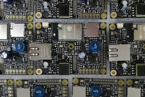
I think it was last week that my prototype PCBs and parts for the first 2S LiFePO4 BMS arrived and this effort really started to accelerate. Here are some pictures of the prototype build:
This was a small panel with 5 identical circuits (3 left in the bottom picture).
Each circuit has roughly two parts to it: on the right there is the fairly standard pack protection and balancing. It uses two HY2212 chips with MOSFETs and 18Ω resistors to burn off excess energy if a cell reaches 3.6V. The resistor value makes it so only 200 mA can be burned off, to keep resistor wattage/cost and heat generation in check. This means that when we reach that point, the charger should only try to put in 200 mA max, because otherwise the cell will still get the remaining current. So the charger has to take part in this for it to work. Then there's also an HY2122 chip which takes care of protecting the pack from over voltage, under voltage, over current and short circuit. It uses Q1, a dual, drain connected MOSFET to turn charging and discharging on and off. It normally measures the voltage across this dual MOSFET to determine current limits, but I decided to have lower RdsON MOSFETs and add resistor R1 to make these limits more predictable since RdsON of MOSFETs can vary quite a lot and the limits depend on the total resistance. As you can see, I messed up the part I bought so there's a 2010 size resistor where there should be a 1210. Oh well, it still fits. :)
The left side of the circuit is where most of my "special sauce" is. The SO8 chip is a Padauk PMC131 microcontroller, which implements the 1-wire digital interface in software, contains the pack ID data and can measure the two NTC thermistors. Yes, I admit it, I like these little Padauk micros. I used one very effectively in my #wESP32. This one has a little more oomph and costs a little more than the 3¢ PMS150C that made them famous, but you still get a lot of value for the price. In this case, a 12-bit ADC and -40°C to 85°C temperature range.
To be honest, I had some trouble making the 1-wire protocol work in this chip. Unlike some other protocols, 1-wire is very dependent on timing, with a 1 being a short pulse and a 0 a long pulse. It took a good deal of optimization to make everything execute fast enough. I also ran into an issue because I was testing the code using a MicroPython 1-wire host running on a Raspberry Pi Pico, and it turns out that the timing of the MicroPython onewire library is just wrong. It doesn't respect the minimum bit slot time of 60 μs. It also doesn't wait for a low bus to be released before it starts pulling it low for the next bit, but just clobbers through what the slave is doing. I forked the code, fixed it and flashed my own version and then it worked. I should do a pull request to get this fixed upstream, but the fact that there are currently 377 open pull requests doesn't make me feel optimistic that it would be useful. I should still do it though.
R7 on the far left and R8 next to the balancing resistors are both NTC thermistors that are measured by the micro, and their value in a resistive divider can be read over 1-wire. I have two of them to hopefully be able to tell more about the pack state. R7 is far from the balancing resistors and R8 is right next to them so I hope to be able to tell from the temperature gradient when one of the balancers kicks in.
The components and wiring pads are all clustered toward the center of the PCB because I want them to face inward and end up in...
Read more »When I started this project, I started by talking to some Chinese folks who are in the business of making battery packs. I'm new to that side of the business, so I wanted to learn as much as I could. One important thing was to figure out the type of cells available.
I have always felt like a pack made with round cells seems like it's a bit of a waste of space. There are always empty gaps between the radii of the cells. So I started by telling them that I was looking to make a small 2S LiFePO4 pack, and I would like them to find suitable cells. And if possible, I would like LTO cells of a similar size , so that I could make a 2S LiFePO4 pack with similar physical dimensions as a 3S LTO pack.
I never found anyone who could help me with this. Oh, if I would order 30000 of them, they could make a custom cell for me, but below that volume, forget it. Unfortunately, my business isn't at that volume, yet. ;)
At that point I was like: "Oh forget about making a LiFePO4 and LTO pack of the same size, what size LiFePO4 cell do you have that would work for me?" I was sent some options, but to be honest, options were limited. Turns out LiFePO4 cells are more often made in larger sizes than smaller sizes, to make car batteries, golf cart and electric bike systems, things like that. High power stuff. Then I requested specs for the few cells they could offer me in smaller sizes, I was in for a surprise when I did some calculations.
I calculated the capacity of a pack per unit of volume (energy density) for a pack made with the pouch cells I got specs for versus one made with 18650 cells, and was surprised to find that the energy density of the pack made with 18650's was actually better than one made with pouch cells! That was completely unexpected. How can that be with all that wasted space? Well, I already knew there are cells optimized for energy and others optimized for power. I have always used the ones optimized for energy, and it turns out pretty much all LiFePO4 pouch cells are optimized for power, to be used in high power applications. I can't get any pouch cells optimized for energy it seems. So standard cylindrical cells are going to be the best for me it seems.
The good thing about that is that there are many factories that make them, so I won't be stuck with a single manufacturer. They exist for both LiFePO4 and LTO. If I want a pack that's equivalent in physical size between LiFePO4 and LTO, I make a 2S3P LiFePO4 and a 3S2P LTO (or multiples of that). Another benefit is that I already use 18650s so it makes things easy to prototype. And because they are pretty standard, it's easy to plan different capacity packs by using multiple cells in series and parallel. So in some ways, ending up back with standard 18650s has simplified this a lot.
This is an important development for my company. So I want to give it thorough thought because I may have to live with the consequences of decisions I make now for years to come. On the other hand, if this effort has taught me anything it is that there is such a thing as overthinking it. By trying to plan for everything, and think of everything that may ever be necessary, you end up just spinning your wheels and nothing ever gets accomplished.
So once I had done that for a couple of months, it was time to bring this back to reality. The first thing was to list what were important aspects to me from a high level, "platform" point of view. If I was now going to start making "LiFePO4wered" battery packs, what did I want from them? What did I want my customer's perception to be? Here are some important things I considered:
Create an account to leave a comment. Already have an account? Log In.
Become a member to follow this project and never miss any updates

 Patrick Van Oosterwijck
 jaromir.sukuba
 David Scholten