agp.cooper
-
Deblocking
05/31/2021 at 02:37 • 0 commentsDeblocking
I ran into this problem with my MyCP/M projects. The skeleton custom BIOS (cbios.asm) does not cover sector/block sizes other than 128 bytes. Unfortunately I did not read Chapter 12 (Sector Blocking and Deblocking) of the "CPM 2.2 Alteration Guide". So I was caught out. This was the reason I built Grant Searle's CP/M machine. So I could look at a properly working CBIOS. I thought it would be a good platform to prototype my FRAM "chip" disks (thus the expansion port on latest PCB).
This is still a good plan, I just have to learn Z80 assembler (MyCP/M is 8085 based).
Expansion Port
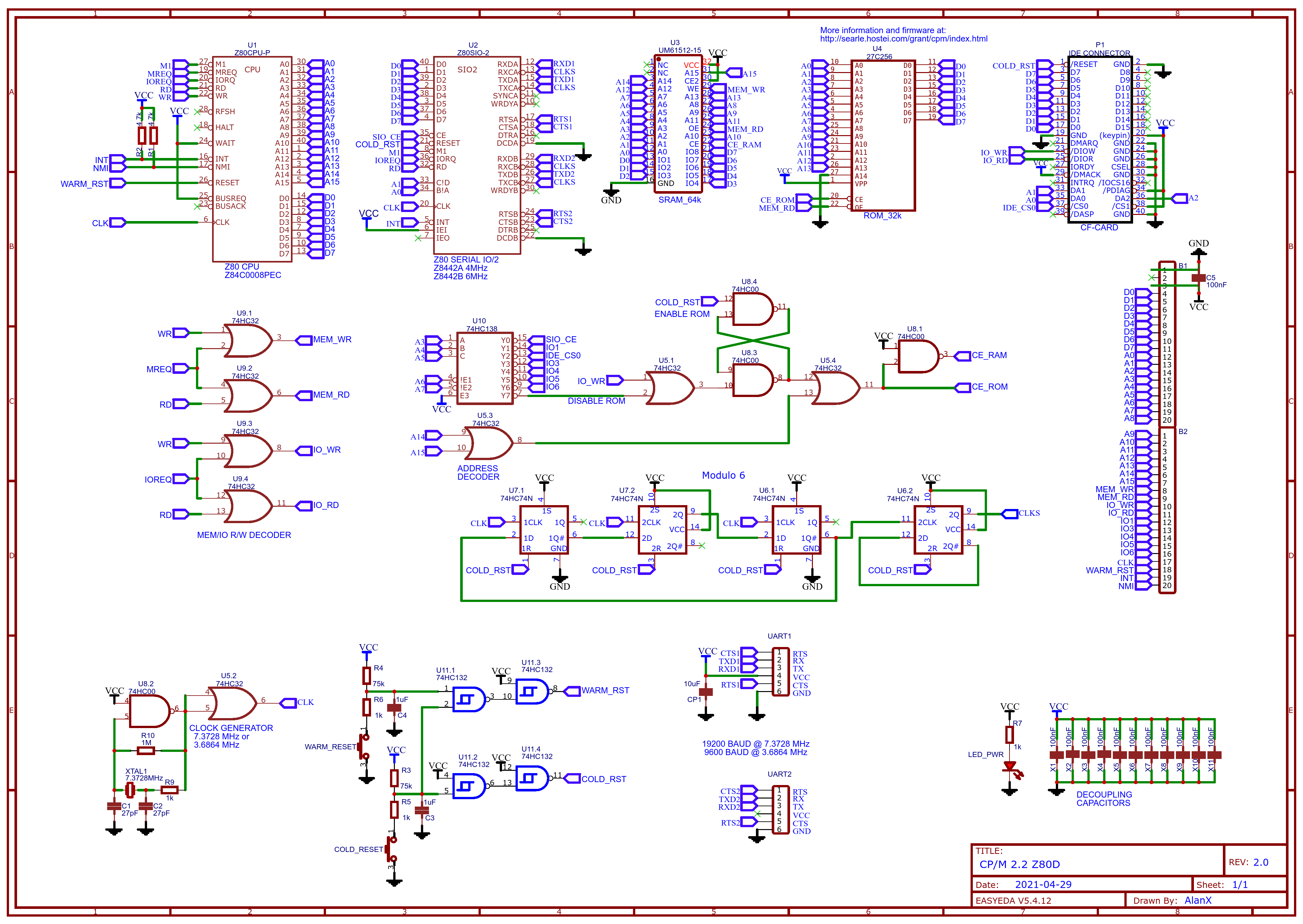
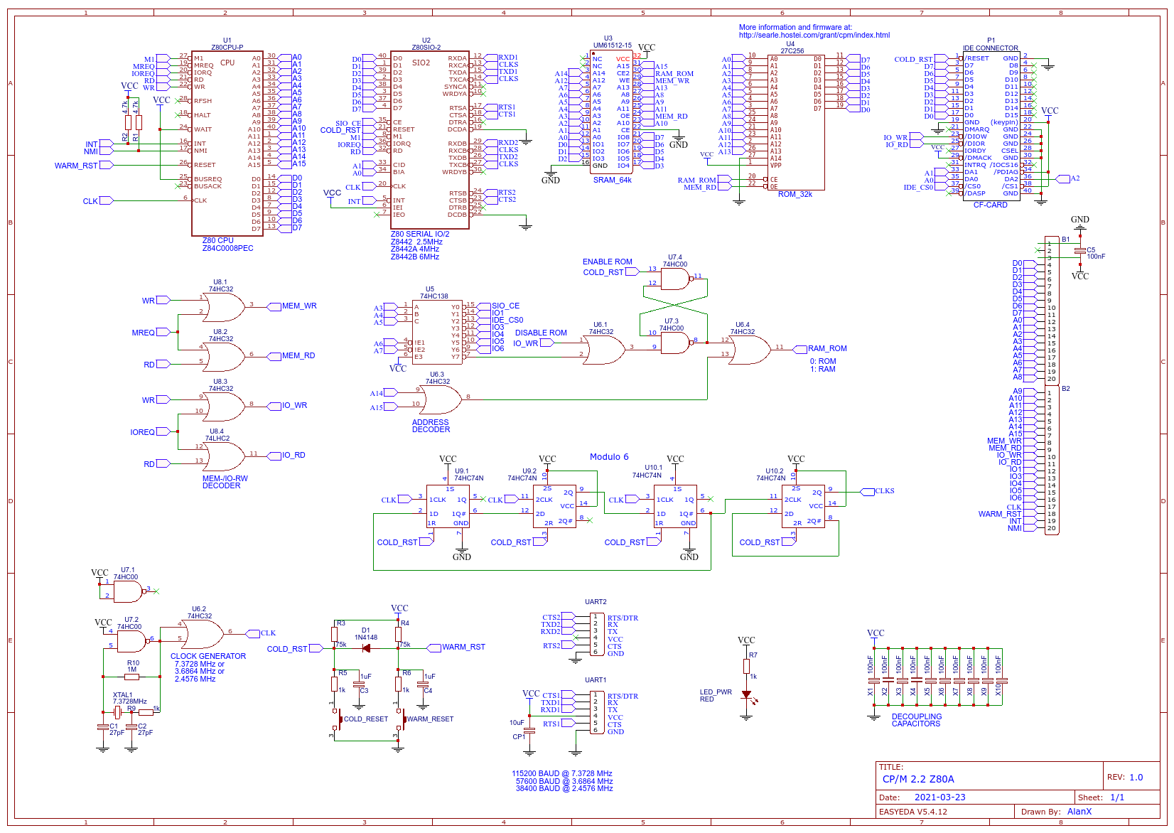
Here is the latest schematic:
![]()
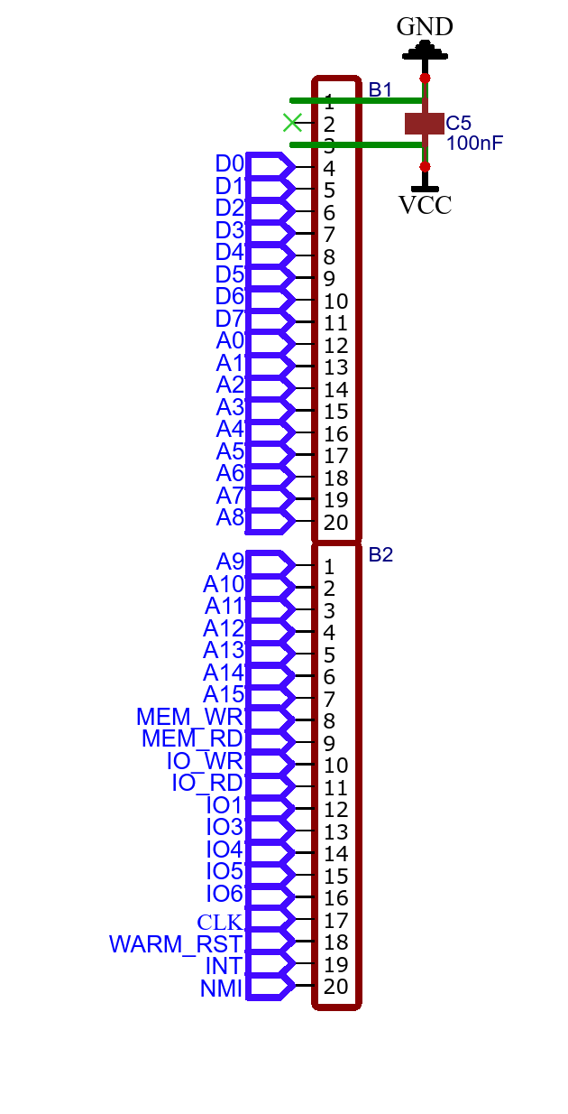
And the expansion port:
![]()
Unfortunately I access disk hardware partly via I/O space (i.e. disk and page selection) and memory address space (i.e. page data R/W). Grant Searle's access is all I/O space.
Okay, I can adapt. I can use IO1 for data space, IO3/4/5 address space.
Expansion PCB
The expansion PCB then is fairly simple:
- (IO1 OR IO_RD) Reads data from the FRAM
- (IO1 OR IO_WR) Writes data to the FRAM
- (IO3 OR IO_WR) Writes to the low FRAM address latch
- (IO4 OR IO_WR) Writes to the next FRAM address latch
- (IO5 OR IO_WR) Writes to the high FRAM address latch
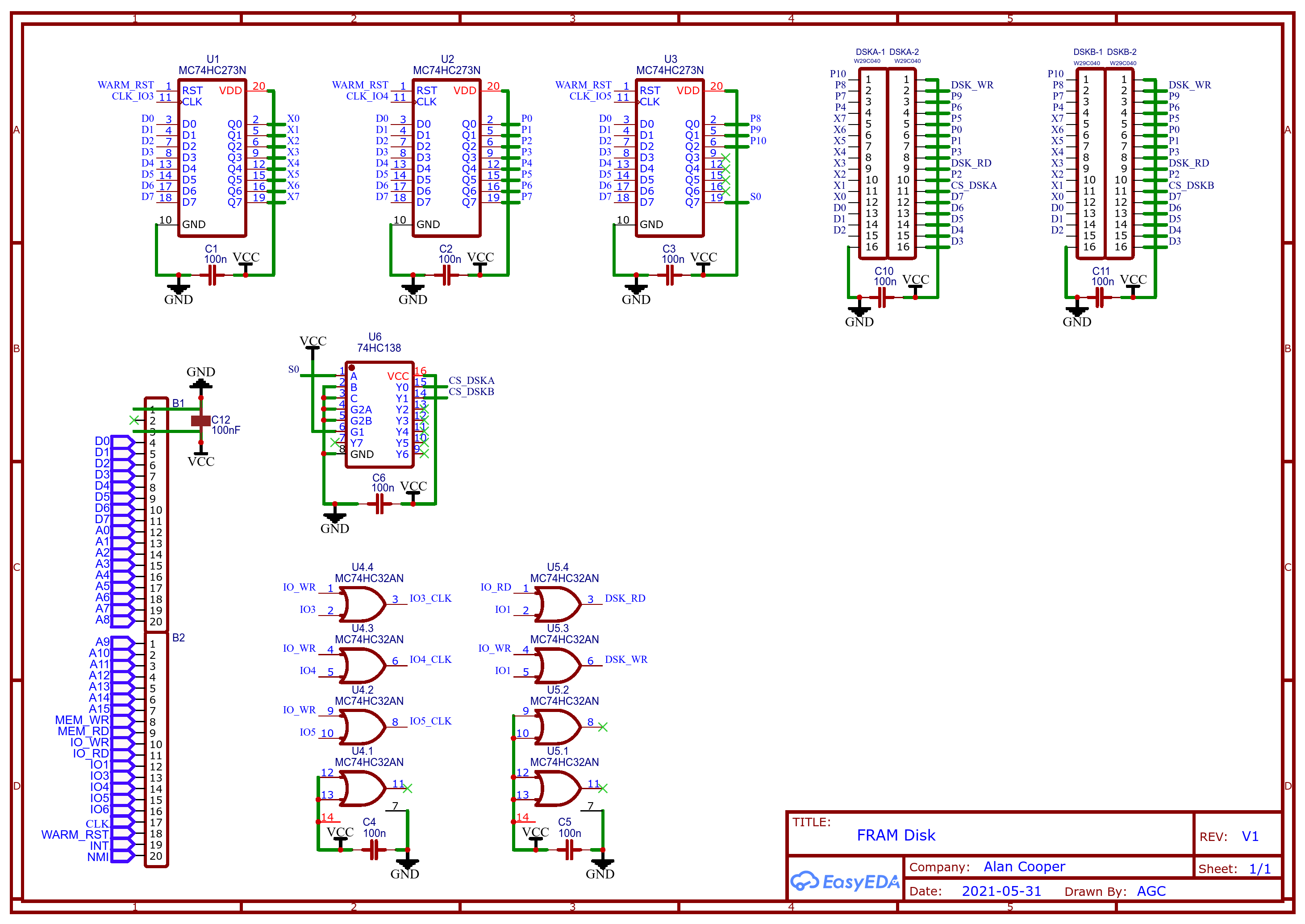
Here is a schematic two chip disk system:
![]()
Note: The W29C040 is a 512kx8 FRAM that uses a 256 bit page size.
TBC ...
AlanX
-
Modulo 6 and Finally it Works!
03/23/2021 at 00:29 • 3 commentsReducing the Serial Baud Rate
The 115200 baud for the 7.3728MHz version of the machine is just too fast.
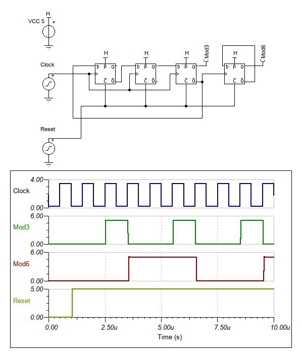
The serial clocks can be reduced by a factor of six for a 19200 baud serial rate.
Here is a schematic for a modulo 6 design that I have added to the design using 74HC74 D-Latches:
![]()
Here is an updated schematic:
![]()
Flash Drive Support
The next thing I want to do is add Flash Drive support for the W29C020 (256k x 8bit).
Updated the PCB for 19200 Baud Serial with a 7.3728 MHz Clock
Updated the Schematic and the PCB. It is sort of worth while building this version.
Adding the Flash Drive requires a bit of coding.
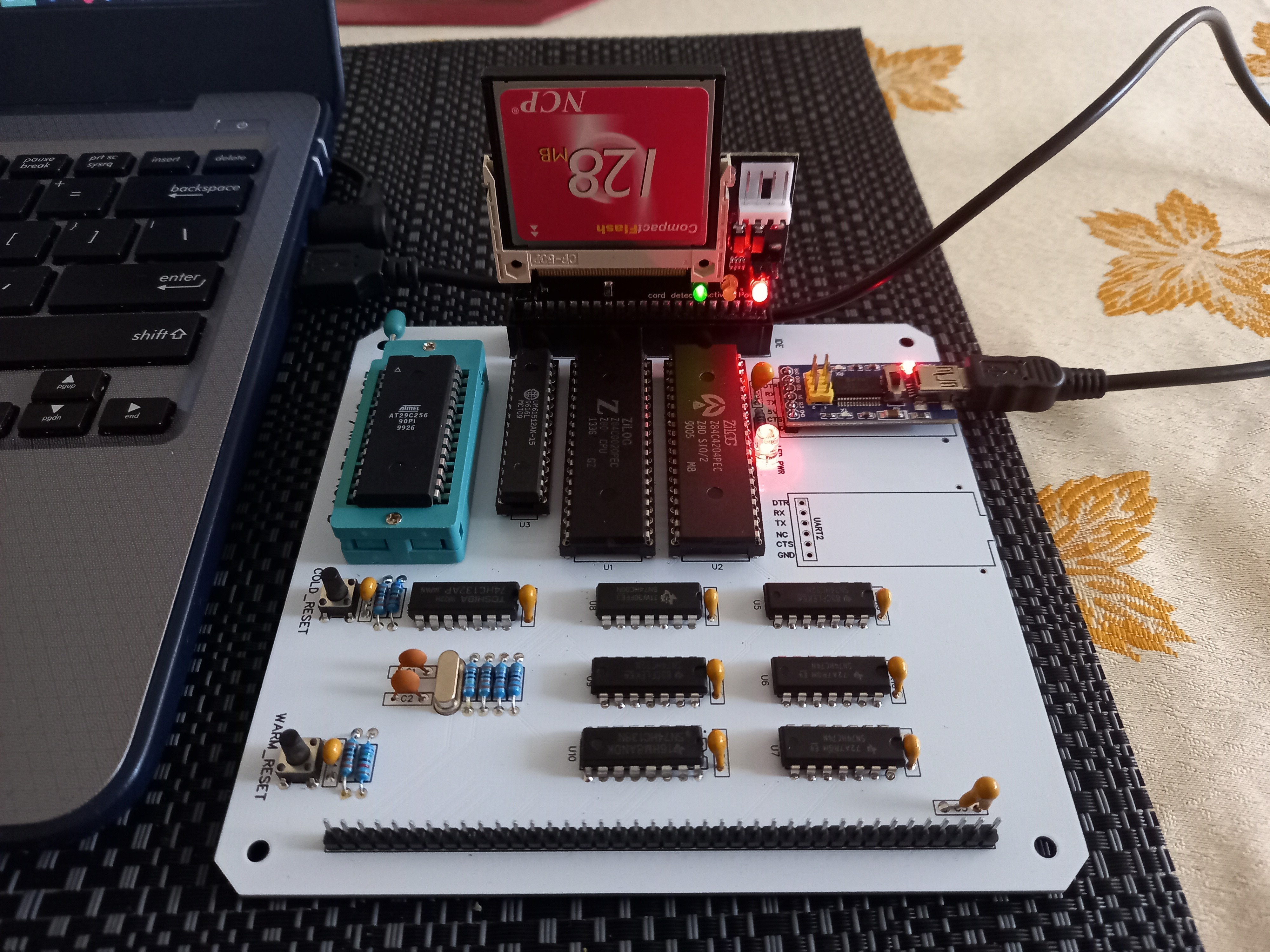
Updated PCB has Arrived
The update PCB has arrived:
![]()
Unfortunately there were two problems:
- The main clock is running but is pulled down(?)after the buffer.
- The reset circuit is dulled down.
Pulled the Z80 CPU, no change.
Pulled the Z80 SIO/2 and now the main clock and reset works.
Checking the modulo 6 circuit and it is locked up?
Check the Z80 CPU in the original board and it works.
The Z80 SIO/2 is dead. The fact that it pulled down the clock and the reset lines suggest it may be a fake chip.
Checking the modulo circuit it did work once. I think the reset rise time is too slow for the relatively fast clock. Very small differences between the two chips results in the different reset times thus locking up the circuit. I will need to redesign the reset circuit.
Minor Success
A minor success. I removed the de-bounce capacitors from the board and the modulo 6 clock divider now works. I can configure a divide by six without the reset signal by using the spare NAND gate but better to have a proper reset signals.
However the serial is still dead. The SIO/2 works with the original board if I swap it out so I must have a miss understood something about dividing down the serial clocks or there is a wiring error. I just can't find the problem.
Swapped the ROMs between boards and they are okay.
I was a bit rough re-soldering the connection pins for the USB-Serial board, may be I broke a track? No.
Okay, must be a schematic/wiring error. Yes, found it, the RAM CE is inverted. No my mistake.
New Boars Arrive
New boards ordered (with my RAM CE mistake). Assembled. Hacked the RAM CE. Clock and Modulo 6 work fine. Okay pull the modulo 6 chips and jump the serial clock. Checked the reset circuit. Back to where I was a week ago.
Spent the next day checking the schematic, no success.
Measure the signals on the old working board and compared them to the dead board.
Something wrong with IOREQ, it looks tri-state?
Isolate the problem to the Z80 CPU. Did not expect that!
Swapped it out and still not success.
Something wrong with the D0-D7, the appear pulled down but not all the time.
Starts okay and then goes down.
The only chip I have not pulled is the RAM. Something for tomorrow.
Tomorrow is Here
Swapped out the PROM and the SRAM. Same problem. Pulled the SIO/2 and yes.
I bought three of these SIO/2 and Z80 CPU from the same place. They are used chips (not new old stock). At least one dead Z80 CPU and SIO/2. One SIO/2 had broken pins. Not a good buy!
Swapped my last unused SIO/2 chip, same problem. Checked the supply voltage and that is still good. I check the good board and I have a mix of signal (i.e. 0v and 5v) and some "tri-state" (i.e. 3.4v). The databus on the Z80 does go tri-state normally so that is okay, but 3.4v tri-state seems odd on a all CMOS system.
Tri-State?
Okay, I will add a 22k pull up resistor to see it it really is "tri-state". At first it seems to be yes until I hit the reset. It seems as if I have exceeded the power supply limits from the FTDI (i.e. USB to serial converter).
Perhaps Z80 CPU is not booting up correctly. With the power supply circuit I am using a cheap no-name 10uF tantalum while on the working board I use a 22uF tantalum from my local electronics store.
There is a problem with the working board with some of the SIO/2 chips. The board will reboot a few times before stabilising. This happened with the used version of the chips.
Which is why I focused so much on these chips. But now I have a new line of exploration to follow. The (static) power supply is not up to task:
- Z80C CPU 50mA
- Z80C SIO/2 100mA
- AT29C256 50mA
- UM61512 160mA
- Total 360mA
So what does a USB 2.0 connection deliver?
Minimum (standard) 100mA and maximum (high power) 500mA!
So it should be okay but no guarantee.
I will try upgrading to power supply capacitor next. At least after our 3 day lock-down!
Updated the powers supply, still no success. This is getting very frustrating!
I will swap main components with the working board and see if this is the problem.
I can't swap out the USB to serial adapter but I really doubt the problem is here as I have tried this before.
At least I can then confirm that the main components are okay.
Then I will check the nets versus the PCB board (EasyEDA changes components from time to time so it is possible a net is missing without showing an error).
After that, I have no choice but to return to the working board design and start again.
Tracing the PCB
Okay, this morning I grabbed a spare PCB, my multi-meter, logged on to EasyEDA, printed out the schematic, and started tracing the nets on my PCB.
The first net "A0" checked out. This is going to take some time!
Jumped to "D0" and as I gazed at the schematic I saw that I had swapped D0-7 with D7-0. Bugger!
Checking the working board schematic, it was right. So I had introduced this error.
I have wasted two months over this error! But this is what happens when you get older, you just can see the bugs. Oh well.
Updated the latest board and sent if off for manufacture.
Very Annoyed with Myself
I got the updated board, installed all the components and fail!
Checked everything I could and I suspect the PROM.
It is working but the code is wrong. I just know!
I checked the schematic over and over again but I cannot see it.
Very frustrated.
I wandered over to the PCB and checked import.
Shit, I forgot to import changes before rebuilding the PCB and sending it off for fabrication.
What a waste of components.
Oh well, update the PCB and send it off again.
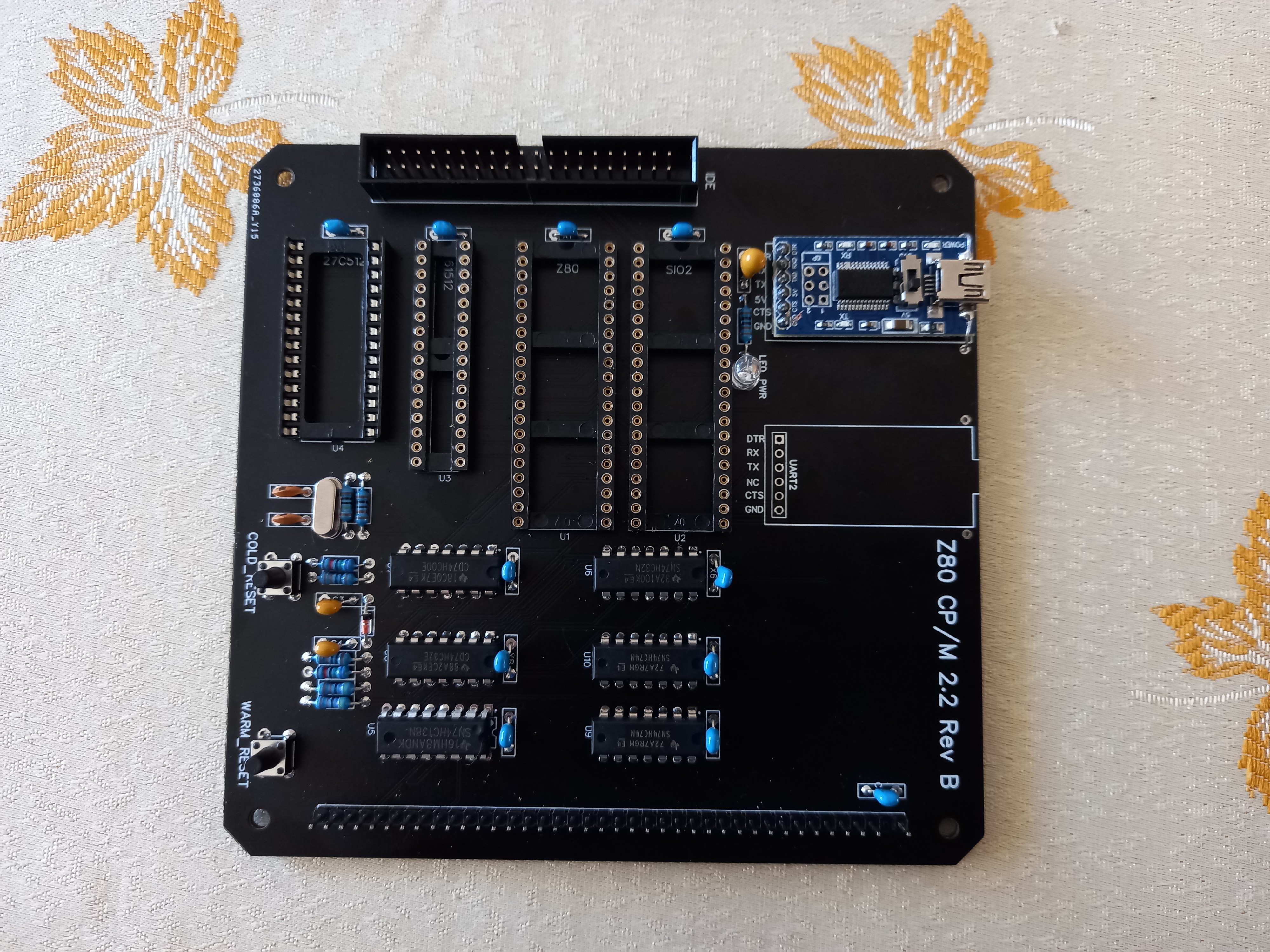
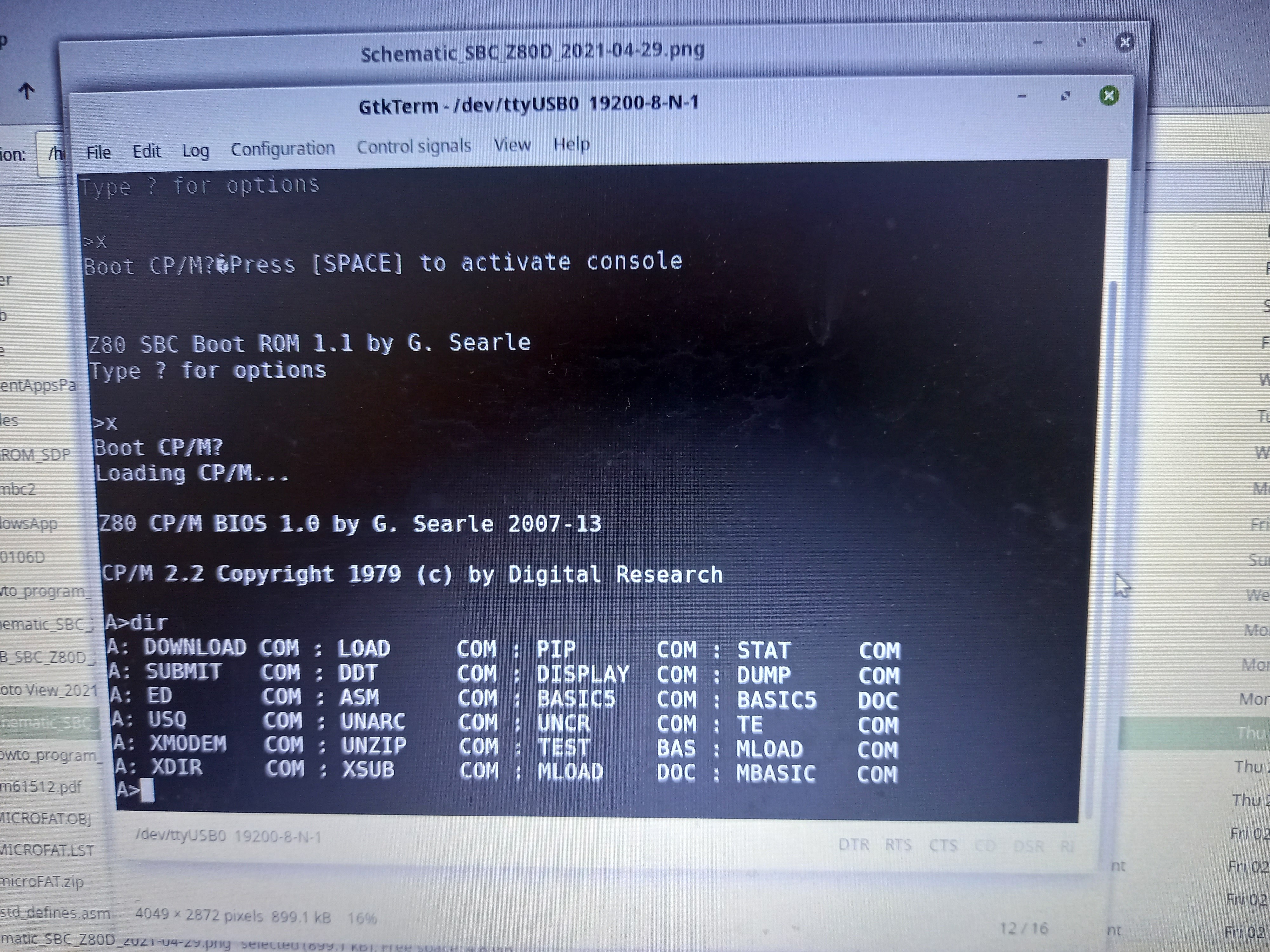
Finally it Works
Finally it works:
![]()
And it looks nice in white:
![]()
The SIO/2 is overclocked but working fine.
AlanX
-
TurboPascal and C Compiler
03/22/2021 at 12:07 • 0 commentsTurboPascal3.01a
Uploaded TurboPascal for the Z80. Installed for ANSI, worked fine with GTKTerm.
I have used TurboPascal3.02 for PC for years. I love it, but the the CP/M 80 version has no graphics. Which is one of the features I use quite a bit.
C Compiler
Uploaded the Aztec C80 v1.05b. Its probably the smallest complete package around. It has floating point but the syntax is K&R not ANSI.
I think the Hi-Tech C (Z80) compiler is near ANSI if that is essential.
Rock Solid
So far the machine has been rock solid. Works very well.
Reducing the Serial Clock
The next version of the board will divide down the serial clock by six (i.e. 9600/19200 baud). No need to run at 56700/115200 baud.
AlanX
-
Fixing Grant Searle's File Package Program
03/21/2021 at 02:17 • 0 commentsInstalling CP/M
Grant provides a CP/M file package (CPM211FilesPkg.txt) that can be uploaded using GTKTerm and "DOWNLOAD.COM". So getting CP/M working was easy.
Installing Custom Packages
Grant provides a MS Windows program called FilePackage.exe that can creates a custom HEX file packages that work with DOWNLOAD. Unfortunately, it does not work under Wine (Linux). Even on a Windows PC it does not work unless you register COMDLG32.OCX. To register COMDLG32.OCX:
1) Copy the file to c:\Windows\SysWOW64\comdlg32.ocx (for Windows 64 bit system)
2) Open a command window and run "regsvr32 c:\Windows\SysWOW64\comdlg32.ocx"
For a 32 bit windows system substitute "SysWOW64" for "system32".
File Package Bug
File Package (and DOWNLOAD) have a bug in that they don't mark the end of the file. This is important for text files. Without the "end of file" (EOF) marker (^Z or 0x1a), the text file repeats part of the tail of the file. Not fatal but messy. You could patch DOWNLOAD (as the source is provide) to insert an EOFmarker but in my case I wrote a short C command line program (file2hex.c). It only converts one file at a time but you can archive the files first. I have uploaded USQ, UNARC, UNCR and UNZIP. The special i8080 UNZIP.COM version only works unzip.exe version 1.11 (yes it still can be found on the Internet).
If you are having problem uploading files, providing you have PIP and LOAD installed, then you can upload an iHEX8 file using:
1) A:PIP FILENAME.HEX=CON:
2) "Send RAW file" (FILENAME.HEX) in GTKTerm.
3) ^D to get the prompt back
4) A:LOAD FILENAME.HEX
Here is file2hex.c:
#include <stdio.h>
#include <string.h>
#include <stdlib.h>

int next(FILE *,char *);
int main(int argc,char **argv) {
  int user;
  char to[14];
  char from[14];
  int ch,len,sum;
  FILE *fp1,*fp2;

  if (argc!=4) {
    printf("usage: ./file2hex.run usernumber filename.ext filename.hex\n");
  } else {
    strcpy(from,argv[2]);
    if ((fp1=fopen(from,"rb"))==NULL) {
      printf("file2hex: Source file %s not found\n", from);
    } else {
      strcpy(to,argv[3]);
      if ((fp2=fopen(to,"w"))==NULL) {
        printf("file2hex: Could not create destination file %s\n", to);
      } else {
        user=atoi(argv[1]);
        // fseek(fp1,0L,SEEK_END);
        // len=(char)ftell(fp1);
        // fseek(fp1,0L,SEEK_SET);
        sum=0;
        len=0;
        fprintf(fp2,"A:DOWNLOAD %s\r\n",from);
        fprintf(fp2,"U%d\r\n",user);
        fprintf(fp2,":");
        while ((ch=fgetc(fp1))!=EOF) {
          fprintf(fp2,"%02X",ch&0xff);
          sum+=ch;
          len++;
        }
        // Insert EOF  Marker if not end of record
        if (len%128!=0) {
          fprintf(fp2,"%02X",0x1a);
          sum+=0x1a;
          len++;
        }
        fprintf(fp2,">%02X%02X\r\n\r\n",len&0xff,sum&0xff);
        fclose(fp1);
        fclose(fp2);
      }
    }
  }
  return 0;
}
AlanX
-
EasyEDA - The Schematic and PCB
03/19/2021 at 02:03 • 0 commentsThe Schematic and PCB
I use EasyEDA for the Schematic and PCD design and manufacture.
This is a well known project and there are a number of schematics and PCBs that can be used on the web-site.
I used https://easyeda.com/twahl/SBC_Z80_REV2 as a base for my schematic and PCB.
In my case I made a few changes, first I removed the MAX232 as I will use a FT232 USB TTL serial interface card. And the power supply as I can draw the 5v power supply from the USB connection.
I reworked the Cold Boot and Warm Boot to include a 50ms debounce RC network. It is a puzzle to me that not debouncing the reset buttons does not cause a problem.
I also added access to NMI and the decoded I/O addresses. But I have not added an expansion bus (to do).
I did make a few errors with the PCB:
1 Incorrect labelling of the serial port pins.
2 Incorrect switch foot-print (did not check).
3 Incorrect diode silk screen (backwards?).
4 Finally I had a problem finding an 90 degree IDE socket that bends with the CF facing up. So I used a straight IDE socket.
Burning the ROM
In my case I used an AT29C256 Flash ROM. I have a number of these and a programmer for them.
Power Up
Because of the incorrect reset button footprints the reset signal was locked down. An easy find an fix.
Communicating with the Machine
The boot up was fine, Basic works, but I was unable to upload hex files.
At first I suspected that the overclocked SIO/2 was tripping up. So I replaced the 7.3728 MHz crystal with a 3.6864 MHz crystal. It still did not work.
I use Linux and was using Putty to communicate with the machine. I needed to introduce a delay after each character to give the machine time to process the serial communications. I know HyperTerm does this but I don't have this for Linux. I found GTKTerm that has an option to introduce delays after each line. It worked well.
AlanX
Grant Searle's Z80 CP/M Design
I thought I would put this CP/M 2.2 Z80 project together. See what I can learn.