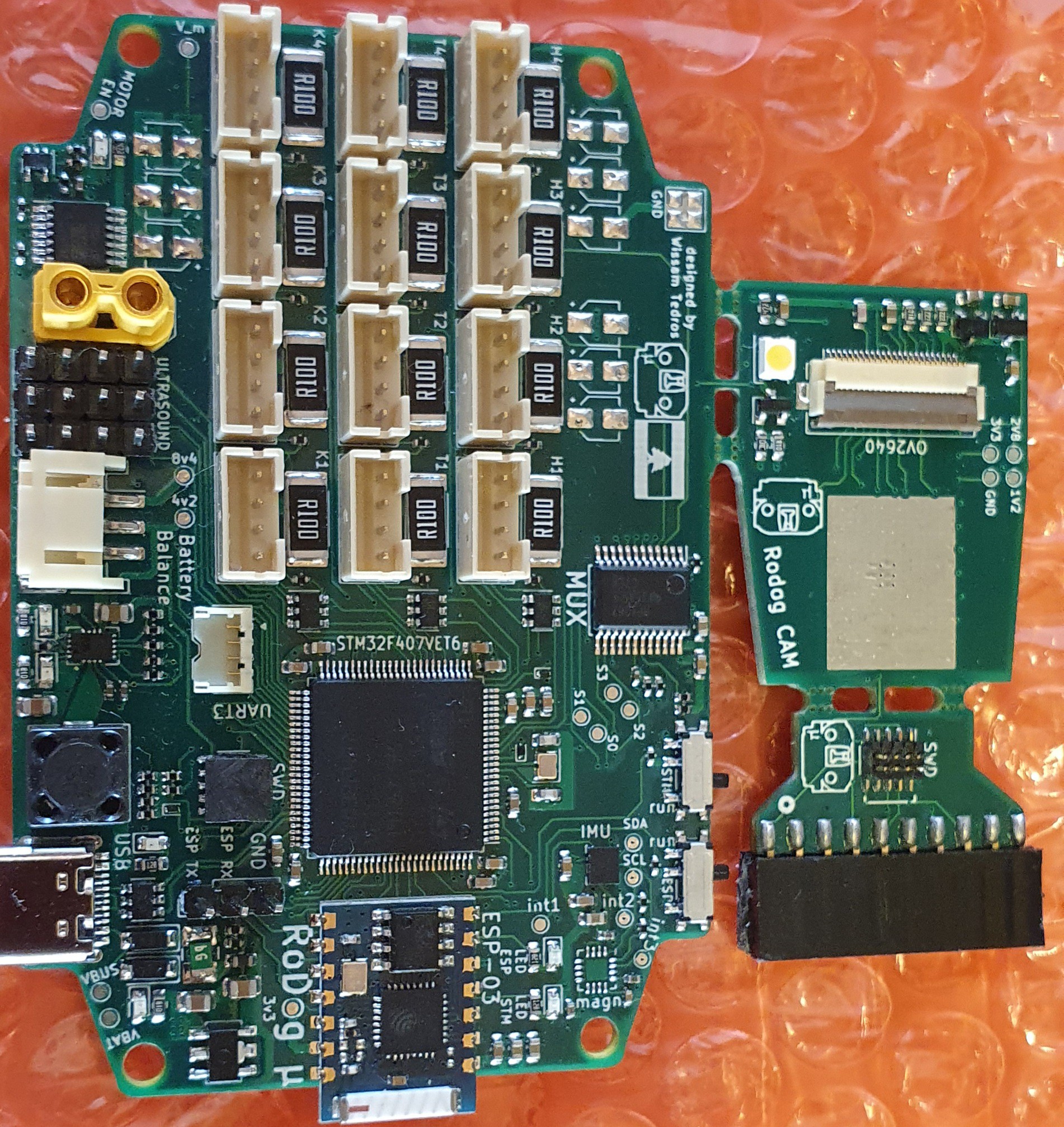
It features: (* New)
- *STM32f407vet6 rather than the STM32f405rgt6.
- 12 PWM outputs for the servos
- 12 ADC inputs for position feedback
- 12 current sensing circuits for force estimation feedback
- *lsm6dso32x and hmc5883cl magnetometer working as a 9DOF Inertial measurement unit with interrupt pins attached to the MCU.
- *On-board Esp8266 for AT commands, and UART port exposed for programming it
- *Load switch on the Servo Power, this Load switch is activated by a GPIO and the MCU Reset pin, if the MCU is in Reset mode, the power to the servos is cut-off, this is to remove the random chaotic servo moves when the microcontroller is in reset mode.
- *New IC for battery management, (Charge through USB-C, and Balancing)
- *DCMI interface and a ov2640 camera breakout
- *SD card with SDIO interface
- *3 Ultra-sound sensors GPIOs with connected Trigger pins
- *UART port exposed for any expansions needed
- *Better current consumption (9~25mA vs previously 20~50mA)
- *All ADC inputs are protected with clamping Diodes and resistors.
- *Better Isolation between the Power planes and the I/Os
- *lots of indicator LEDs and Test-Pads(check the layout + Schematics)

As you can see, there are 3 boards, the Mother board, the camera breakout , and an ST-LINKV2 to mini SWD breakout, of course, they are meant to be separated
you can Check the schematic and GRBR files in the project files section!
 Wissam Tedros
Discussions
Become a Hackaday.io Member
Create an account to leave a comment. Already have an account? Log In.