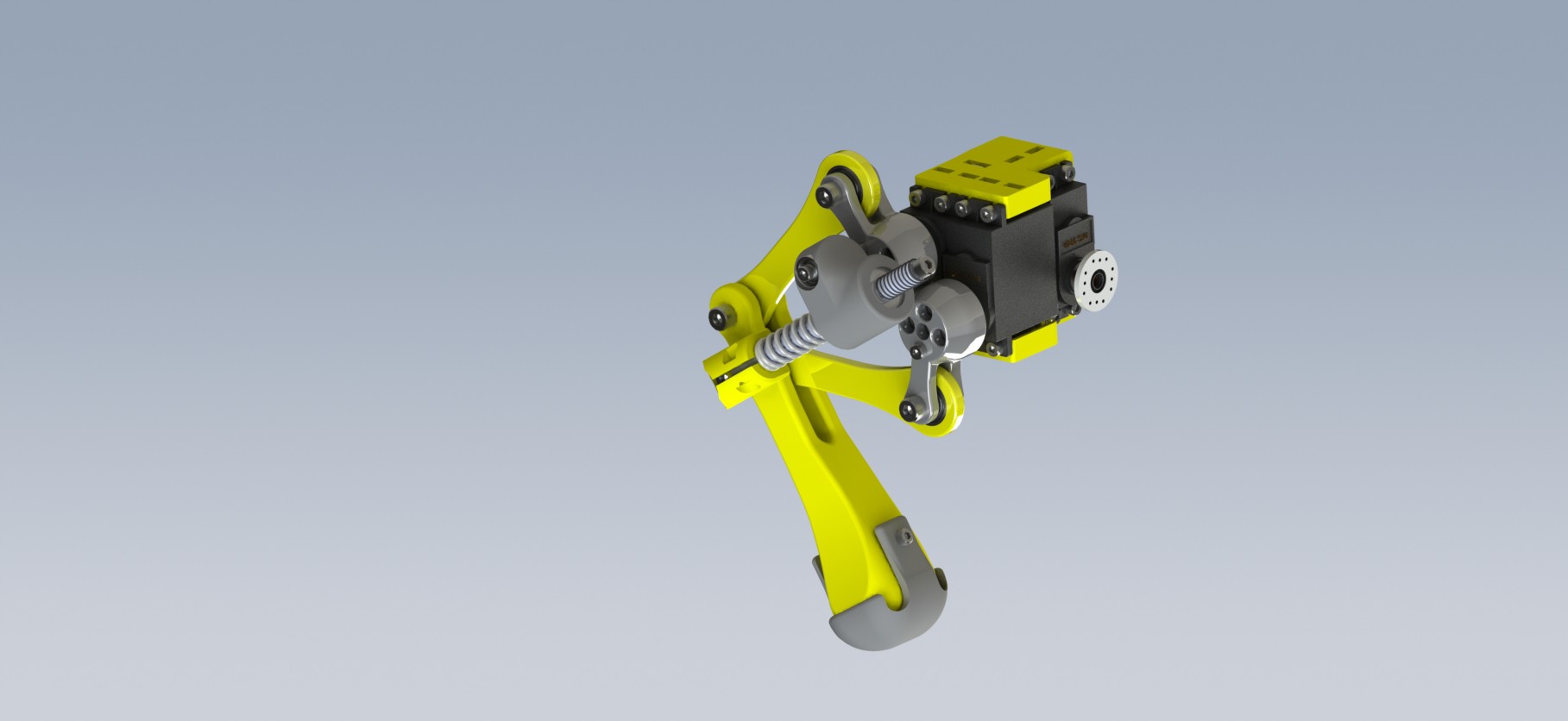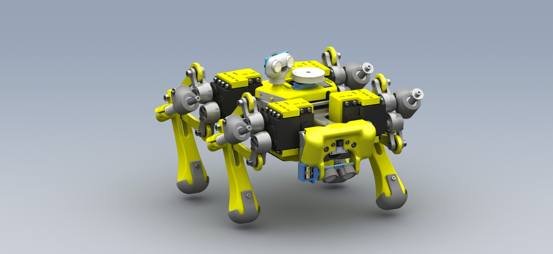
for version 2 , I used a teensy 3.5 and a raspberry Pi 3A+, connected together on a breakout PCB that I milled on a hobby CNC engraver, the teensy was a good deal between performance and accessibility, but I knew that I had to design my own board someday for a better performance. Version 2 was a really good example of CAD != reality, this project being my first major one, I just thought that by perfectly defining all my constraints in CAD and fully defining an assembly, I would achieve a perfect fit, a smooth as silk mechanism, and rigid bodies that absolutely won't twist, bend, or even crack under load, especially 3D printed parts, lets just say that I did not completely know what I was doing, just having fun in CAD. The design was not terrible, it just didn't match my expectations, it is important to note that I don't really have a lot of experience in CAD, I taught myself how to use SolidWorks.
my Leg mechanism was a constrained 4 DOF manipulator, a very stiff spring sets a constraint length between the end effector leg link and one of the cranks attached to the motor, the idea was to let the spring absorb any sort of load on the robot. As stated in a previous log, I actually swapped replaced this weird mechanism, and replaced it with a normal leg mechanism, where the joint are just connected serially, each motor on a joint instead of parallel control, I achieved with that design my first static movements, (pitch roll yaw, and XYZ body translations) with an inverse kinematic model.


 Wissam Tedros
Discussions
Become a Hackaday.io Member
Create an account to leave a comment. Already have an account? Log In.