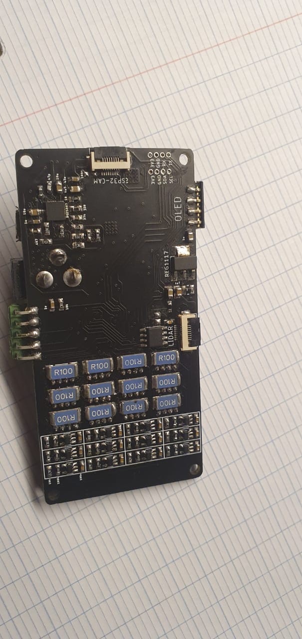
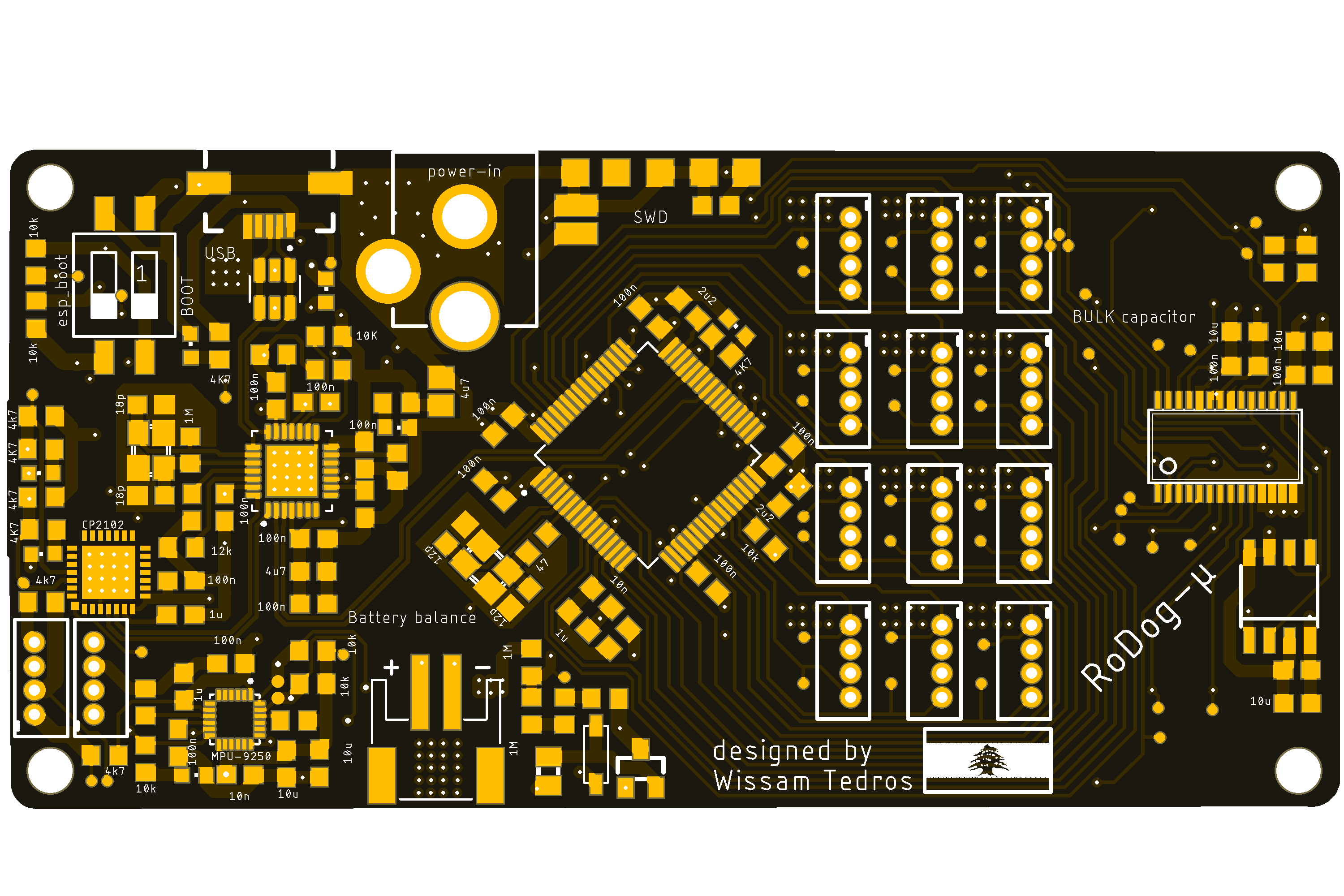
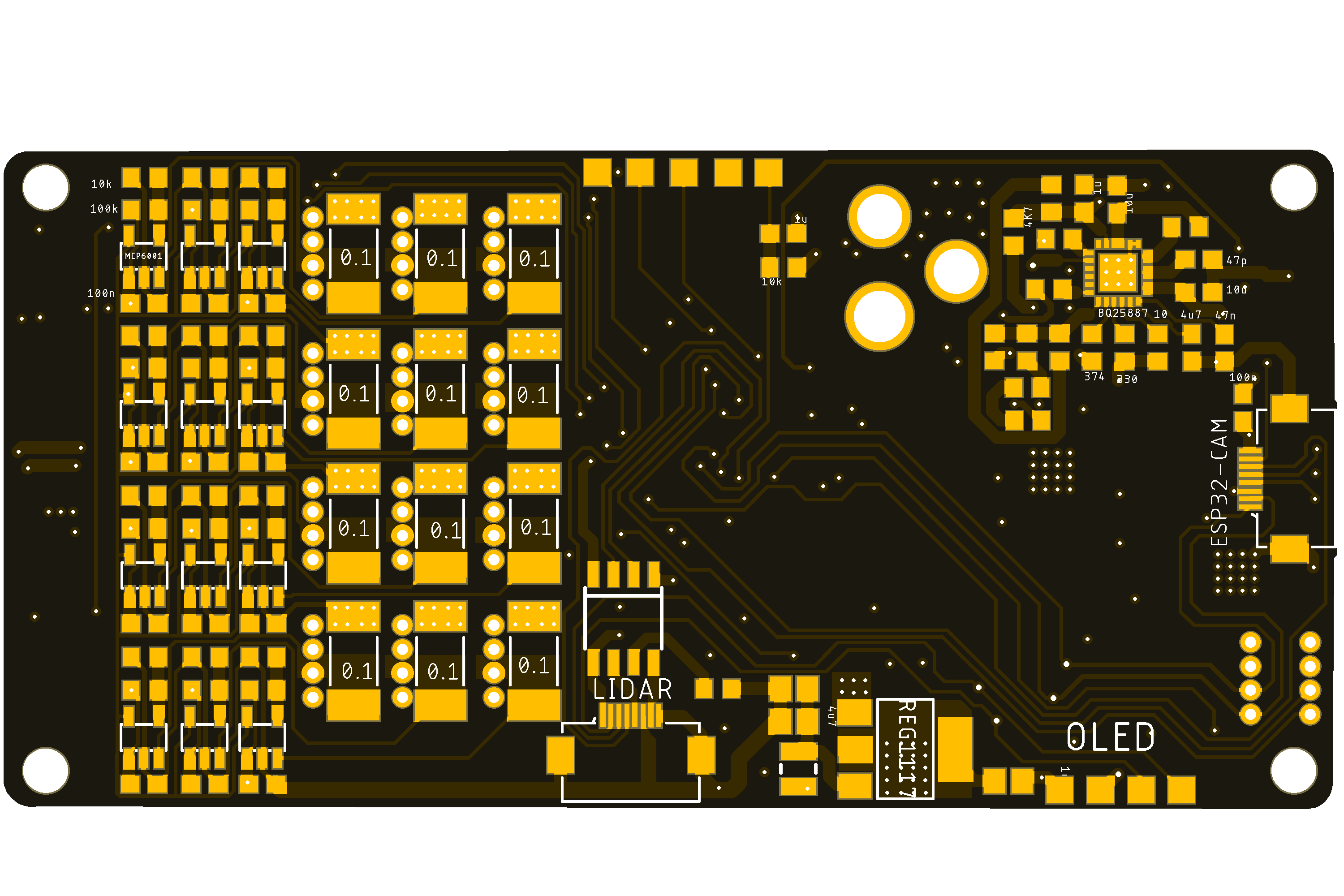
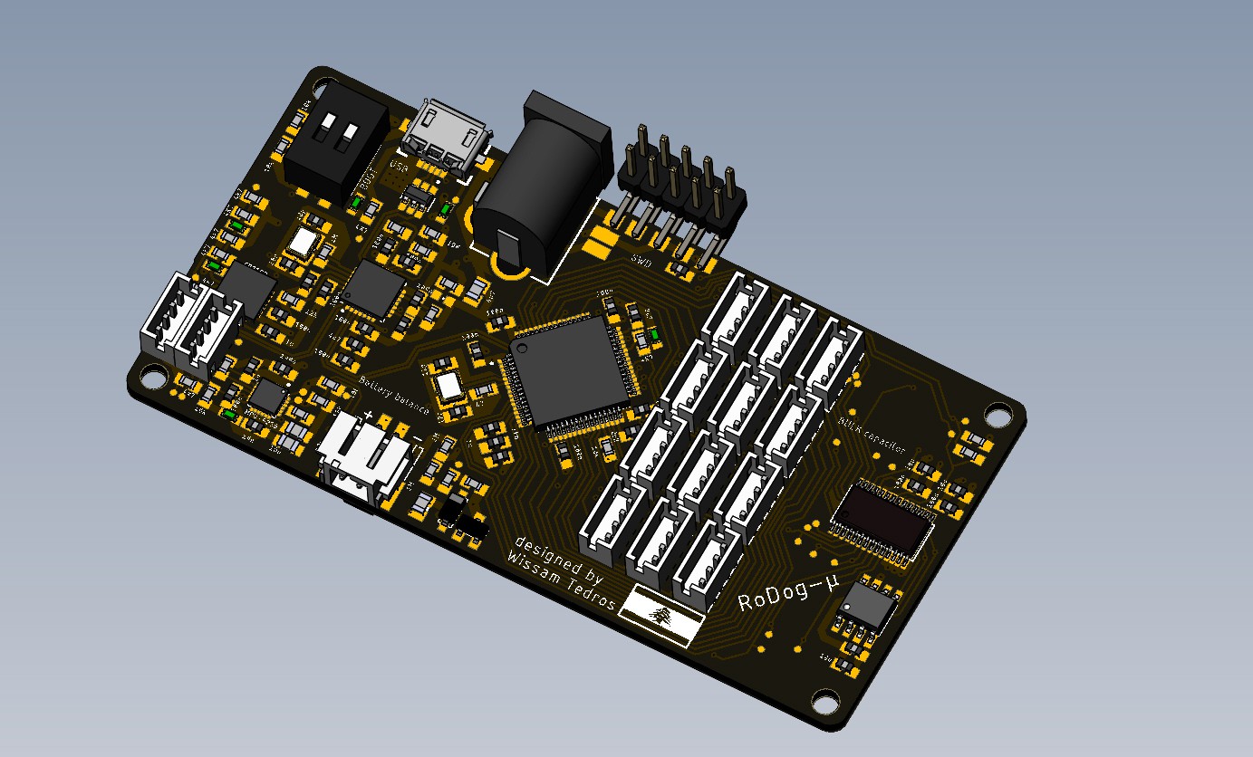
I finally Got time to assemble my PCB for the robot, 4 layers, controlled by an STM32f405RGT6,
it features:
- 12 PWM outputs for controlling RC servos
- 12 ADC position feedback, from the Servos' potentiometer
- 12 Shunt resistors of 0.1ohms, for current feedback, this signal is then amplified with a non-inverting op-amp circuit to a good readable range, 0~2.7V, an AD7490 handles the reading and is connected to the MCU by an SPI bus
- 9DOF (accelerometer , gyroscope , magnetometer) inertial measurement unit MPU9250 connected to the MCU by I2c
- small FPC connectors(for future plans), I have a plan to make a small 360 scanner, using a hard disk DC motor, so I also added an H-bridge for that, and some GPIOS.
- BQ5887 for 2S Li-ion/Li-Po batteries charging and balancing, to charge the robot from the USB port
- USB-Hub for STM32 output and cp2102 USB to UART bridge to program the ESP32-camera
- 4mb external flash memory
- additional UART/I2c breakouts and an optional port for a small OLED display
- USB B-micro for charging/ and differential pair connected to the MCU
- SWD interface for the STM32


I have turned on the board, computer sees it, and the ST-LINK recognizes it, we're looking Good!

 Wissam Tedros
Discussions
Become a Hackaday.io Member
Create an account to leave a comment. Already have an account? Log In.