Close
0%
0%

Quad-ROS-bot

Development platform for agricultural robots

Public Chat
Similar projects worth following
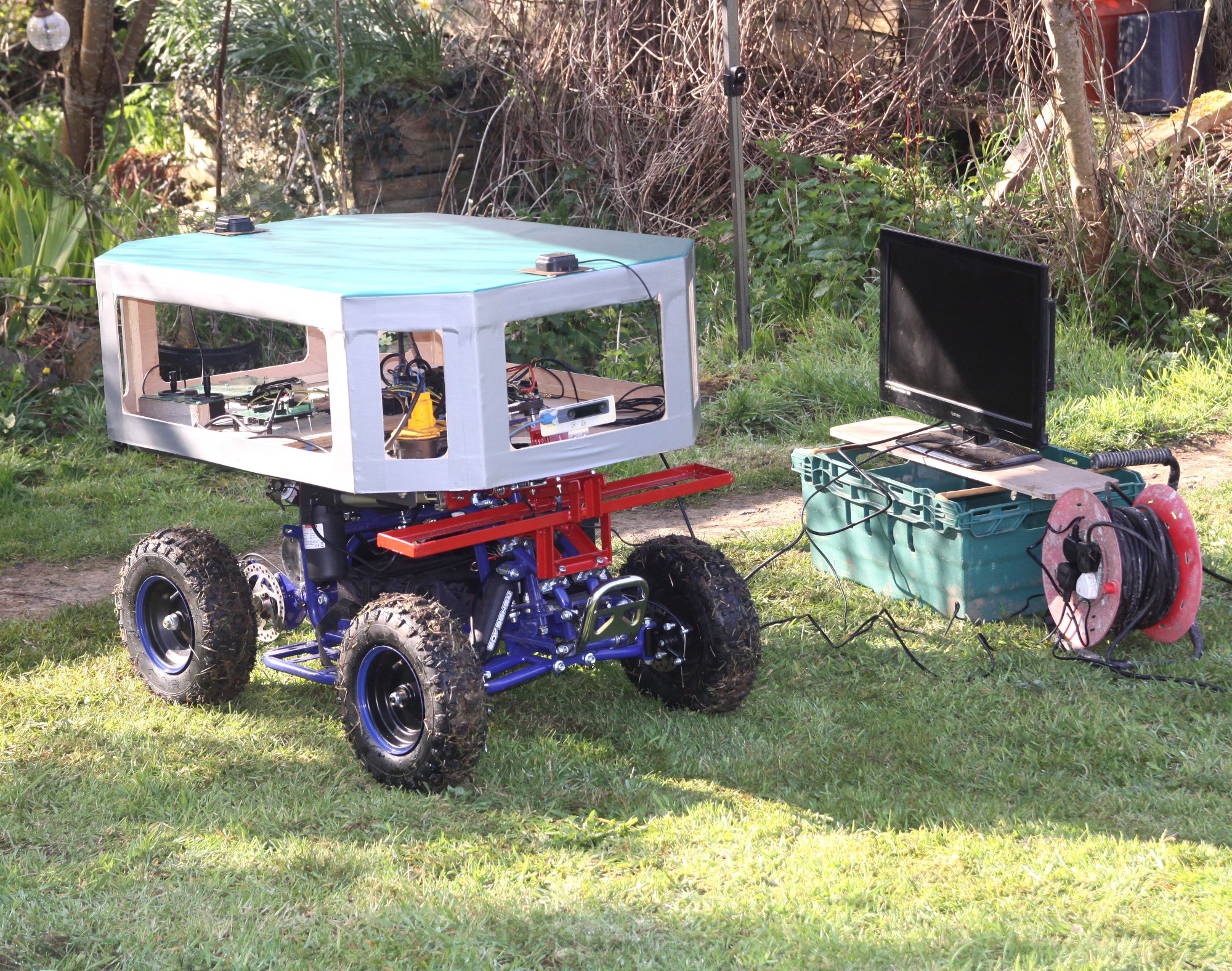
A small electric quad bike modified to navigate autonomously around a farm. We needed something small and light-weight, but big enough to carry a whole load of computer equipment and sensors to rapid prototype autonomous navigation and obstacle avoidance using the Robot Operating System (ROS). We are going to try and present a series of videos detailing the steps we take, which will be updated every 2 weeks or so. There will also be drawings for the parts made for adapting the Quad bike. Watch this space for updates !!!

If anybody wants to support any of our projects, check out our Amazon Wishlist here: https://www.amazon.co.uk/hz/wishlist/ls/3AW6R7V5BVU3R?ref_=wl_share

Patreon donations can be made here: patreon.com/Goat_Industries

After building the WEEDINATOR agricultural robot, we chose to take a small step backwards and look more closely at the more fundamental stuff like 'how is the robot going to communicate with our control center when in the middle of a large farm with no 4G reception'. We're pretty sure that we are going to need a combination of different technologies to get low latency video and data swirling around the farm. 4G, satellite and WIFI mesh will be part of the solution and the Quad-ROS-bot may well be the perfect beast for transporting the necessary radio equipment around the farm to provide a flexible communication network for larger, more specialised machines.

There's also quite a lot of work to be done with safety features to prevent agricultural robots bumping into other machines, buildings and animals. One of the detectors will be an in-house designed radar system which can be positioned around the machine to detect obstacles when going forwards, backwards and at full turning locks in both forwards and backwards, which adds up to at least 6 static sensors.

  • 1 × 'Renegade LT100E' electric 36v quad bike
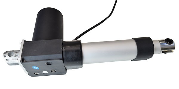
  • 1 × Gimson Robotics GLA4000-S 12V DC Linear Actuator
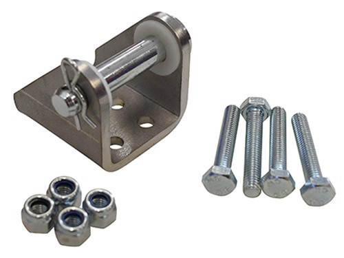
  • 2 × Heavy Duty Stainless Steel Actuator Bracket, 10mm Pin
  • 2 × TE Connectivity, 12V dc Coil Non-Latching Relay DPDT, 30A Switching Current Flange Mount, 2 Pole

  • First Autonomous Test

    Capt. Flatus O'Flaherty ☠07/07/2021 at 07:40 0 comments

    The QuadROSbot is now autonomous!

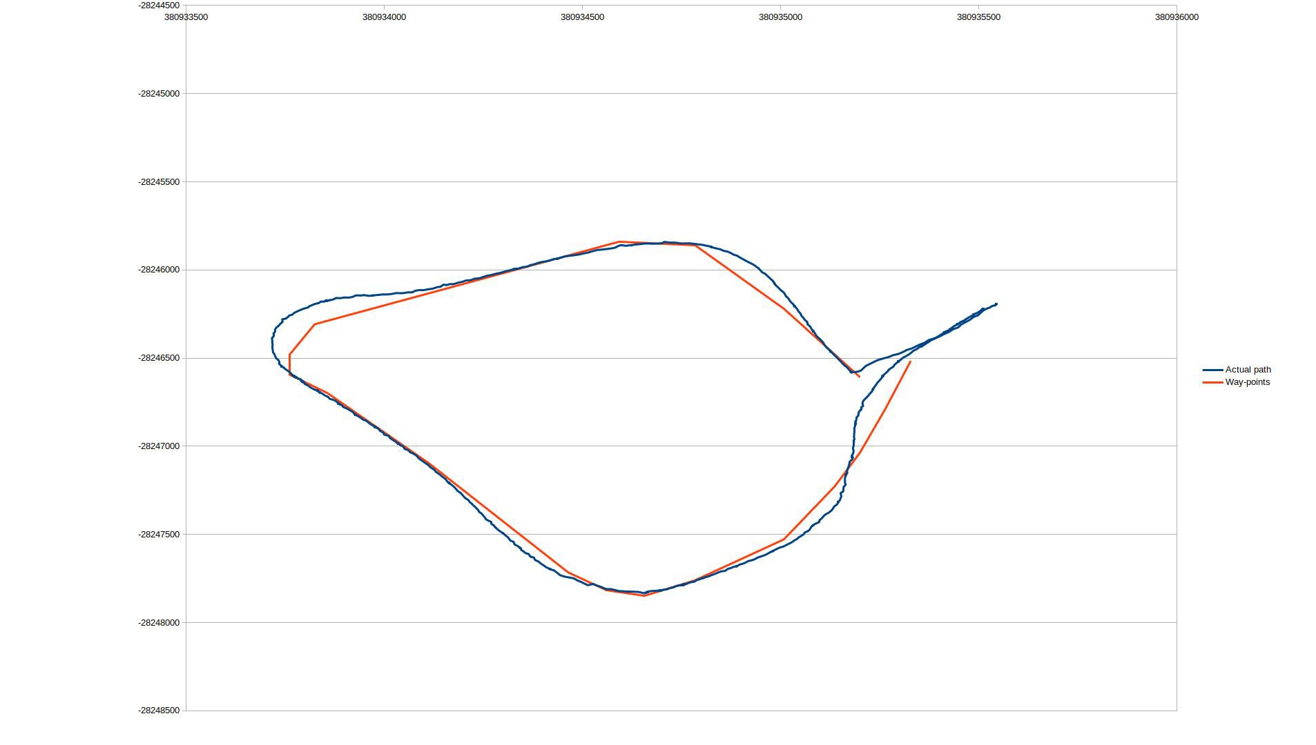
    The image below shows the original waypoints in red and the actual path taken in blue. The throttle was controlled manually, but the steering was automatic and, as can be seen, the robot followed the way-points fairly well:


    There's a noticeable over-shoot in the top left corner which can hopefully be corrected with a bit of fine tuning.

  • Robot Communication Tower

    Capt. Flatus O'Flaherty ☠05/05/2021 at 09:35 0 comments

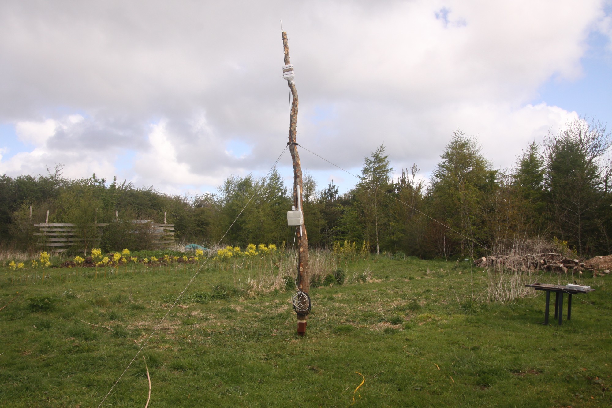
    The tower features a Multitech IP67 base station with onboard 4G, WiFi and 8 channels of Lorawan, all mounted on a home grown piece of larch harvested from our own woodland. The plan is to use 2.4 and 5 GHz WIFI to communicate with the robot, live streaming data and video feeds to the control room. The Multitech box itself will be hard wired with ethernet cable to the control room.

  • Testing navigation system - data harvesting

    Capt. Flatus O'Flaherty ☠04/17/2021 at 09:25 2 comments

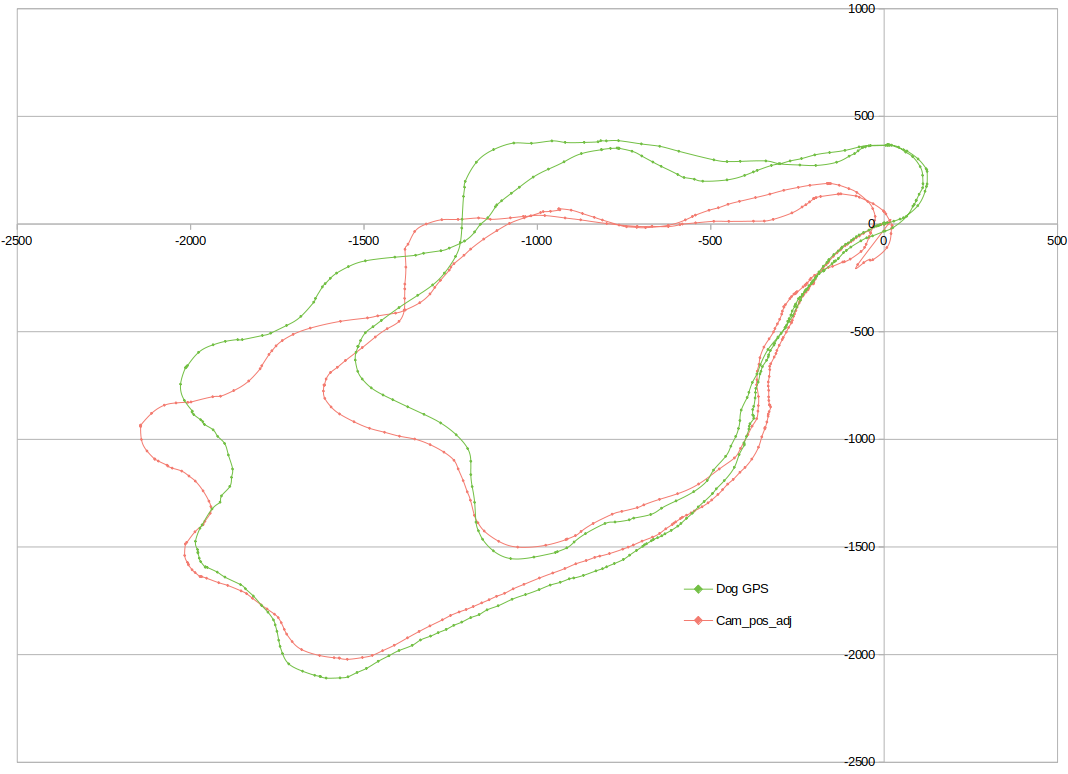
    The robot was driven 2 different laps around some fields with the GPS and T265 camera data being recorded to a CSV file. We use animal terminology for all parts of the robot and the main 'thing' is called 'dog'. It also has a snout, eyes and even a lair, or 'nest'. All will be explained later !!!

    Another rest run using a different route:

View all 3 project logs

  • 1
    Overview of the 'Renegade LT100E' quad bike

    On delivery of the quad bike, we took off all the plastic panels, inserted the main fuse and tested the motor with the bike up on wooden blocks. Video 1 shows the main features and build quality of the bike and we also hacked into the throttle connector with a 5v arduino uno to test what the signal to the motor controller should look like. The signal was the 'analog out' type, which is a high frequency PWM that 'attempt' to replicate a true voltage out. We successfully ramped the motor steadily up and down. NB. The green wire on the throttle connector is for the signal.

    Here's the code to ramp up the motor:

     void setup() 
    {
      pinMode(11, OUTPUT);
      pinMode(13, OUTPUT);
      // Serial.begin(9600);
    }
    
    void loop() 
    {
        for (int speed = 0; speed < 155; speed++) 
        {
          analogWrite(11, speed);
          delay(20);
          // Serial.println(speed);
          digitalWrite(13,HIGH);
        }
        for (int speed = 155; speed >= 0; speed--) {
          analogWrite(11, speed);
          delay(20);
          // Serial.println(speed);
          digitalWrite(13,LOW);
        }
        // pause between LEDs:
        delay(100);
    }
  • 2
    Steering actuation

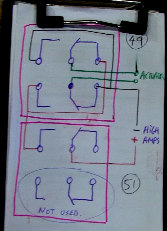
    The installation of the steering actuator is shown below, it's a thumping great 4000 N device capable of tearing the whole machine apart if not careful. The actuator needs to be able to turn slightly at each end and so is mounted on the stainless steel brackets to enable this. Also, the actuator must operate at exactly 90 degrees to the steering column or else there will be unwanted twist in the actuator as it move in and out that could damage the mounts at the ends. The actuator requires a high ampage, 12 volt supply and can be control via mechanical relays or MOSFETs. MOSFETS are much more expensive but more reliable and can be controlled directly from a micro-processor such as an Arduino, whilst the relays require an intermediator y chip, the L293E, to boost the power supply for the coils.

    This little beast is the Gimson Robotics GLA4000-S 12V DC Linear Actuator. It boasts a massive 4000 N of force, which is enough to pull the whole robot to pieces ! The actuator requires 2 stainless brackets for attaching to the robot frame:

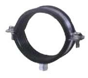
    Some heavy duty 3/8" pipe clips were used to attach to the frame:

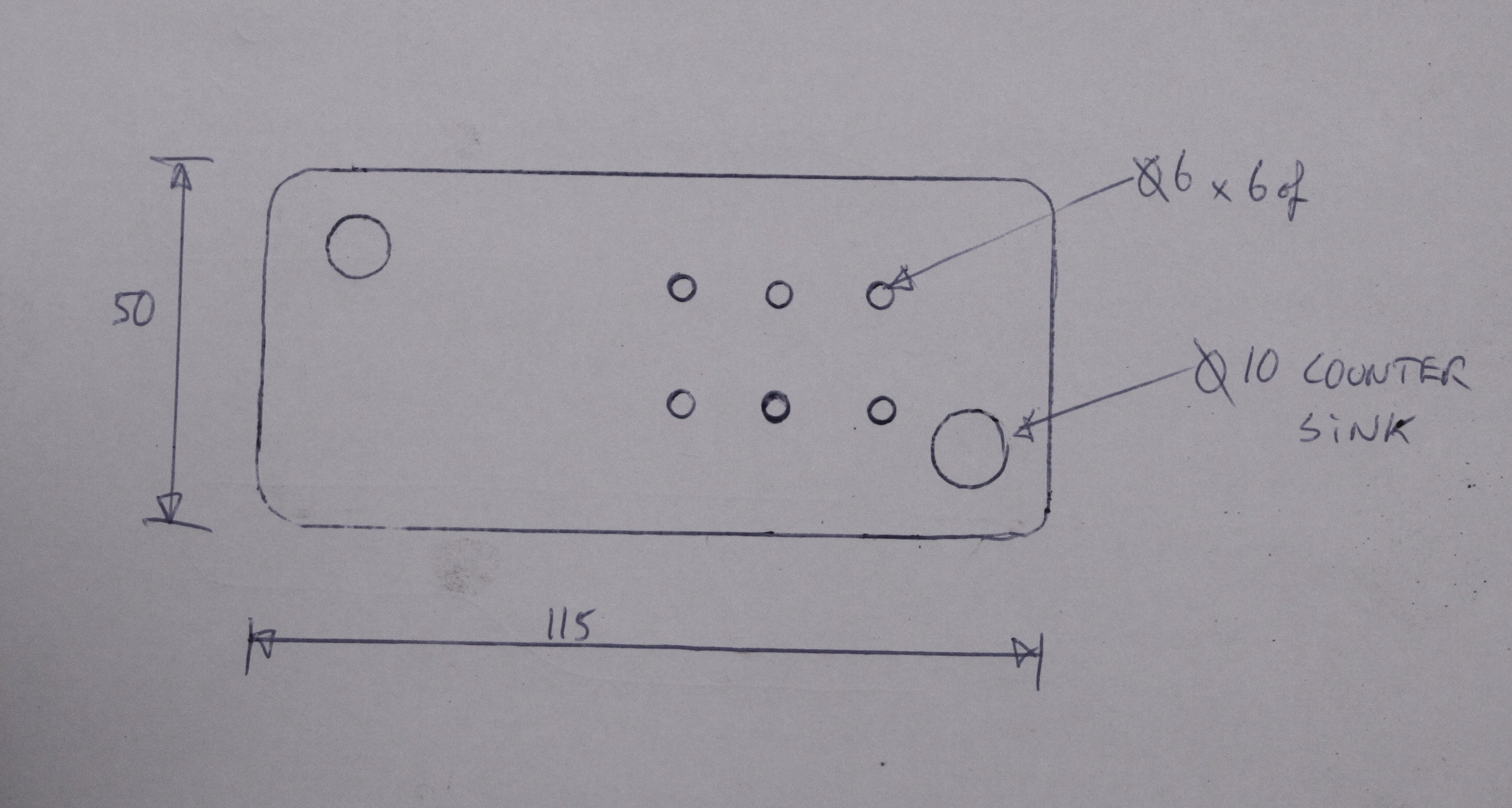
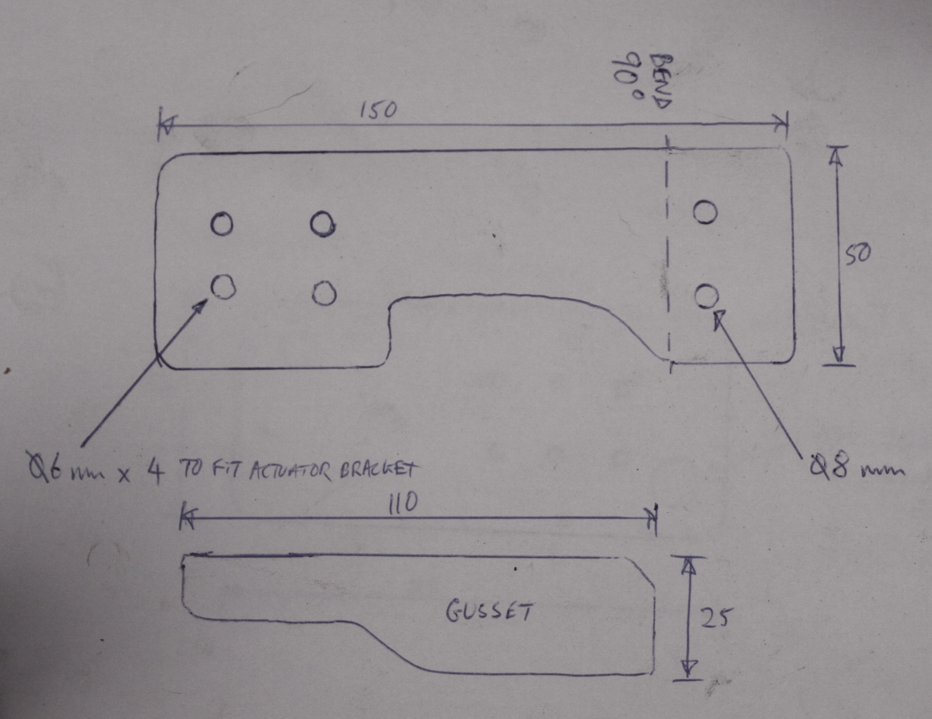
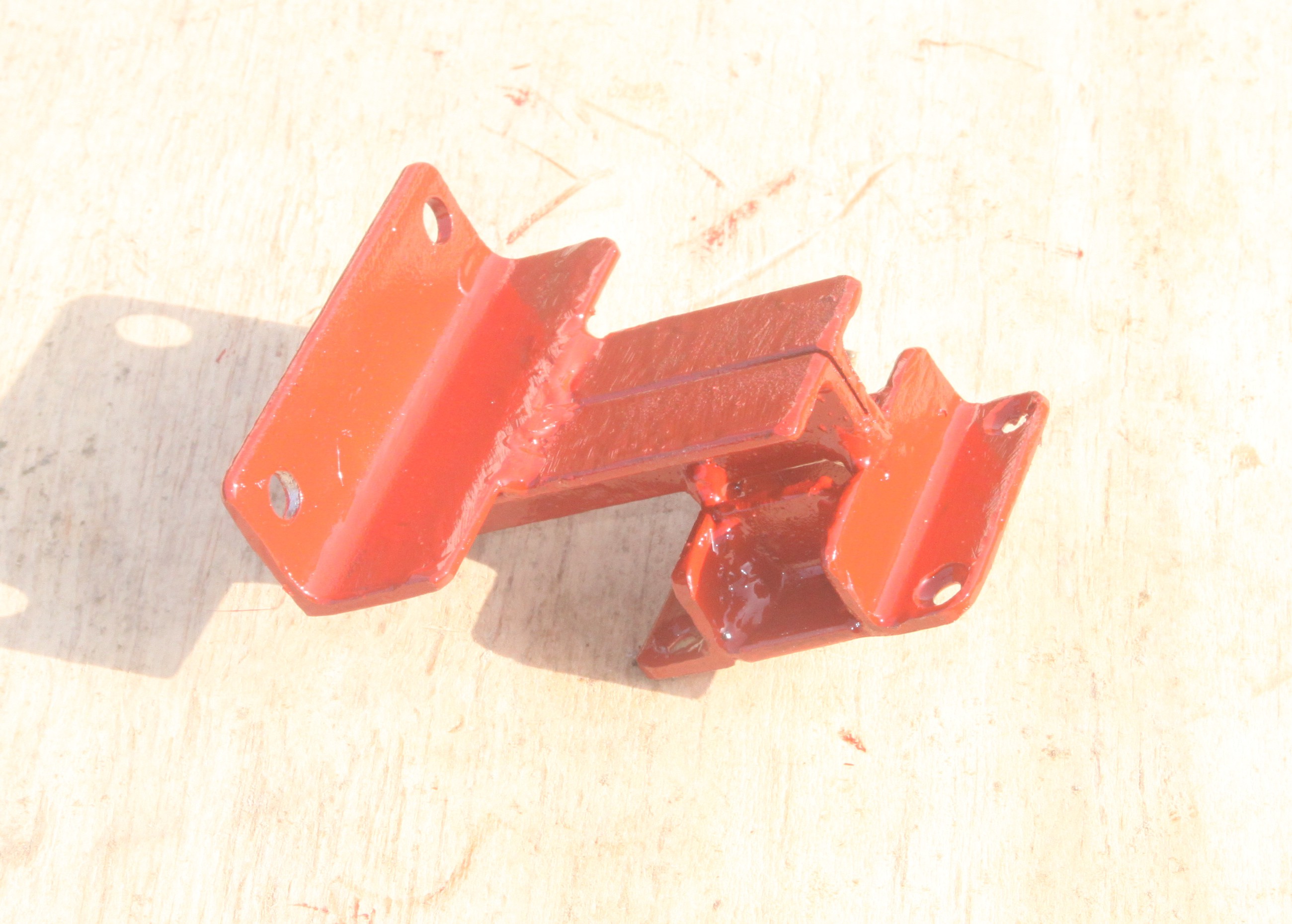
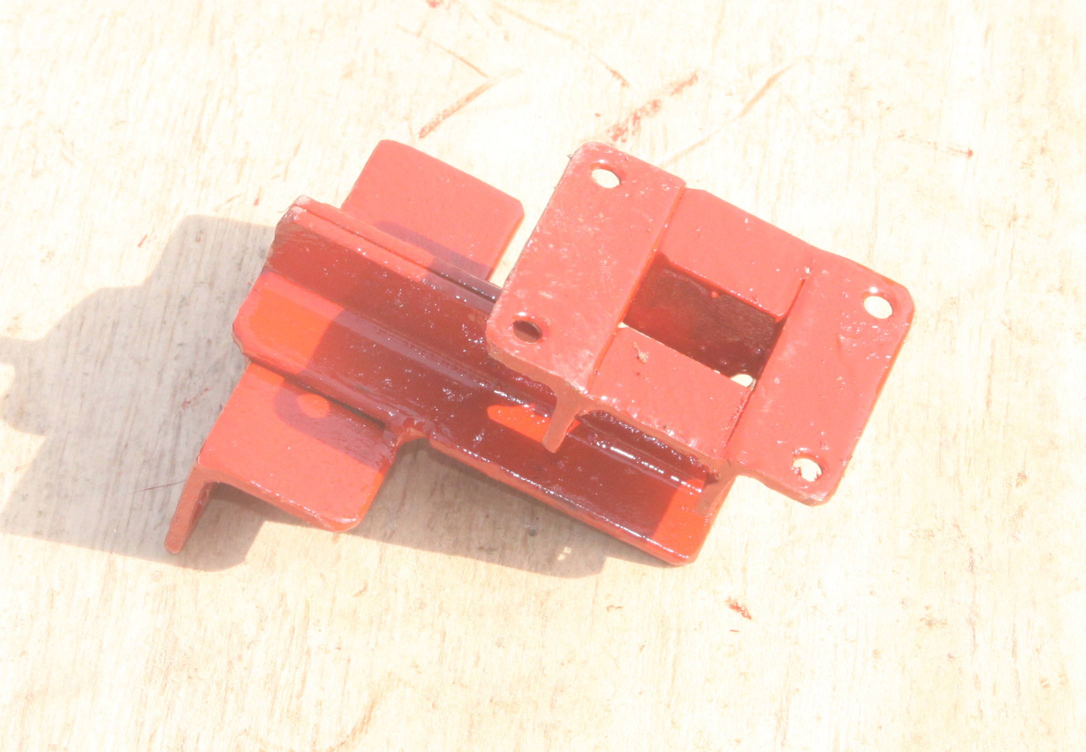
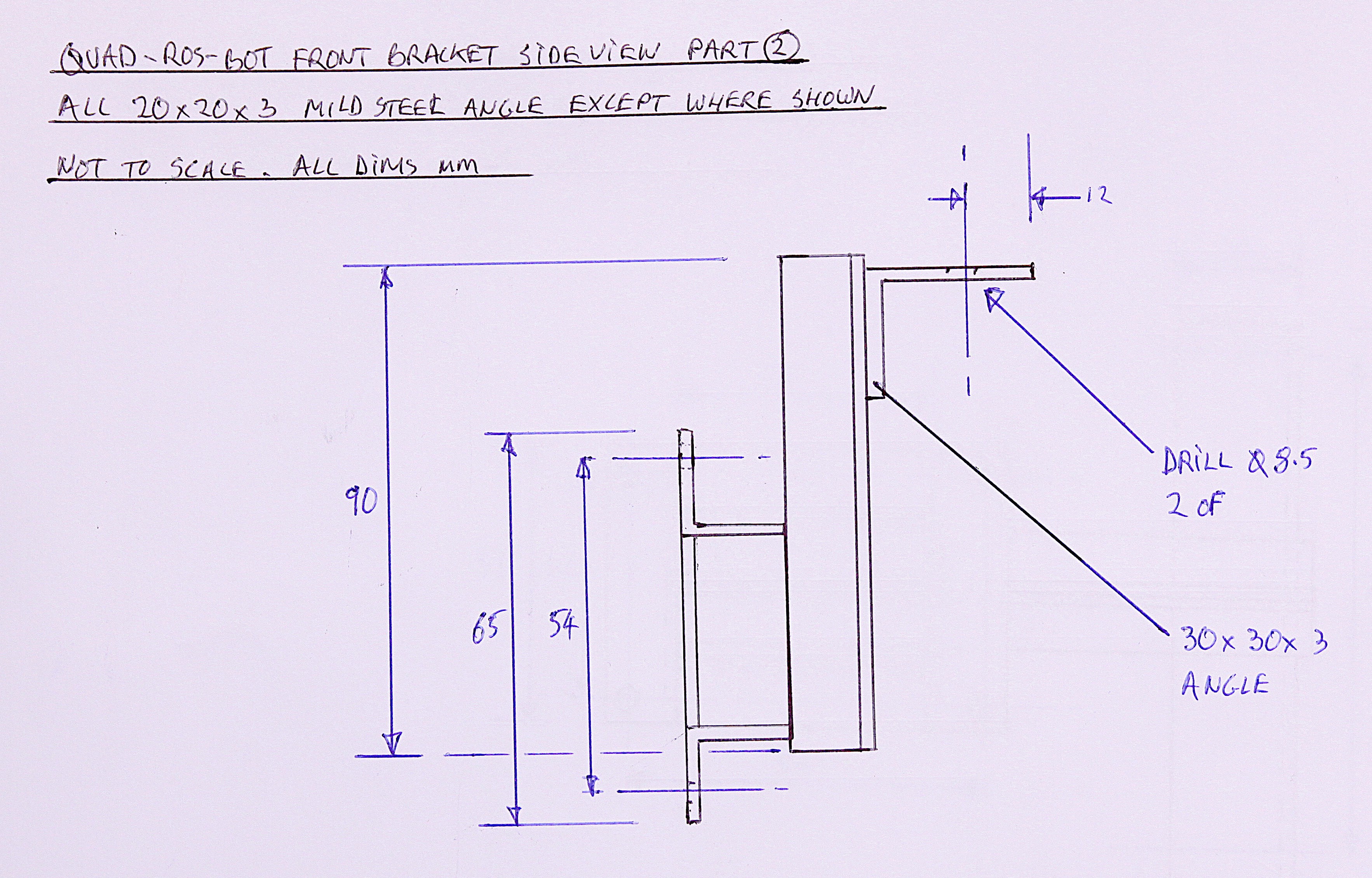
    We made some custom mild steel brackets to mount the actuator:

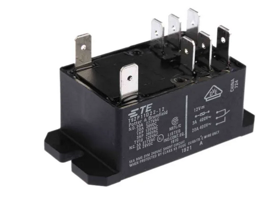
    ..... and used some 30 amp relays to handle the high current ( TE Connectivity, 12V dc Coil Non-Latching Relay DPDT, 30A Switching Current Flange Mount, 2 Pole) :

    Circuit diagram for the relays:

  • 3
    Front sub frame and steering position sensor mount


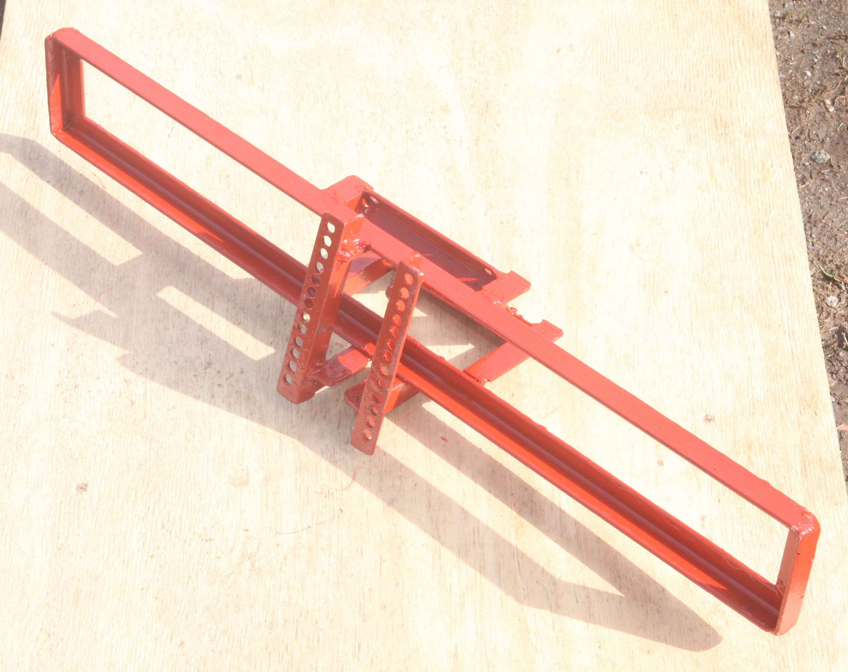
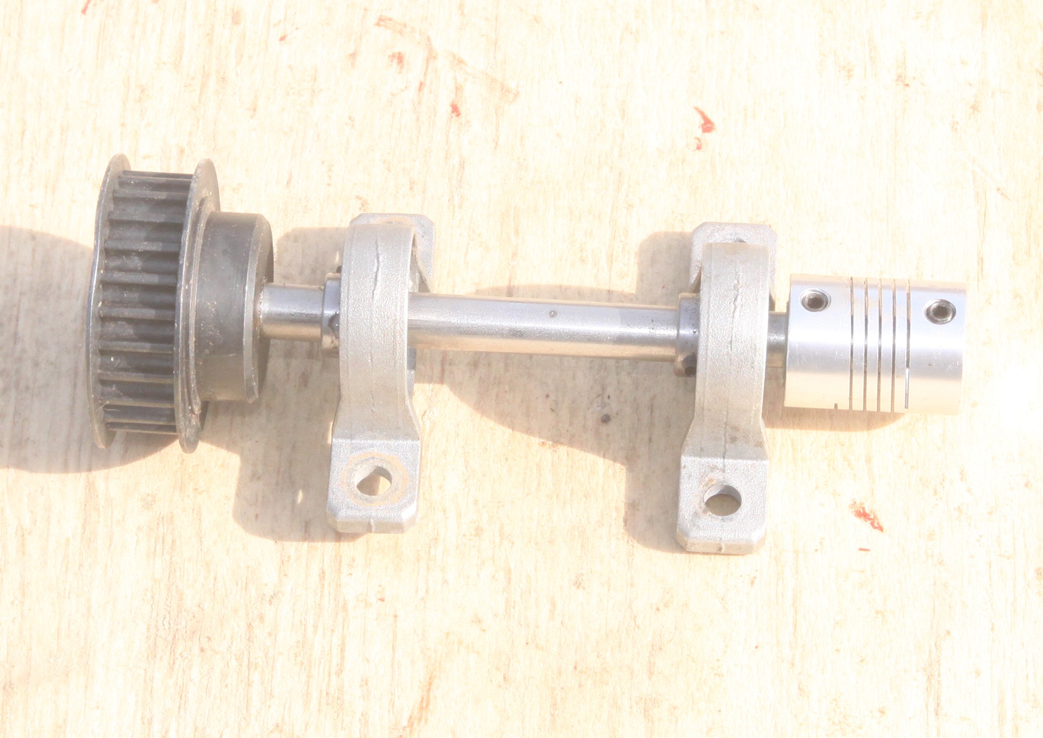
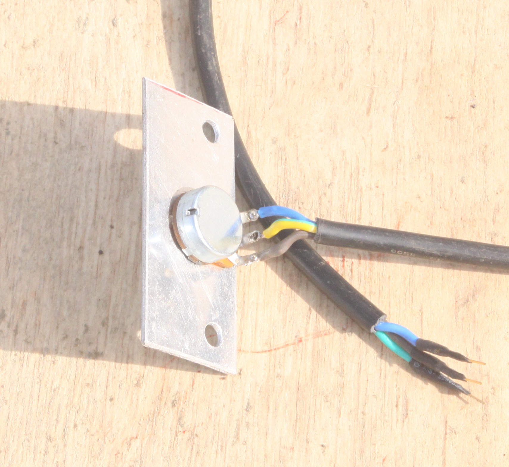
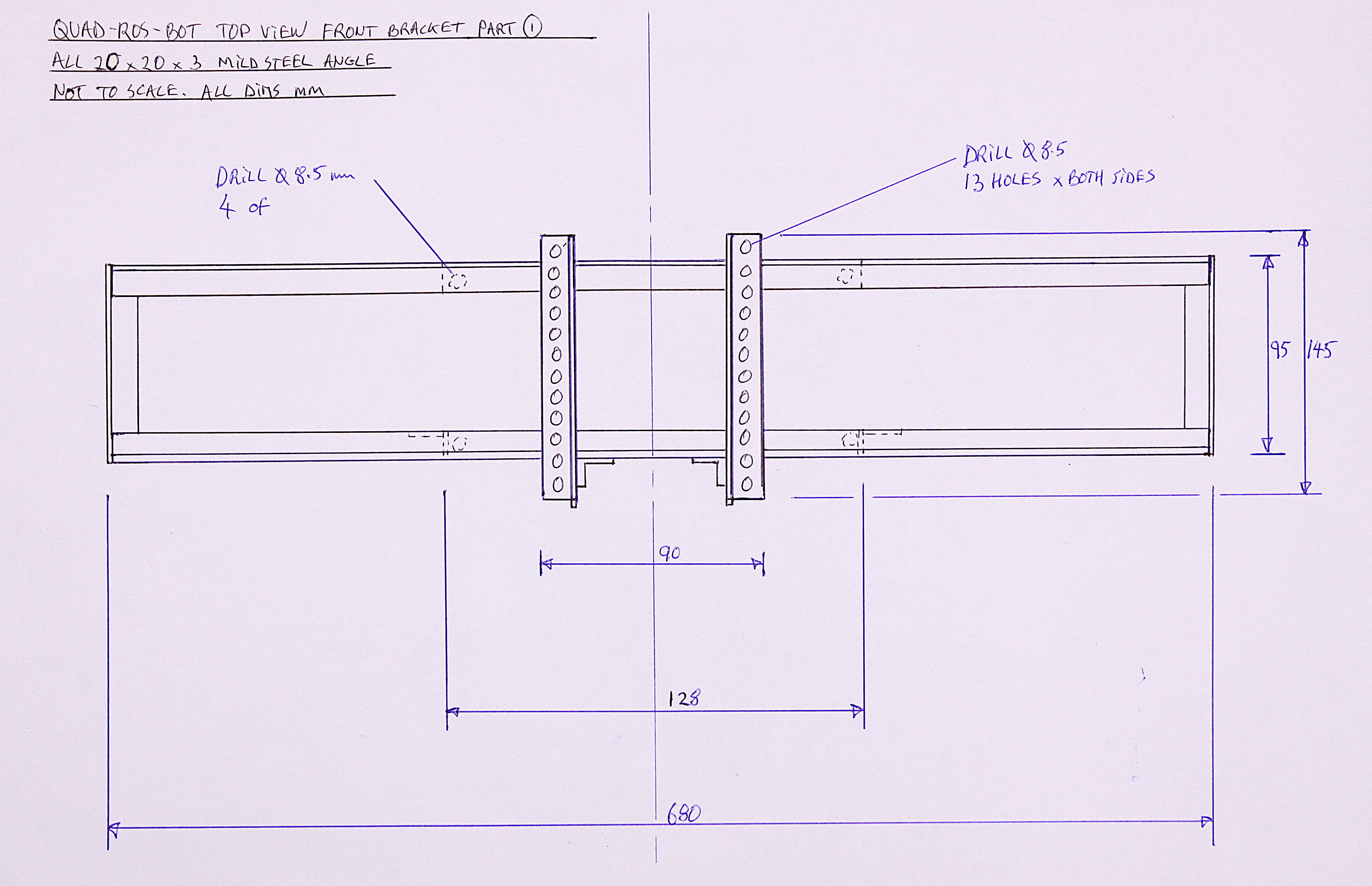
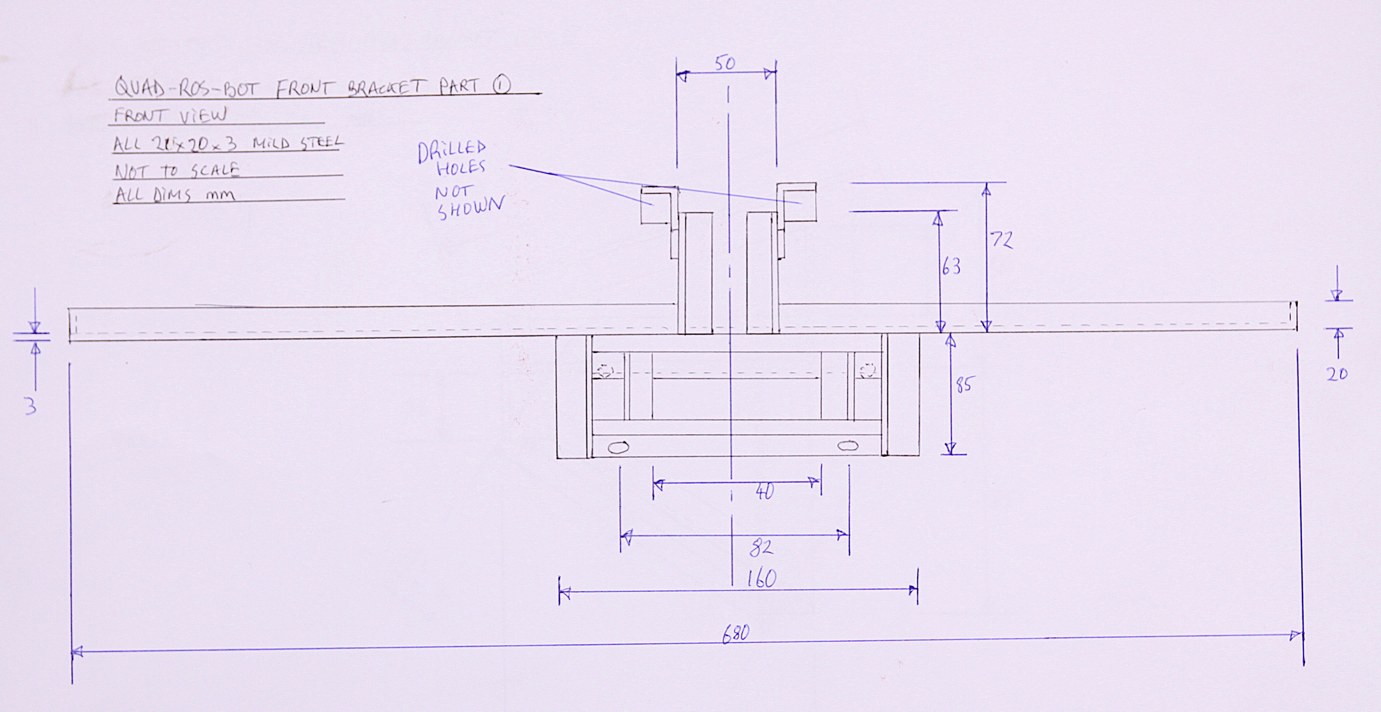
    This strange looking frame goes at the very front of the robot and performs two important functions. One is to mount a load of the sensors and antennae for the control system, and the other to mount an everyday 10K potentiometer to measure the steering angle. The steering angle is NOT measured by bolting the pot directly onto the top of the steering column , but via a gearing reduction timing belt to make better use of the pot's range and hence better resolution. This also has the benefit of hiding the pot deep within the frame work, well out of harms way. Video 3:

    All the photos and drawings needed to build the sub frame and bracket are given in this step, below. The important thing is to present the potentiometer assembly exactly parallel to the steering column or else the whole thing will fail and the belt might also come off the timing cogs. To prevent play, or backlash, the belt needs to be fairly tight, so the welding needs to be strong. The belt also needs some adjustment and this is enabled by the series of parallel holes drilled in the angle as seen in the photo above. Slots would also be a good option if a milling machine is available.

    The pot range and resolution was tested by using the Arduino Uno code below and we managed to get 340 units across the whole steering range, which is thought to be more than adequate. This could be further improved by using a gear ratio of 1:4 instead of 1:2.

    Code for testing the potentiometer:

    int sensorPin = A0;
    int ledPin = 13;
    int sensorValue = 0;
    
    void setup() 
    {
      Serial.begin(9600);
      pinMode(ledPin, OUTPUT);
    }
    
    void loop() 
    {
      sensorValue = analogRead(sensorPin);
      Serial.print("Pot value (0 to 1024):  ");
      Serial.println(sensorValue);
      digitalWrite(ledPin, HIGH);
      delay(250);
      digitalWrite(ledPin, LOW);
      delay(250);
    }

View all 4 instructions

Enjoy this project?

Share

Discussions

Muhammad Abdullah wrote 07/24/2024 at 15:16 point

Hi ! I am using a gas powered ATV. For the steering actuation I can use the Gimson Robotics GLA4000-S 12V DC Linear Actuator but what type of servo should I use for brake and throttle actuation.

  Are you sure? yes | no

Dan Maloney wrote 03/22/2021 at 18:15 point

That's a very promising platform for all-terrain robots. Where did you find that? I'm guessing Ali Express or something like that.

  Are you sure? yes | no

Capt. Flatus O'Flaherty ☠ wrote 03/23/2021 at 09:18 point

Hello Dan! I got this one off Ebay for £600 = about $750 USD. I'm sure they're on Alibaba as well, i did not look.

  Are you sure? yes | no

Similar Projects

Does this project spark your interest?

Become a member to follow this project and never miss any updates