 Joel Kozikowski
-
1Overview
There are five phases to this project:
- Download the STL files and 3D print the case
- Make the "Hat" PCB that sits on top of the Raspberry Pi
- Make the custom wires
- Assemble the unit
- Configure the Raspberry Pi and install the UI control software
A link to all components as listed on Amazon is available on this project's home page. The "Make the Hat" PCB is kind of chicken and egg. I am assuming that if you are interested in the project, you already have used at least one method of obtaining your own circuit boards (whether you've fabricated them yourself, or you've ordered them online). The Gerber files for the Hat is available on this project's GitHub page. Personally, I milled mine with a cheap desktop CNC machine that I have. An easier approach is to send the Gerber file to a fab house and wait for it to arrive while you are waiting to get all the other components from Amazon.
-
2Tools needed
In addition to the components listed, I needed the following tools to build and assemble the project:
- Dupont and JST pin crimper
- IDC ribbon cable crimper
- Wire stripper and cutter
- M3 thread tap (to make screw hole threads in 3D printed parts).
- soldering iron
- Hex screwdriver for M3 screws
-
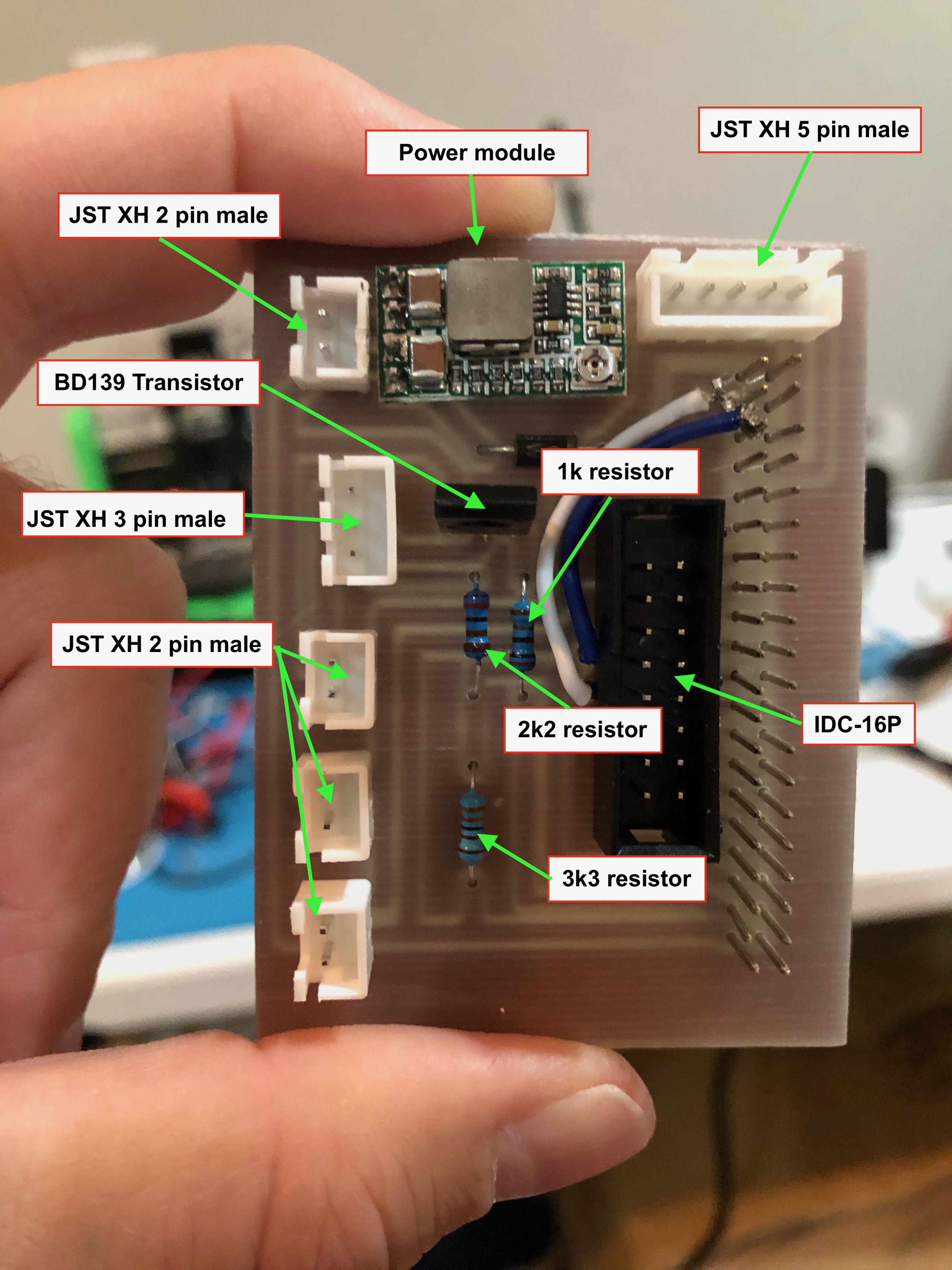
3Make the Pi Hat
I've placed the KiCad files, along with various versions of the traces on Github in the 'hardware' directory of the project. It's designed to be a single sided board to make it easier to make DIY style.

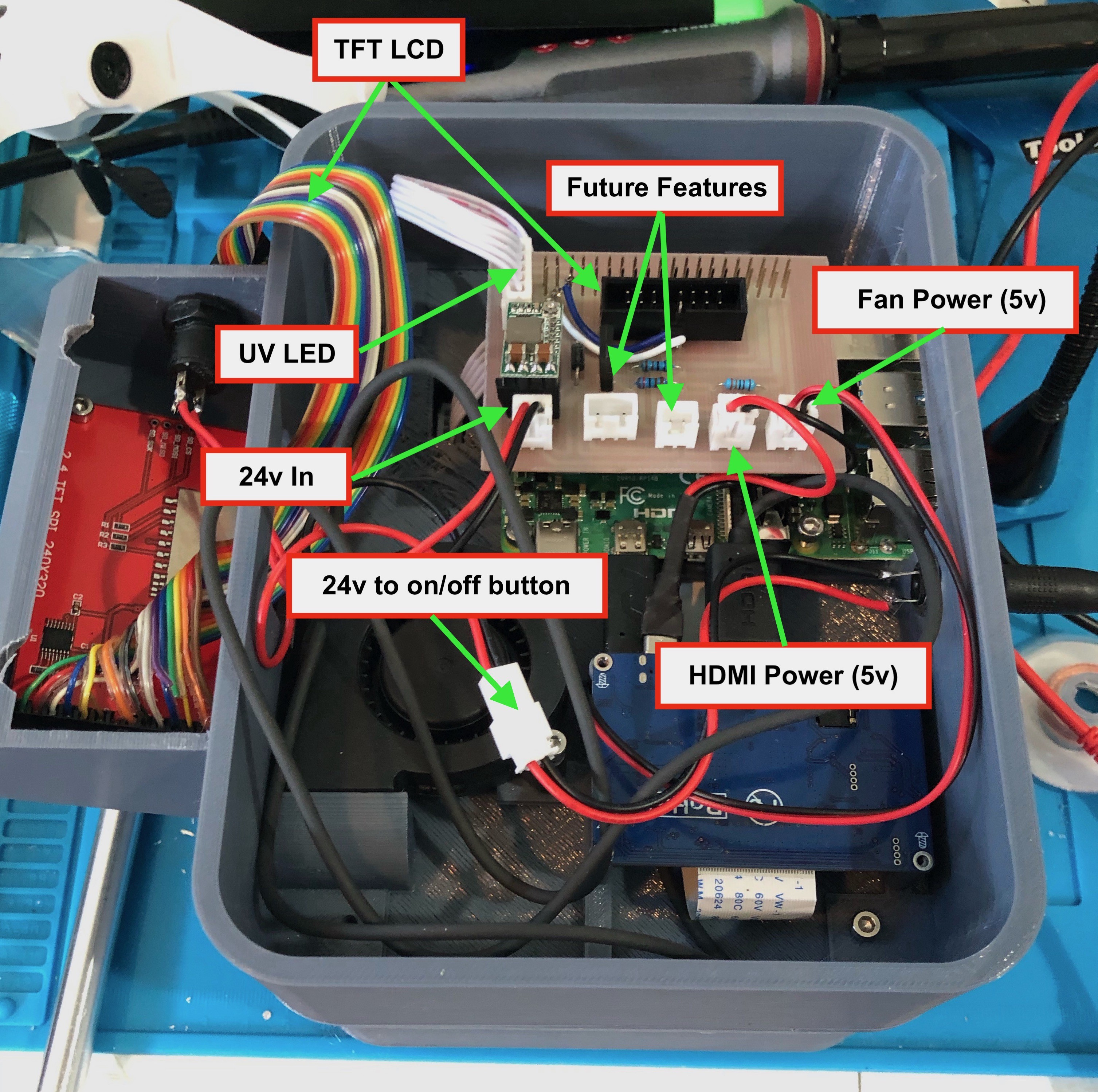
PiHat PCB The one "trick" I'm currently using to facilitate a single sided board is I'm using a 40 pin "stackable female header" (which is a female header with extra long pins). This allows the female side of the header to be mounted on the same side of the board as the copper layer, yet still be soldered on that side. Just be sure to leave a small gap (don't mount the header flush) which will make it easier to solder from that side.

Mounting female header copper (bottom) side When mounting the 2 pin JST female connectors, be sure to pay attention to the orientation of the connectors. If board is oriented so the Pi GPIO header is on the right, then the pins at the "top" are all power, and the pins at the "bottom" are all grounds. The component list includes pre-fabricated 2 pin JST header wires. My package came like this (one set placed in a female connector):
![]()
JST power connector orientation With that orientation, the connects are mounted on the Hat this way:
![]()
The power module is mounted first by soldering four header pins to the holes in the power module area, and then soldering the power module to the pins. This power module is used to convert the 24 volt input into 5 VDC, which is used by the Pi, the HDMI board, the fan, and the PiHat itself. You set the output of this power module either by turning the small screw until the output is how you want it, or you can cut the trace that attaches to the screw pot, and place a solder blob over the 5V connection to set the board's output to a constant 5 volts. I prefer to use the screw adjustment, as you can dial in a full 5 vDC AFTER the protection diode's small voltage drop. To do this, simply apply your 24v power to the JST XH 2 pin male component in the upper left hand corner, then measure the voltage on pin #2 of the GPIO connector (pin #2 would be first/top row, second/right column on the 40 pin connector). Pin #39 (last row, first/left column) is Ground on this board. Dial the screw until 5 volts appears.
The white and blue wires shown on the picture above are two additional traces (a poor man's double sided board) that add the Pi's I2C interface pins (SDA and SCL) to two currently unused pins on the IDC-16 connector. I'm doing some experiments here that uses I2C, but the current iteration of this build does does not need them. This connection IS in the design and Gerber files in GitHub, but they take this board from a single sided board to a double sided board if you are going to have your board commercially built. There are two small via holes near the IDC connector that the other end of the wires connect to if you are doing DIY but want to use them for your own experimentation.
-
4Make custom wiring
There are a couple of custom wires with connectors that need to be made.
The requires wire connectors are:
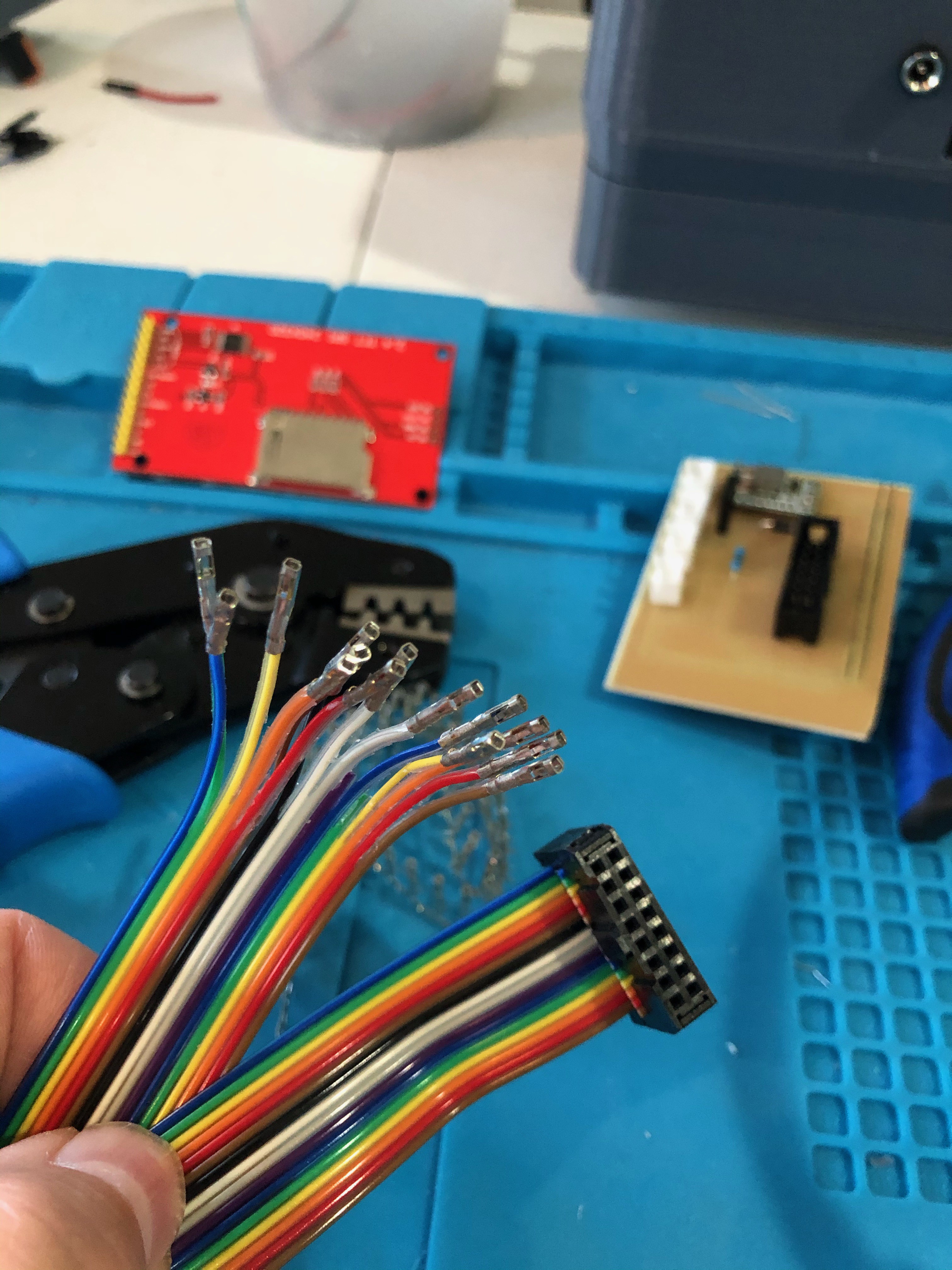
- 16 connector IDC female to Dupont female (for PiHat to TFT touch screen)
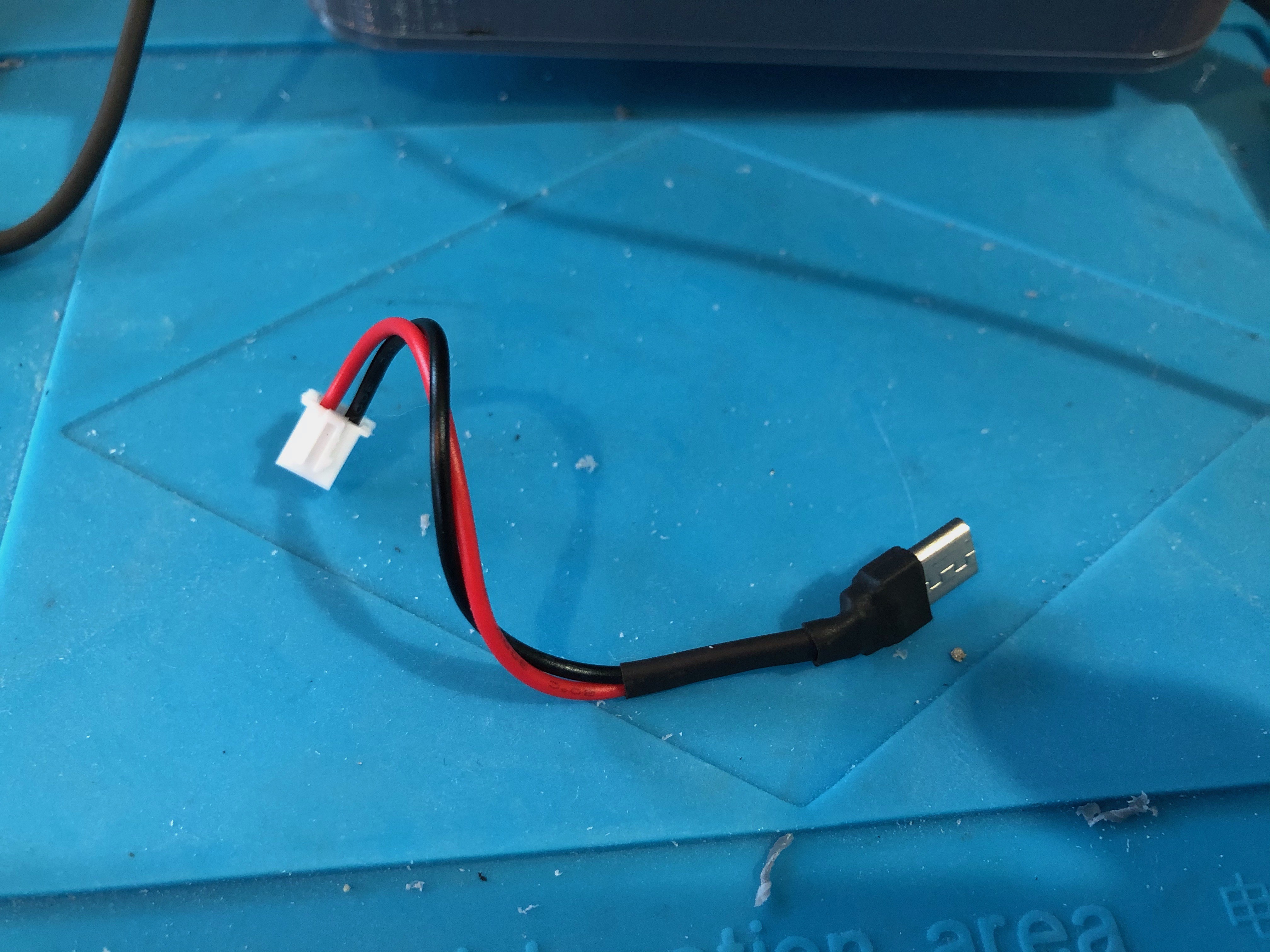
- JST XH 2 pin female to Micro USB (to power the HDMI board for the Sharp LCD)
- JST XH 5 pin female with leads (for the UV lamp - must be made if you don't have the original)
- JST XH 2 pin female to female barrel connector (for power input)
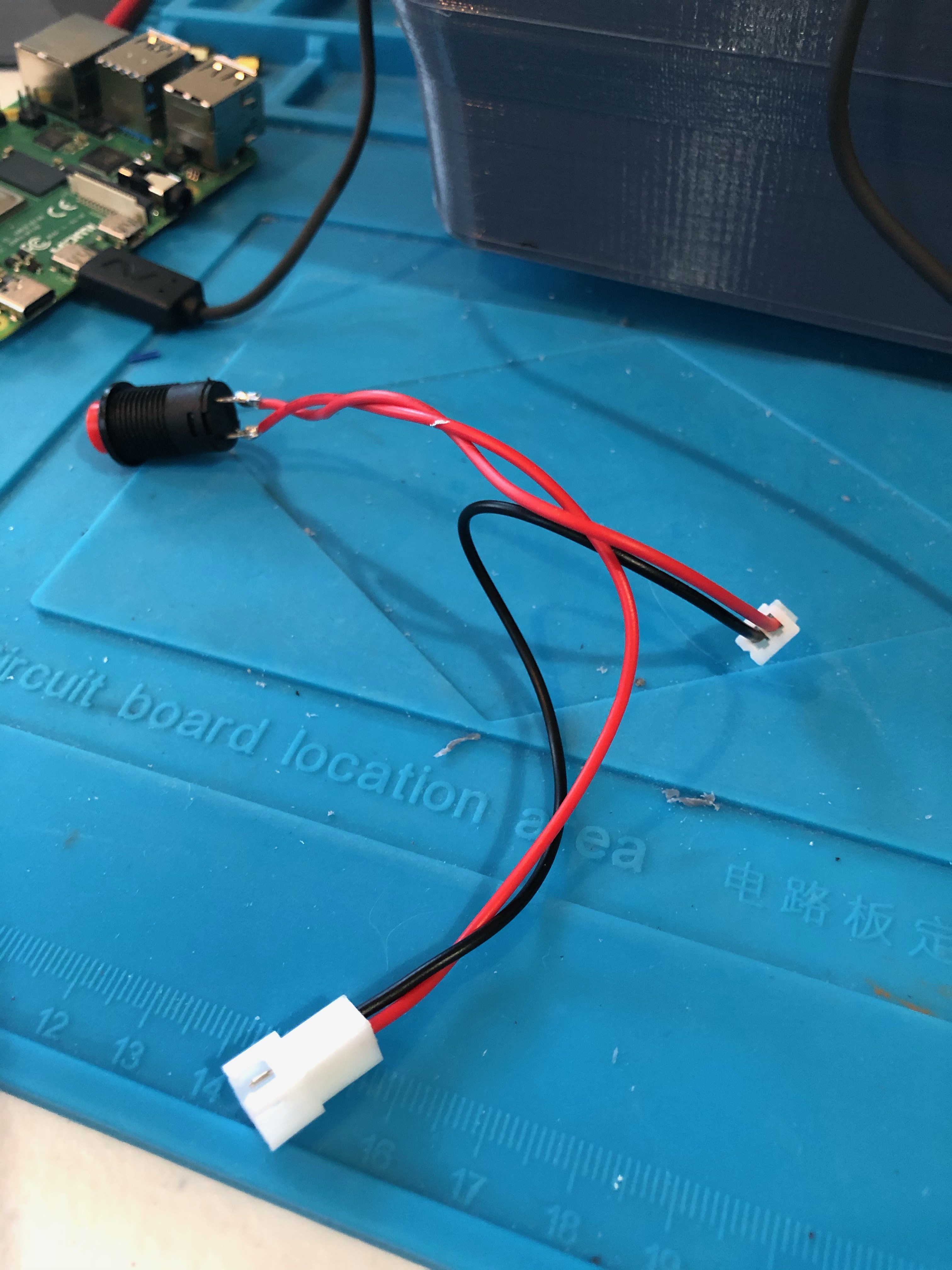
- JST XH 2 pin female to JST XH 2 pin male to pushbutton (for power control)
Note that if you are lazy, you can cheat and wire the female barrel connector to the pushbutton to a single JST XH 2 pin female to attach to the PiHat, eliminating the need for #5. Having #5 makes it easy to take things apart and put back together without having to cut wires. If you are super lazy, you can eliminate the button altogether, and plug the barrel connector directly into the PiHat. You'd then turn the unit on and off by disconnecting the 12V power supply.
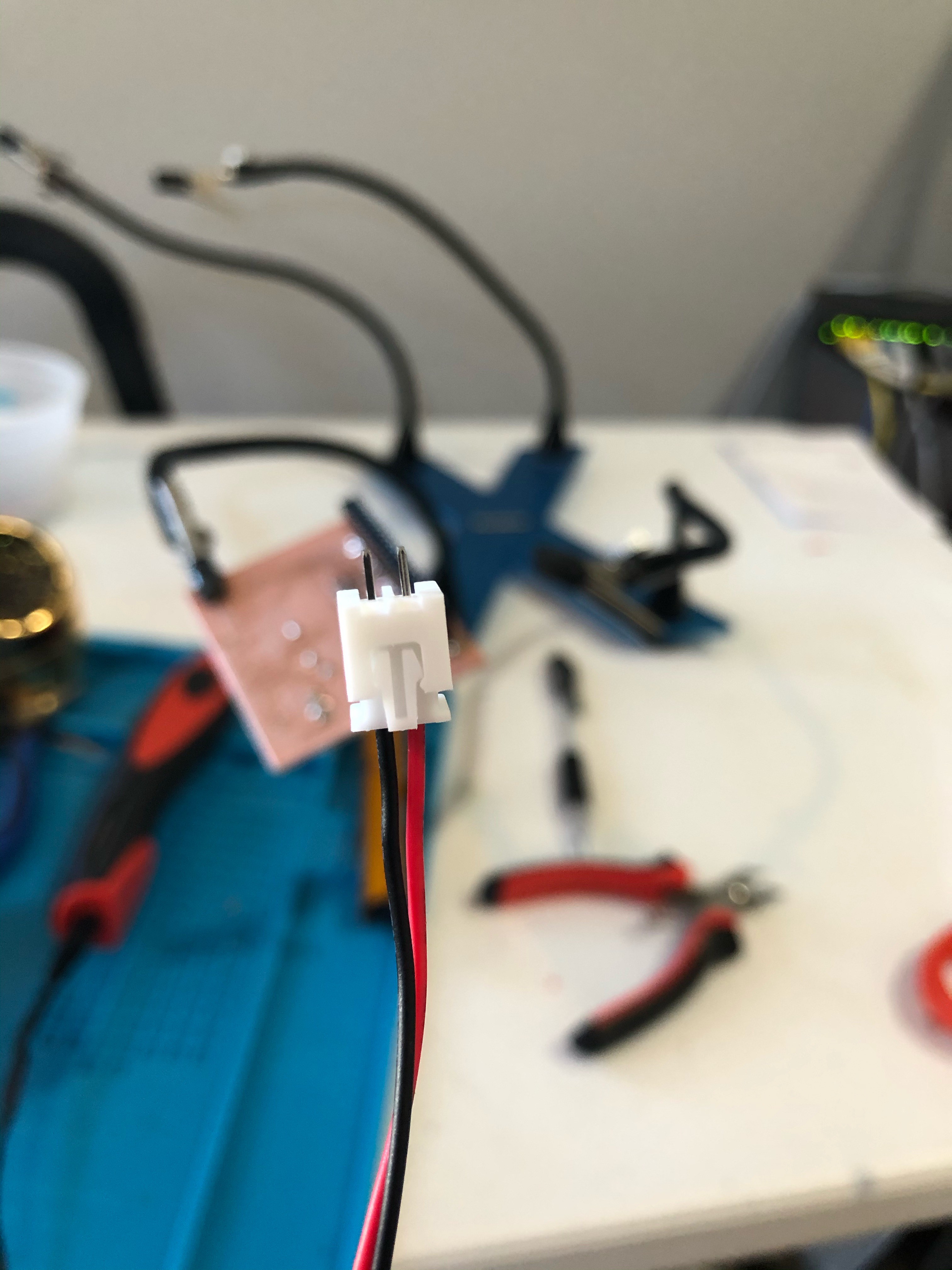
Notice that list contains a lot of 2 pin JST connectors. To speed this process, I took the simple approach and purchased an inexpensive 2 pin JST wire set (listed in the components list). This gave me 10 sets of:
- Two wire lead with female connector
- Two wire lead with male connector
- Two pin surface mount male connector
The IDC to Dupont is to connect the PiHat to the TFT touch screen. There is a PDF in the Github repository that shows exactly what the pin connections are
![]()
IDC to Female Dupont cable for touchscreen ![]()
JST to USB to power the HDMI board ![]()
Pushbutton for unit power I didn't take a picture of the barrel connector to JST female by itself. Its pretty straight forward, however. See the assembly pictures for an example.
The are only two other connectors. One is the UV LED, (which is simply one of the pre-fab 2 pin leads soldered directly to the UV lights. That is listed in the assembly step. The other is a JST connector crimped on to the bare wires of the cooling fan. That one should be straight forward also.
-
5Assemble the UV LED section.
A previous version of this build used blacklight LEDs in a strip light. That was found not to work, as the UV light produced was not only not strong enough, but lack of beam focus caused blurry edges around the resulting exposed board.
To fix this problem, a pre-manufactured UV light lamp is borrowed from a Sparkmaker mSLA printer. You can either cannibalize one from a used printer purchased on eBay, or order a replacement part on line (one example source is here).
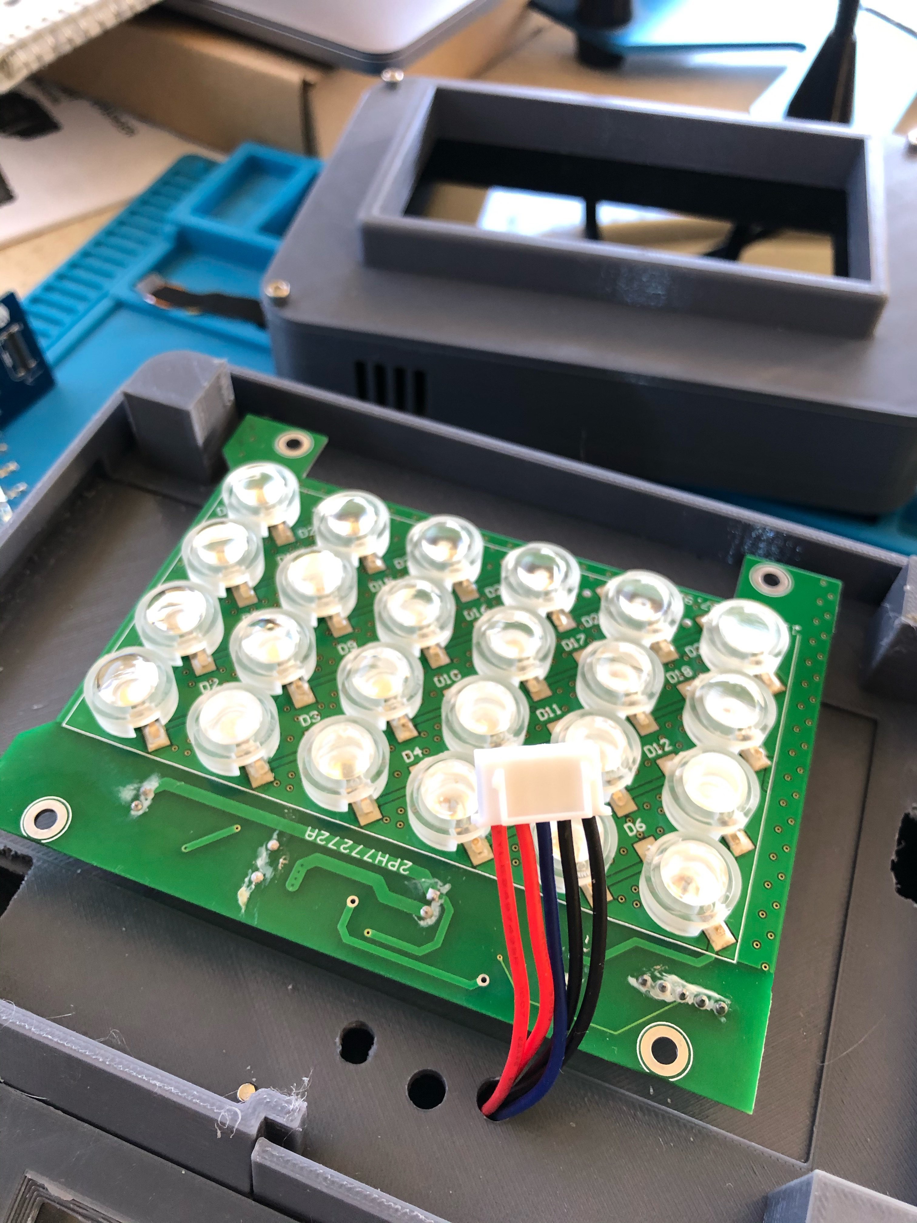
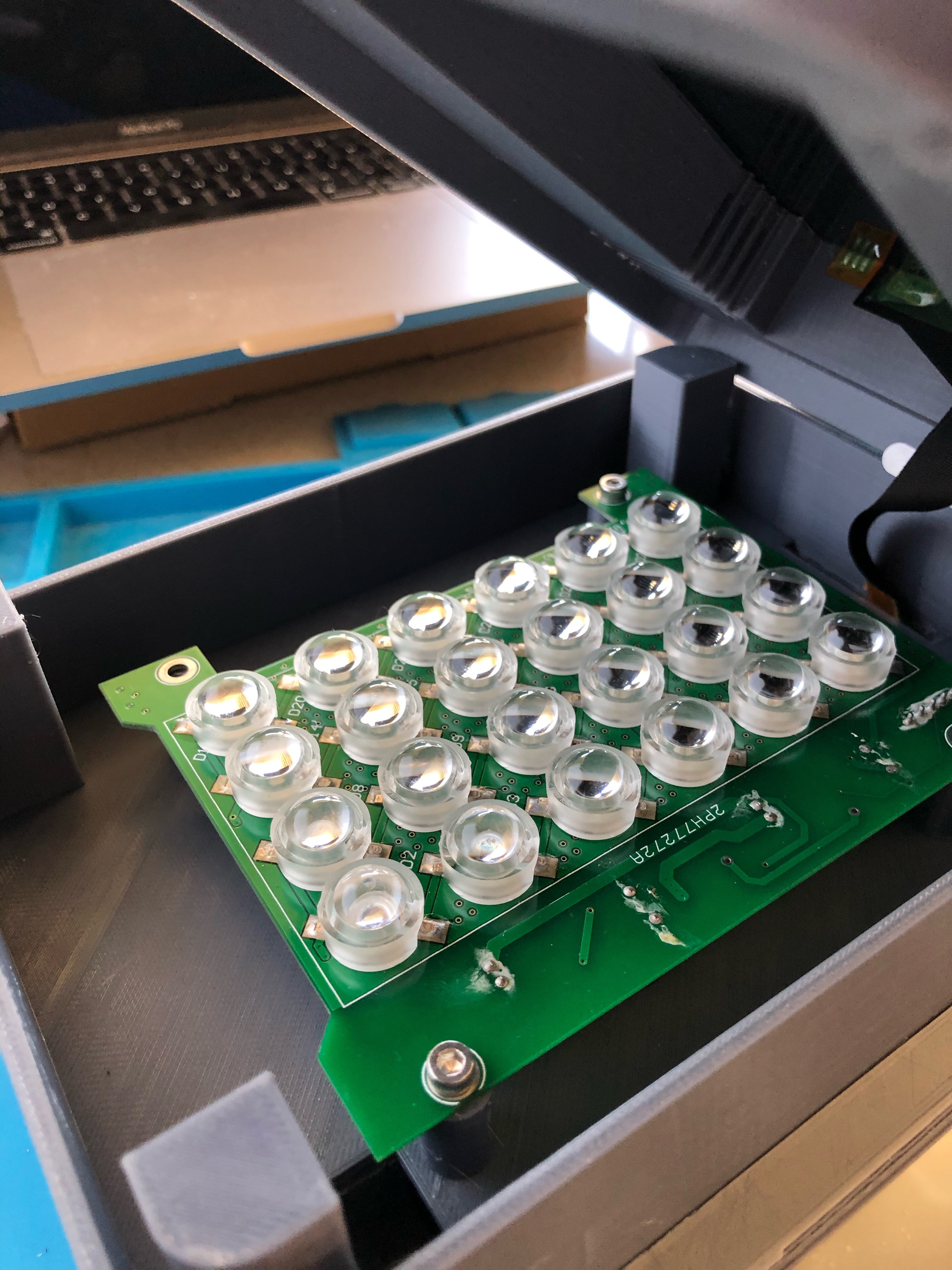
The Sparkmaker lamp is powered by 24V. There is a 5 pin JST-XH connector on the board used to power and control it. The two pins on the left are 24V. The two pins on the right are ground. The pin in the middle is a "control" line that controls the brightness using PWM. This pin accepts 3V to 5V, so it can be powered directly by the Pi's GPIO pin. The picture shown here show is from a prototype with red wires for positive, black wires for ground, and the middle wire (which is blue) for the control. However, the 5 pin JST connector on this Sparkmaker board can be connected directly to the 5 pin JST connector on the Pi hat using the cable that comes with the lamp.
![]()
-
6Exposure LCD assembly
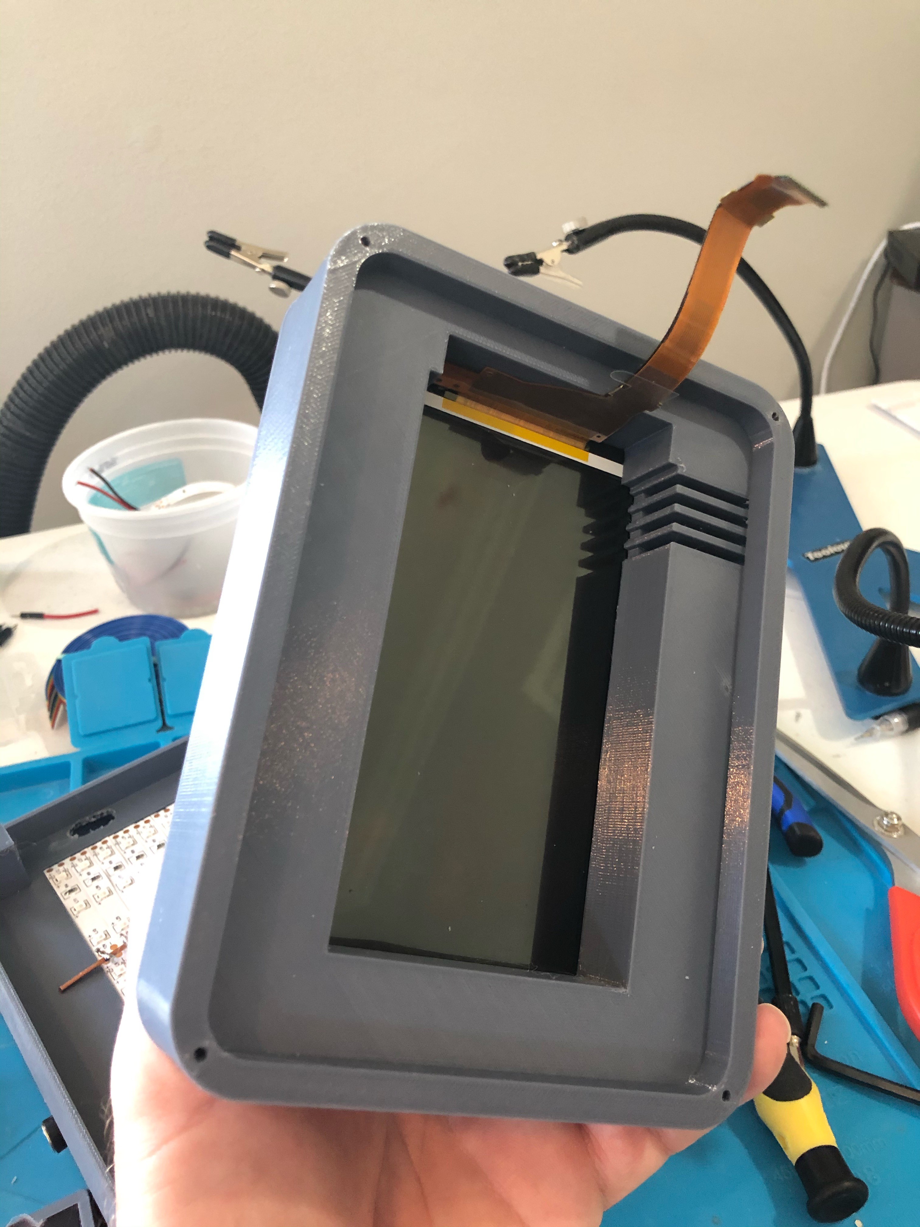
Place the Mars Pro replacement screen on the 3d printed part named "ScreenBase". Note that for best results, this should be placed GLASS DOWN (that is, the glass should be the layer you see directly in the view below). Run the "flexible flat cable (FFC)" or the LCD through the slot to the opposite side of the screen base. The screw holes you see on this part are not printed with threads. Use an M3 tap to carve out some threads in these holes.
Place the part named "Alignment frame" over the screen, then screw the two parts together using M3 screws.
![]()
Rear of screen base with LCD cable placed correctly -
7Prepare Raspberry Pi
There is a lot of software setup that needs to be done on the Raspberry Pi. Most of it can be done after the unit's assembly, but you at least need to flash an SD card with the Pi OS, set it up for remote access, and place the SD card in the Pi before it gets buried under all the other components.
Follow the first five steps in the Qwicktrace software setup README. This will prepare the Pi to be booted and accessed remotely. You can finish all the steps before you install it, or after you have put everything together, depending on your build confidence :P
-
8Final assembly
Things go pretty quick from here.
Run the FFC of the LCD thru the slot of the LED holder:
![]()
Place the two parts together, and flip the unit over:
![]()
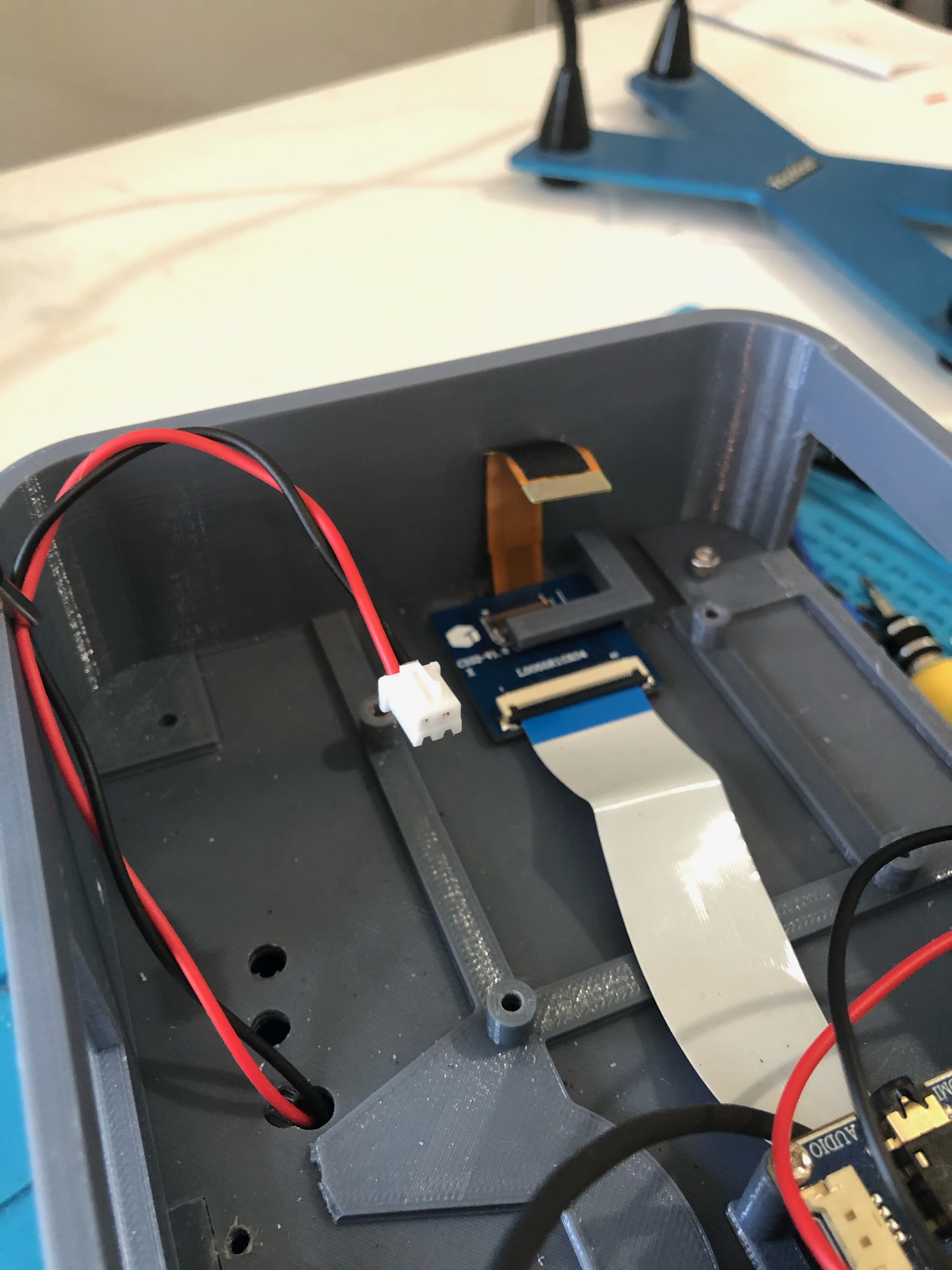
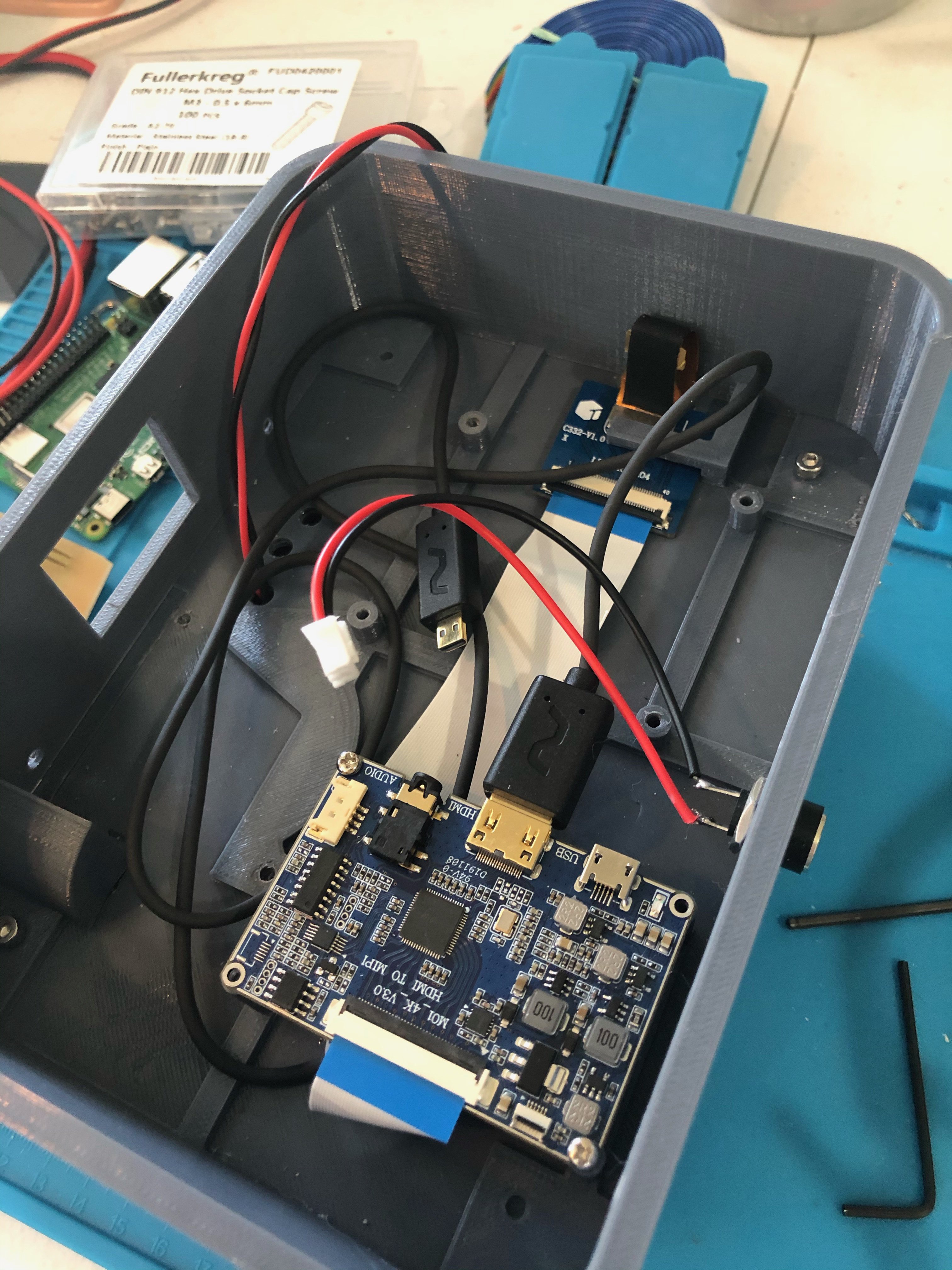
Underside of LED holder, with LED cable and FFC visible Also in the picture above is the HDMI board, and the its associated interface board for the Sharp LCD. Screw the HDMI board to its posts. Attach the FFC cable to the connector board, and slide under the L shaped arm.
![]()
Power input and HDMI cables in place Attach the barrel connector, and solder one last two pin female JST with leads to it. Connect the "standard" male HDMI connector of the thin HDMI cable to the HDMI power board as shown above.
Next up is to attach the TFT touch screen and button assembly to the "control housing". The header pins of the TFT screen should be on the opposite side of the button. If you wired the button separately as recommended, you will end up with two connectors like this:
![]()
Control housing with power button and TFT screen Attach the housing to the base, running the wires through the opening and into the bottom section of the unit:
![]()
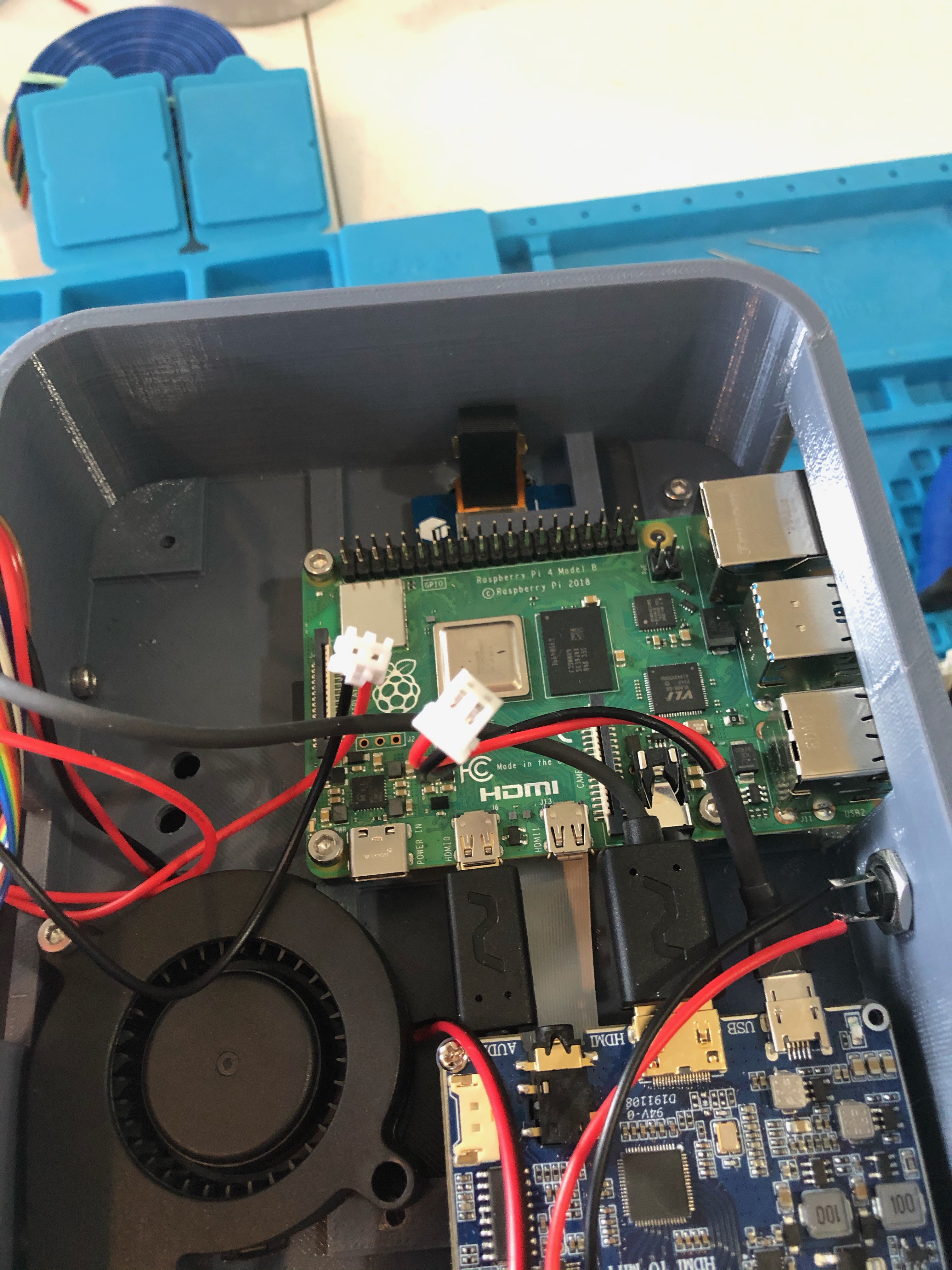
Control housing mounted Mount the Raspberry Pi, and the fan:
![]()
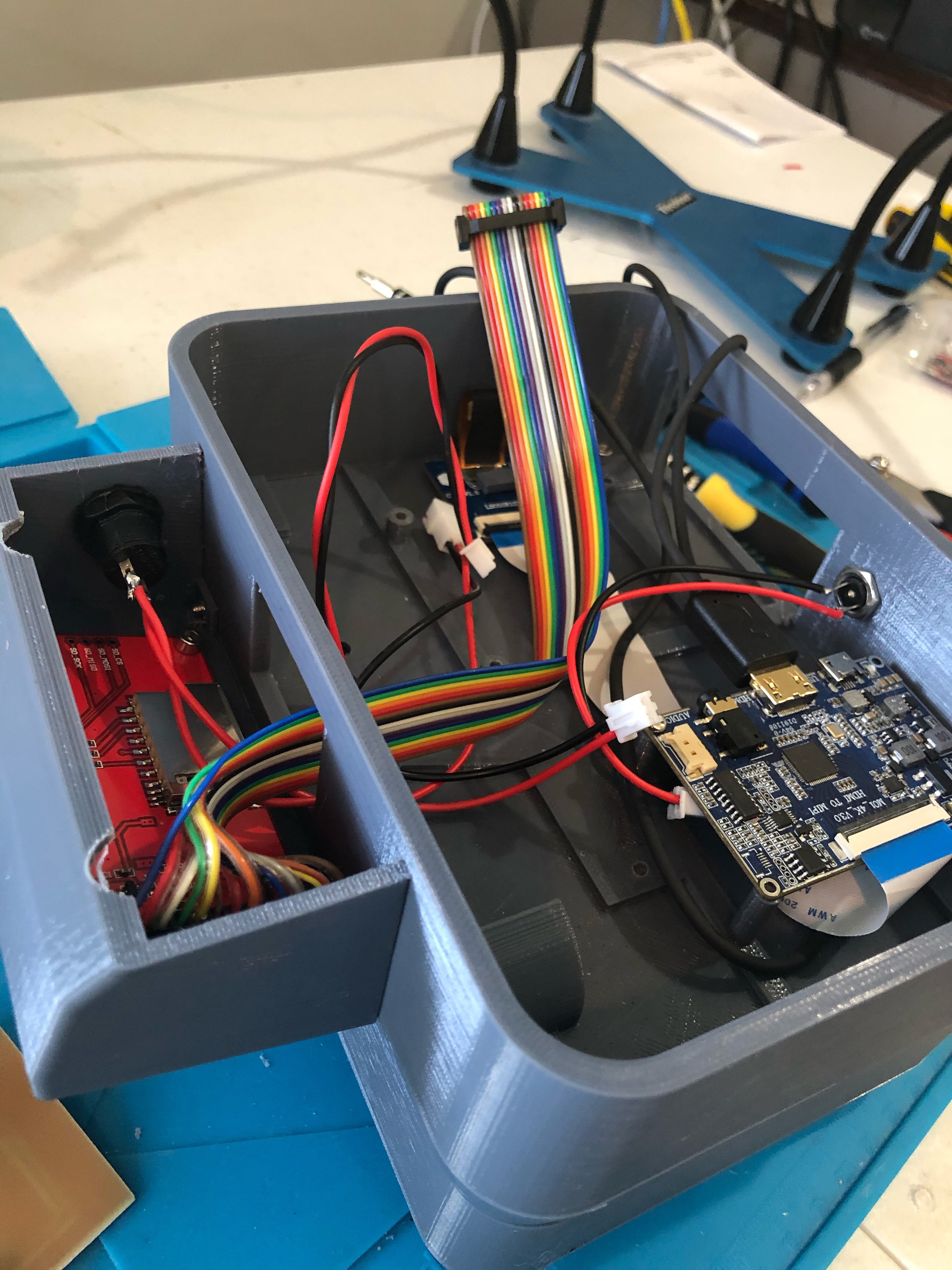
Raspberry Pi 4 and Fan mount Place the PiHat on the Raspberry Pi oriented as shown in the picture. Connect the various wire runs to the appropriate PiHat connector. The barrel connector (power in) connects to the button assembly, and the button assembly connects to the PiHat power (unless you were lazy, in which case connect the barrel connector directly to the power in on the PiHat.
![]()
Complete (almost) component assembly The above picture does not have the touchscreen cable connected to the ICD16 connector. This was to make the picture clearer. Connect the touchscreen cable, and you are done with the assembly!
-
9Install software
Plug the unit into a 12 volt power supply, boot the Pi, and follow the rest of the instructions found on the README in GitHub.
Qwicktrace PCB
A "smart" exposure table for small photosensitive PCB etching using Raspberry Pi 4 and LCD from SLA resin printers


Discussions
Become a Hackaday.io Member
Create an account to leave a comment. Already have an account? Log In.