 zpekic
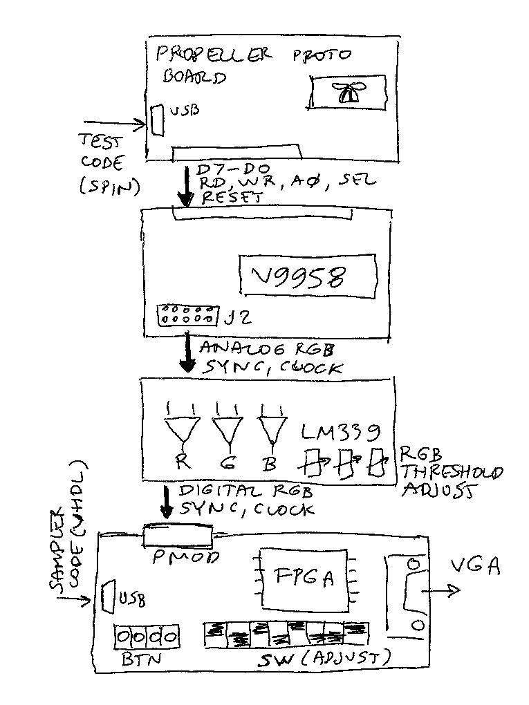
The sketch below describes key hardware components of this proof of concept:
Propeller proto-board
This board is out of production, but any proto-board with Propeller can be used. It is convenient that the number of signals that need to be driven is small: 8 data + 4 control lines only. So smaller boards with 16 connections to the breadboard are sufficient.
V9958 board
I used the high-quality kit board originally meant for rosco-m68k MC68000 computer. Few small hardware hacks were needed because the board adapter is set for MC68000 bus (J1), and Propeller allow direct interfacing with VDP, without glue logic. So I removed one GAL from the board, and connected the /RD and /WR signals directly, bypassing the Motorola bus R/nW logic.
I use the J2 output pins to tap into the VDP signals (not the DIN output)
Flash A/D board
This one is described separately, but is nothing more than 3 voltage comparators with potentiometers to tweak voltage cutoff separately for R, G, B and some pull up resistors on outputs. The result is RBG 3-bit digital color signal.
FPGA board
I used Mercury FPGA, a very convenient, economical and high quality board from MicroNova. Older Xilinx FPGA chip can be programmed using old but free ISE14.7 IDE, and the baseboard has VGA output. The signals are coming through PMOD. PMOD has 8 I/O pins, in this case 6 are used, 3 for RGB and 3 for control signals (HSYNC, CSYNC, CPU_CLOCK = XTAL/6)
Discussions
Become a Hackaday.io Member
Create an account to leave a comment. Already have an account? Log In.