 zpekic
Unlike their TMS99X8 video display ancestors used in MSX (and many other home computers and game consoles), the Yamaha V9938 / V9958 VDPs generate analog R, G, B along with sync signals:
| Variation | Output | Input | DRAM |
|---|---|---|---|
| TMS9918A | 60Hz NTSC composite | 60Hz NTSC composite | 16k x 1bit |
| TMS9928A | 60Hz YPbPr | 16k x 1bit | |
| TMS9929A | 50Hz YPbPr | 16k x 1bit | |
| TMS9118 | 60Hz NTSC composite | 60Hz NTSC composite | 16k x 4bit |
| TMS9128 | 60Hz YPbPr | 16k x 4bit | |
| TMS9129 | 50Hz YPbPr | 16k x 4bit |
The voltage level on RGB outputs is in the following range:
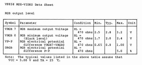
The threshold voltage level must be set somewhere above VRGB0 and below VRGB7 - matched to the specific VDP driving the circuit.
To feed the FPGA with digital R, G, B, an A/D converter is needed. There are two main concerns here:
- speed: the pixel clock is XTAL/4 = 21.47727/4 = 5.3693175MHz. This means the A/D conversion must complete in time much less than 185ns
- resolution: the absolute minimum needed is 1 bit - color is present or not
One could of course use fast, high-precision, and expensive A/D converters. But for the proof of concept purposes, a super cheap voltage comparator circuit is sufficient:
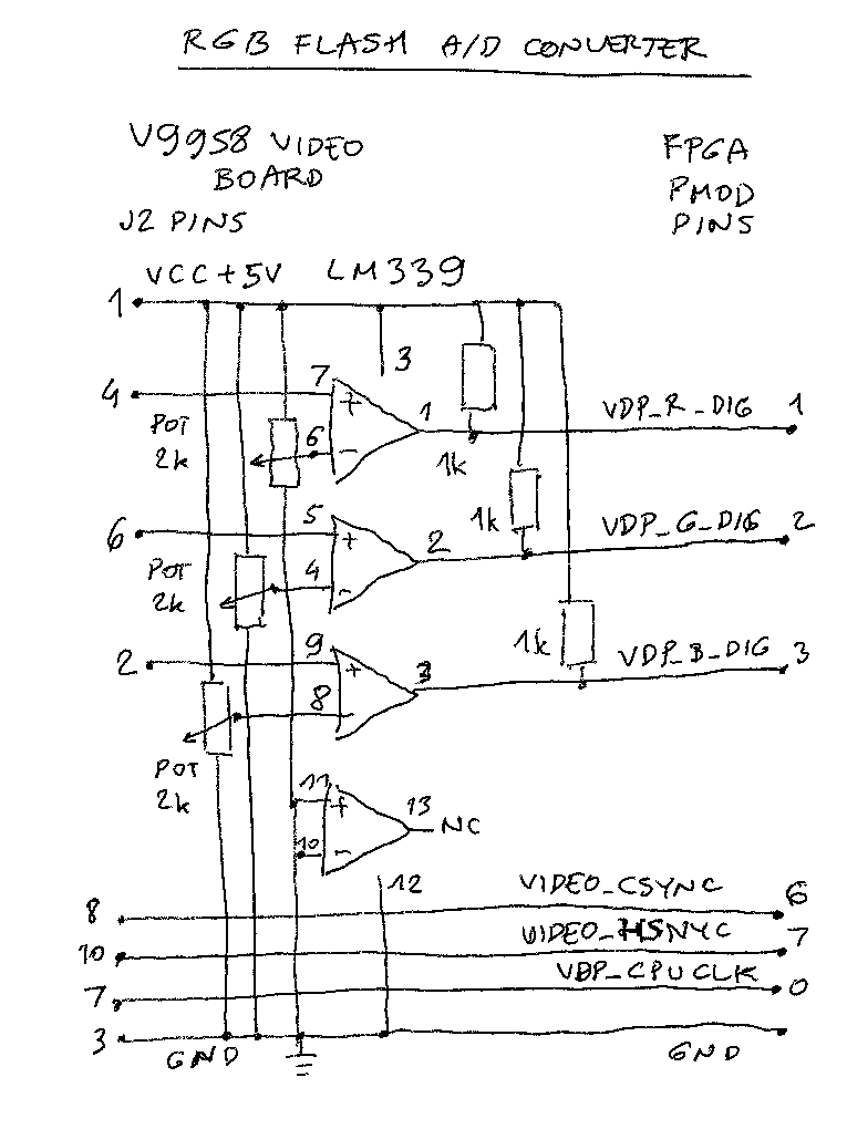
When the voltage LM339 on + input is greater than - input, the output is "high" - meaning color is detected.
The voltage cutoff point is determined by running the demo code and and tweaking the potentiometer positions with a screwdriver until the colors looks acceptable:
The 1k pull-up resistors are pure ad-hoc improvisations too, prototyping the circuit on the breadboard I found that having them increases the picture quality, probably by generating faster output rise times.
Other signals are directly led from VDP to FPGA:
- VIDEO_CSYNC - this signal contains both VSYNC and HSYNC components. The VSYNC is extracted in the FPGA from it. VSYNC frequency is 15.7kHz/262 = 60Hz.
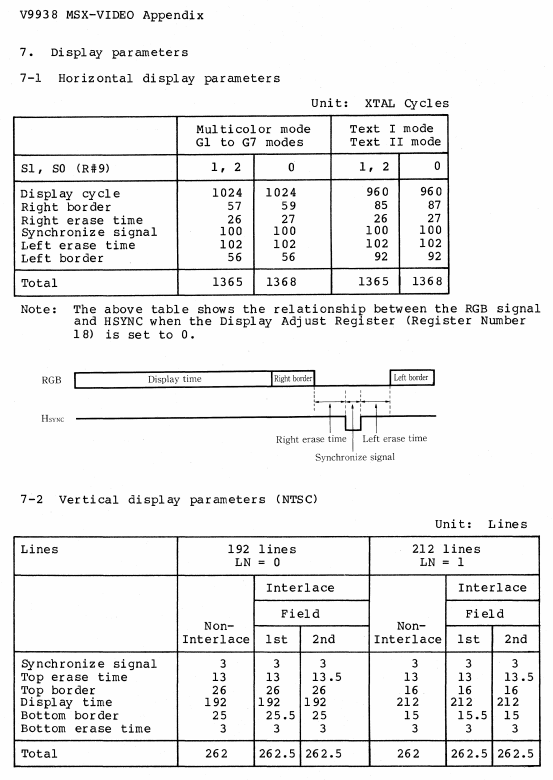
- VIDEO_HSYNC - positive pulse denotes start of new scan line. The frequency is XTAL/ 1368 = 15.7kHz
- VDP_CPUCLK - this is XTAL/6 = 3.579545MHz signal. It is used to multiply with 12/2 in order to regenerate XTAL frequency inside the FPGA
Discussions
Become a Hackaday.io Member
Create an account to leave a comment. Already have an account? Log In.