 Dominik Meffert
While there is still much work to do on the charging electronics, the current fluid system design can be considered complete. It's been working reliably for about a year now, with only minor changes from time to time to make it even more reliable.
So, I thought now would be a good time to remove parts that are not essential to reduce cost and complexity. Currently, the frame has a large size of about 100*50cm, which I plan to reduce to at least half its size over time.
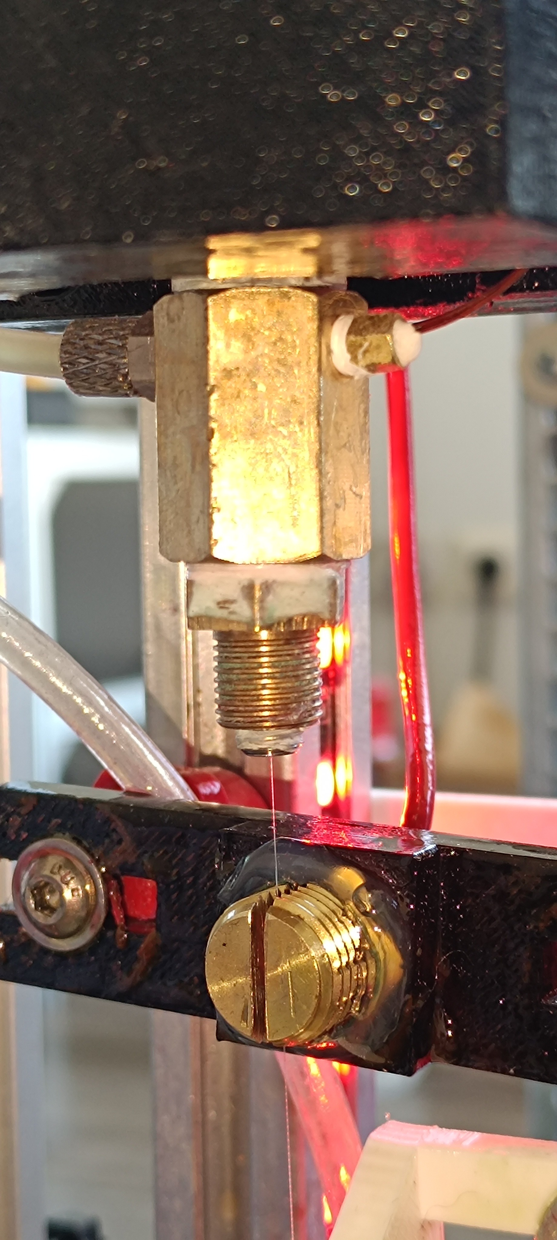
Falling Ball Viscosimeter
One thing that sometimes caused problems was the falling ball viscosimeter. When not used for a while, it happened that the steel ball got stuck at the bottom of it, and it was needed to disassemble it, clean all parts with ethanol, and assemble it again. Since the falling ball viscosimeter became redundant by using a ratio of pressure divided by jet velocity for the viscosity reading, I thought it would be better to remove it to have one less point of failure on the machine. So, I removed all parts of the viscosimeter, including the 2 inductive sensors, the polycarbonate tube with steel ball, and the fittings.
Peltier Heater / Cooler
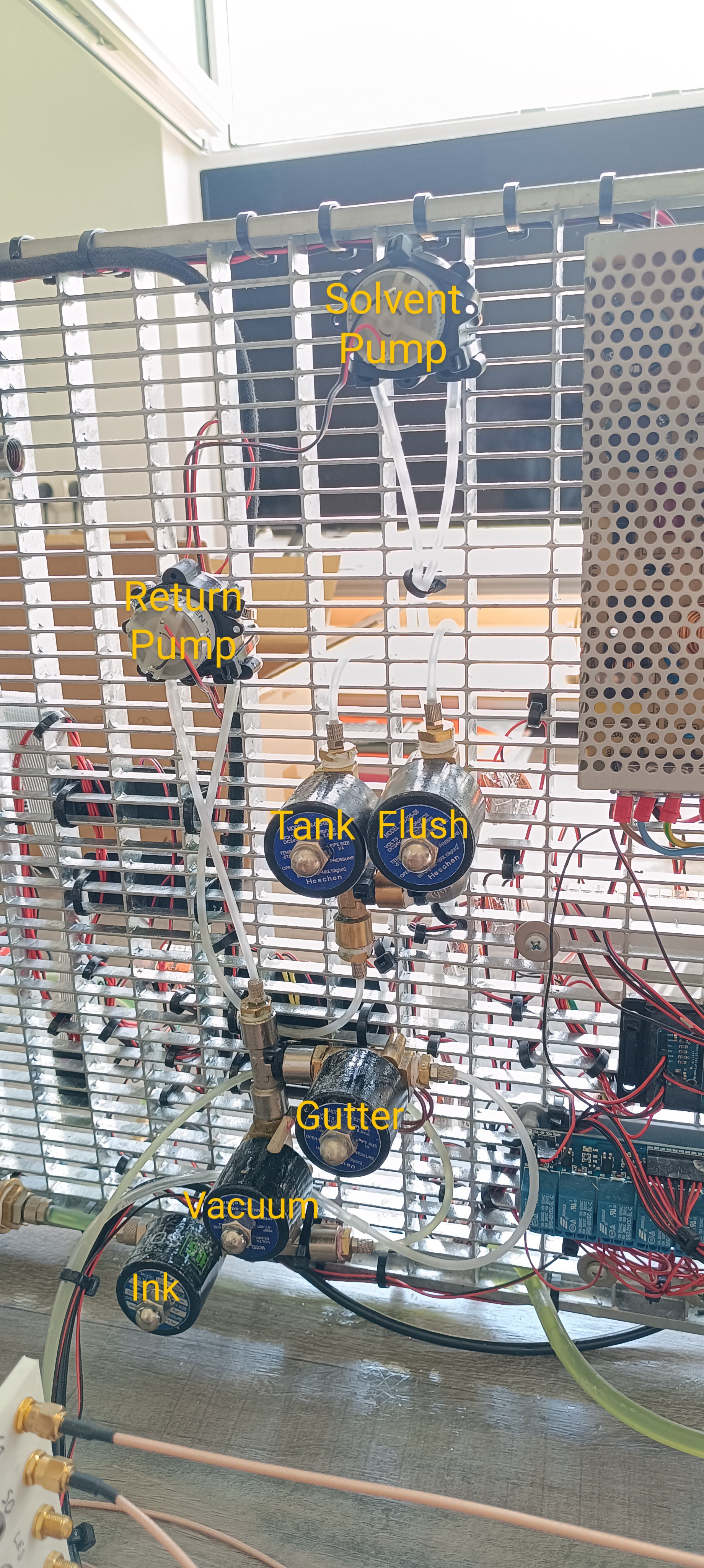
With these parts removed, there was still the brushless pump for circulation and the Peltier cooler/heater left. The circulation line is used for mixing the ink with solvent when the jet isn't active. It also has a higher flow rate than the inkjet and is used for pushing the ink through the main filter to keep it clean. So, the circulation line had to stay.
The heater/cooler was used for keeping the ink at a reference temperature of 25⁰C when using the viscosimeter because viscosity changes with temperature. With the viscosimeter removed, there is no need to keep it.
To still be able to take temperature changes into account, I finally added a temperature sensor to the nozzle assembly which reads the temperature as close as possible to the ink jet before it performs the TOF reading.
Maybe this can later be used for temperature compensation of the viscosity reading.
Brushless Pump
Now the big question was what to do with the brushless circulation pump.
At the time, I decided to remove it and replace it with another peristaltic pump to only have two different sorts of pumps on the printer instead of three. Later I found another solution to it.
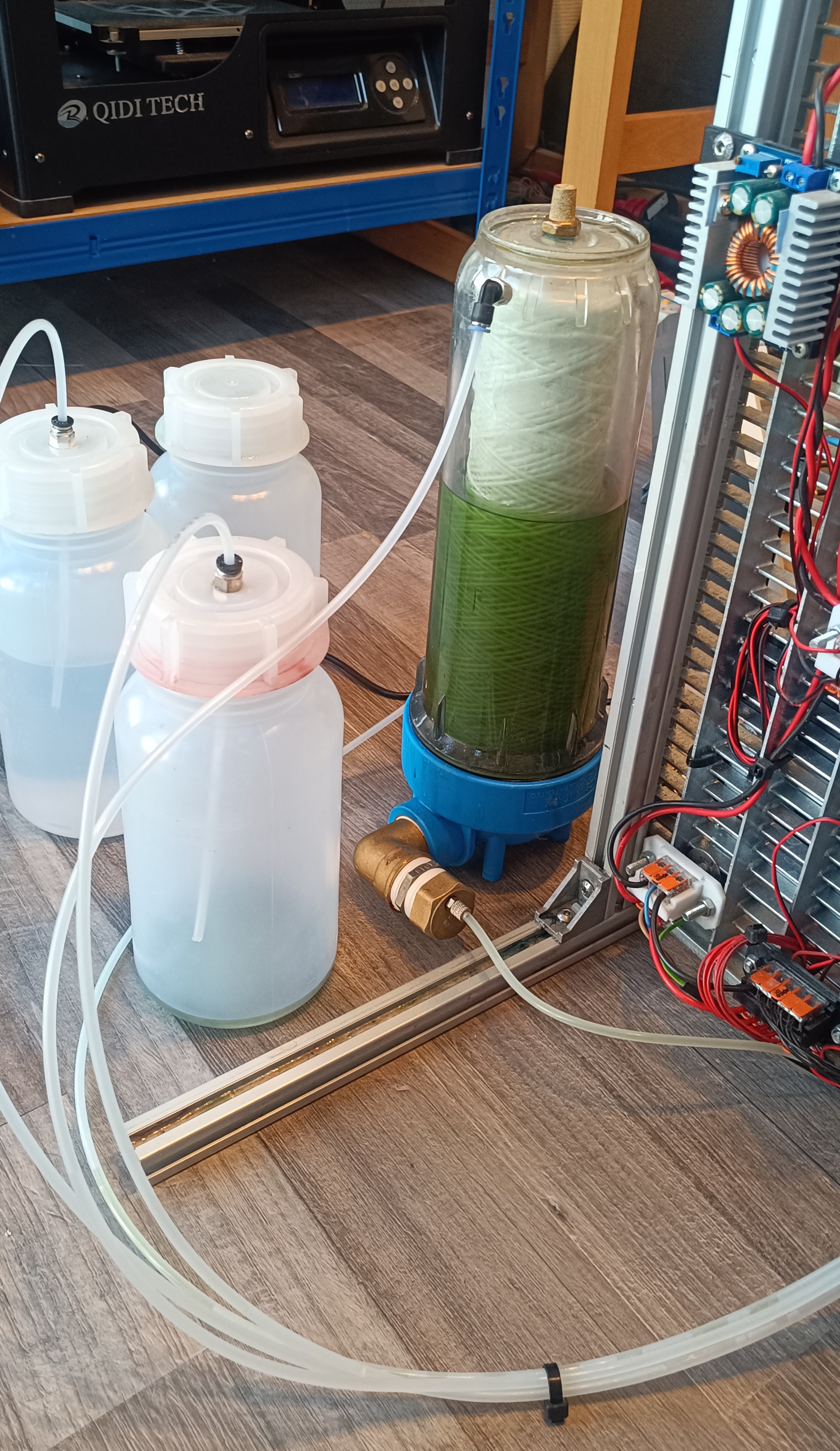
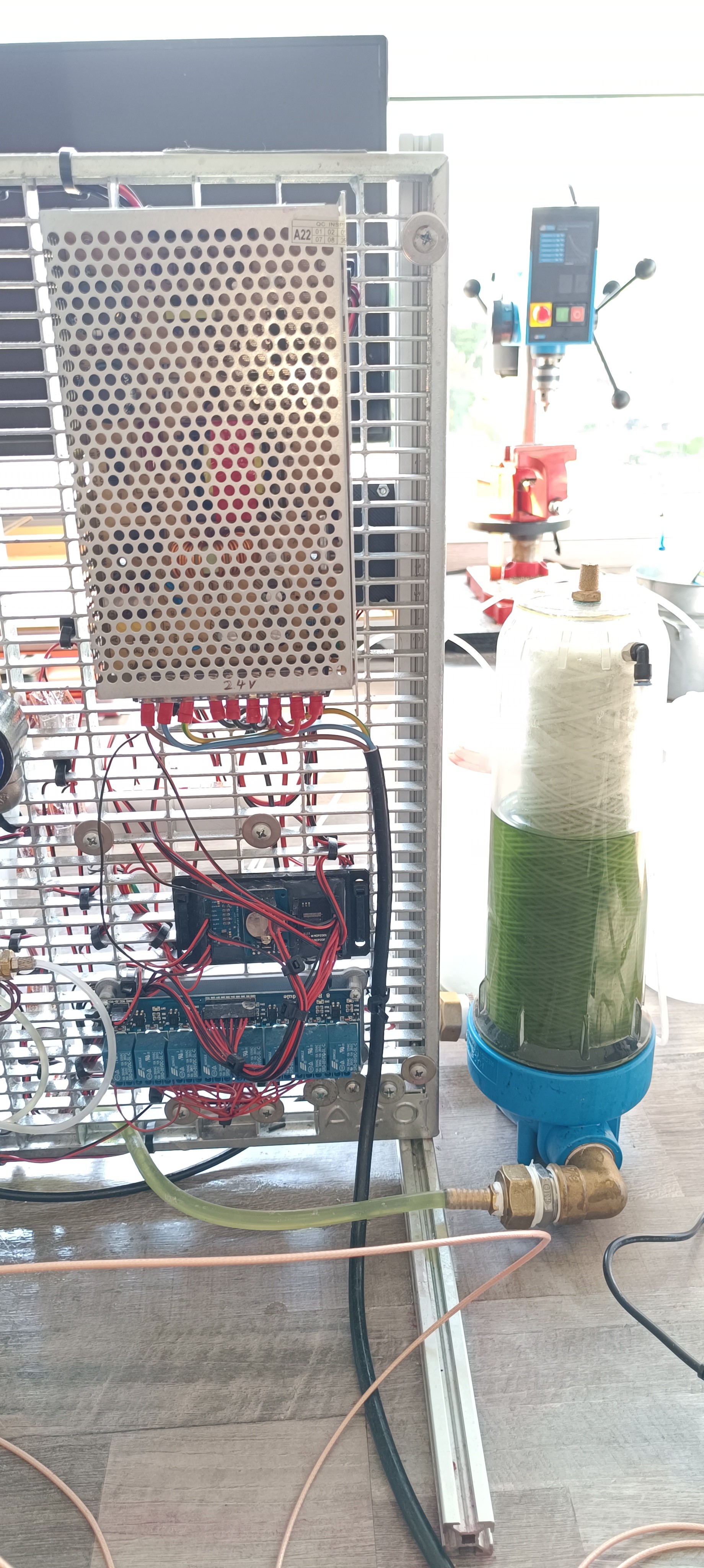
External Pressure Pumps
Another problem that I wanted to solve for a long time was that the pressure pumps were located outside the printer frame. I used four small pumps instead of one large pump because when used as intended, they are only allowed to run for two minutes until they need a one-minute break to prevent overheating.
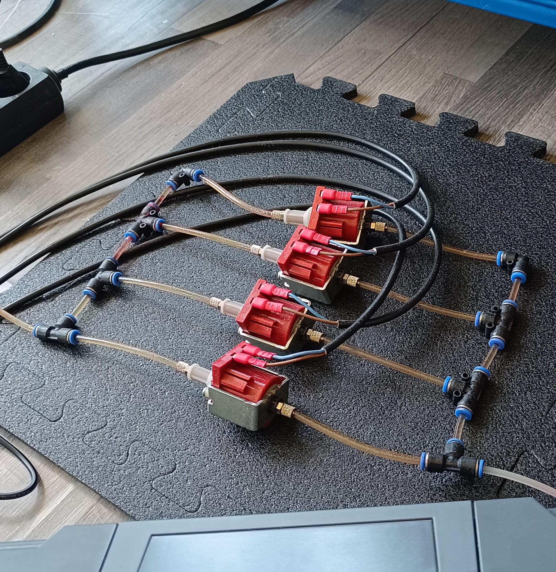
To solve this, I decided to use one large 24V vibratory pump and run it on a lower-duty cycle while cooling it with a small fan.
The pump I used for that is the ULKA EX5 24V, which is normally powered by AC. However, since these pumps already come with an integrated diode, they use only one half-wave of the AC cycle and can, therefore, be driven by pulsed DC without any problem. For driving it, I used the same BTS7960 H-Bridge that was used for driving the Peltier module before, because it was suitable for driving the pump, and I already had it wired to the printer controller and power.
I used a signal with 50Hz and a 30% duty cycle to drive the pump. To keep it cool, I used a 40*40*10mm 24V fan, and to not transfer the vibration to the printer frame, I used two short pieces of gt2 belt and some zip ties to let the pump hang from an angle bracket. In addition to that, I used a silicone tube for the inlet and an NBR tube for the outlet because the vibration of the pump was transferred through the PE tube I used before, which caused a lot of noise.
To protect the pump from overheating in case the pulse signal would freeze and expose the pump to DC for some time, I installed a bimetal switch that would interrupt the pump's power line in case of overheating.
After running the pump for some hours, it turned out that with the fan cooling it down, it only got slightly warm - far from overheating, which shows that continuous operation is possible with reduced duty cycle and air cooling.
Pressure Pump for Circulation
The pressure pump's outlet is connected to the fluid system to pressurize the ink pressure line.
When it first enters the system a relief valve is used to limit the pressure to 50 psi. The relief valve works by adjusting the flow from it back to the tank for keeping the pressure steady.
When I installed the new pressure pump, I realized that the relief valve's return path could be used for ink circulation on its own so that the peristaltic pump I installed before to replace the brushless pump could be removed.
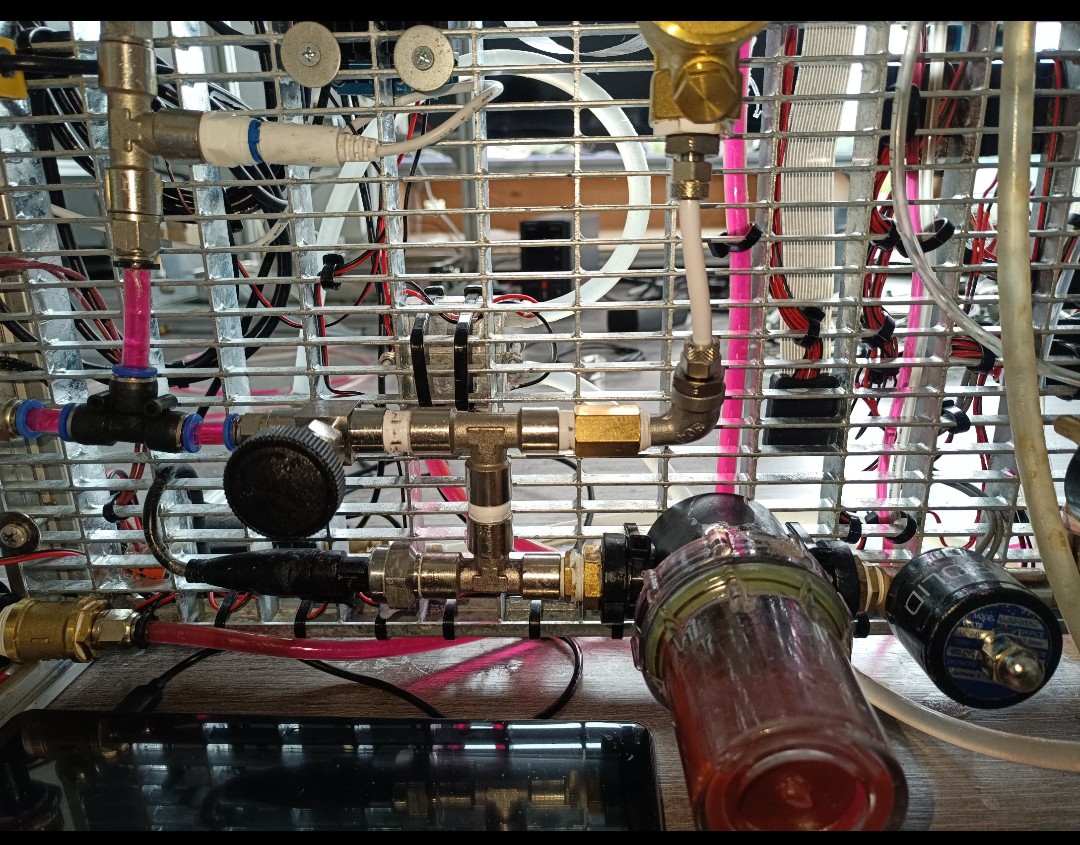
So, I changed the plumbing that the ink leaving the relief valve passes by the system temperature sensor and TDS sensor before flowing back into the tank. Now the line that leads back to the tank is located at the bottom of the frame instead at the top as it was before.
The return line is now a 4mm PE line instead of an 8mm PE line since the flow is lower than it was with the brushless pump. The NBR line from the pressure pump is a 7x3mm fuel line. The silicone tube that leads to the pressure pump had to be an 8mm tube because when the inlet flow to the pump is restricted, the pump wouldn't run properly and would make a lot of noise.
Individual groups of fittings are connected by an 8mm tube to give the connection a bit more stability.
My goal was to use a 4mm PE tube wherever I could and only use other tube diameters where it was absolutely necessary.
Maybe later on, with a more compact design, it would be possible to use even fewer tubes.
Here are a few pictures of the new plumbing:

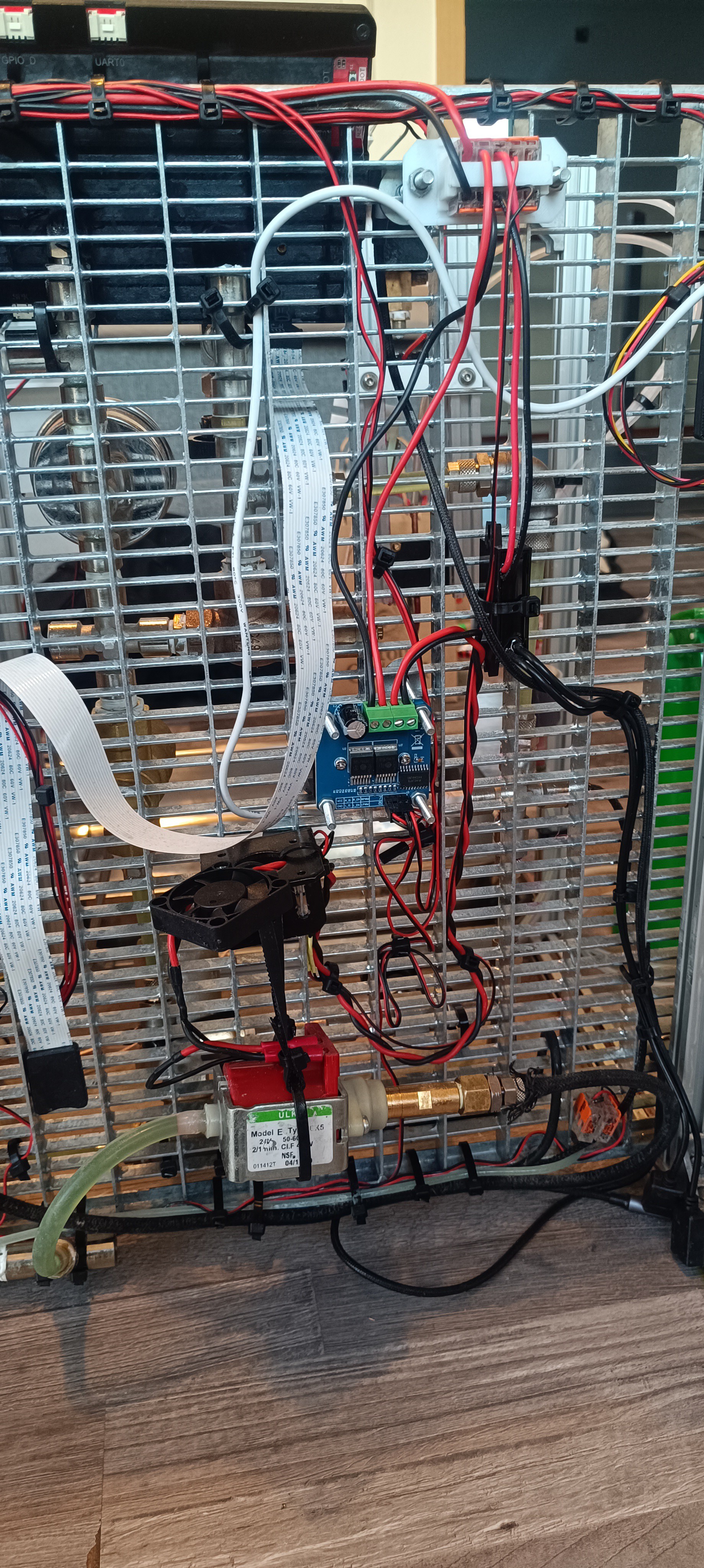
Here you can see how it looked before:

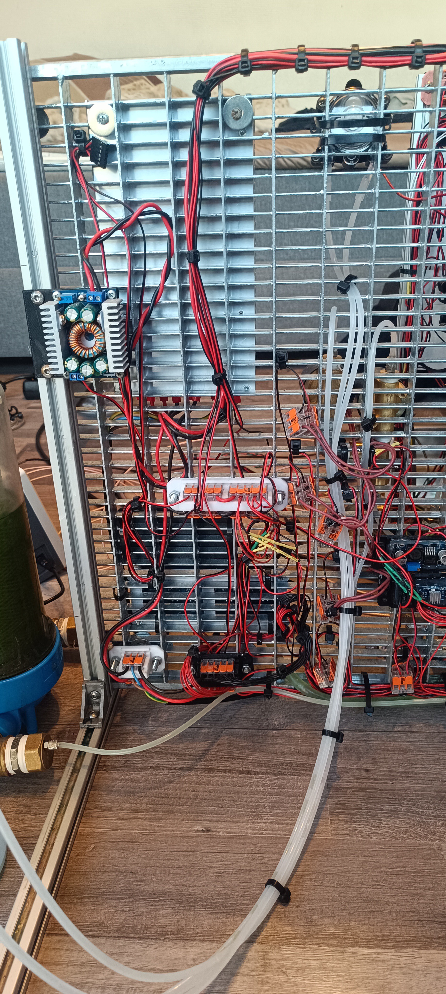
And here you can see how it looks now:

New Damper
When using the four external pressure pumps I also used an external damper. The damper acts like a capacitor in electrical circuits. It has a spring-loaded piston that pushes against the ink. When the ink pressure increases it tensions the spring. When the ink pressure decreases the piston pushes against the ink.
This helps stabilize the ink pressure and reduces the pulsation caused by the pressure pump.


The dampers are just off-the-shelf water hammer arrestors.
After removing the external pumps and damper, I got a new damper that I could connect to the position of the old filter, which actually also acted as some sort of damper with the air bubble inside of it getting compressed and expanding again.
With the new damper and new pump the only external parts of the fluid system were the ink tank and bottles, which will likely stay external in the future.

Updated UI
With the changes to the fluid system I also cleaned up the UI a bit.
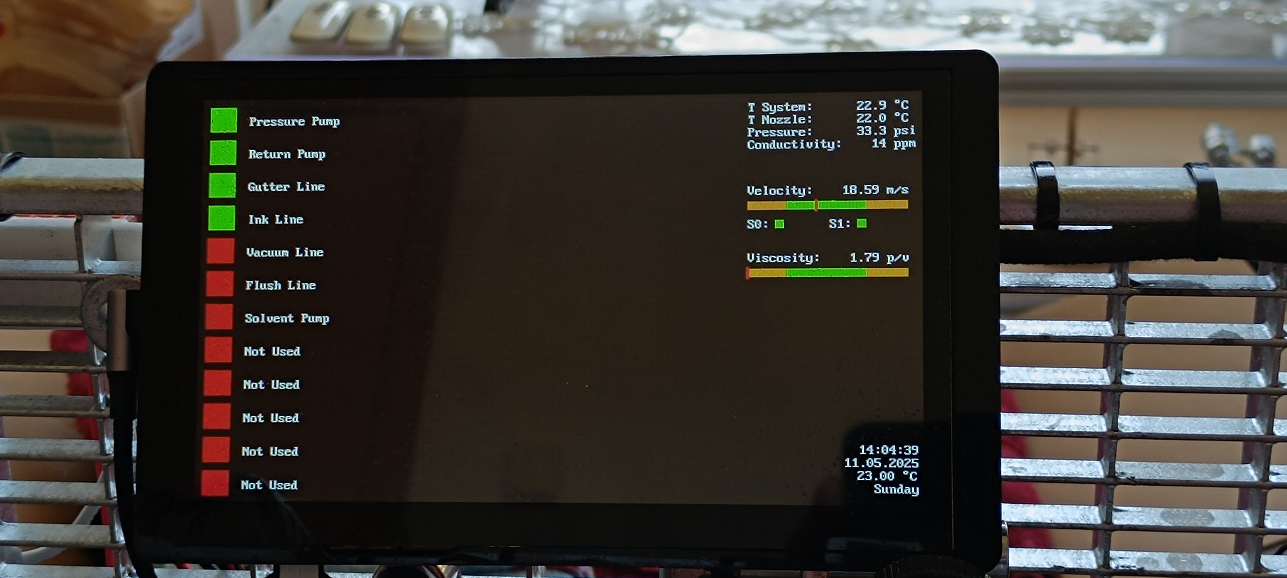
I think with these changes, cost and complexity got reduced a bit, and with a lower number of components, it should be possible to shrink down the design a bit in the future.
Discussions
Become a Hackaday.io Member
Create an account to leave a comment. Already have an account? Log In.