Maakbaas
-
GitHub
11/06/2021 at 06:02 • 0 commentsAfter publication on the front page, I got several requests for the design files. I have posted them to GitHub here:
https://github.com/maakbaas/esp32-soil-moisture-sensor/tree/master
-
Logging to the cloud
04/18/2021 at 18:04 • 0 commentsIn this final post I will dive into the connectivity and WiFi functions for the ESP32 soil moisture sensor. The goal is to be able to log the sensor data to the cloud and pull it into a home automation system. The data will first be buffered locally, and then pushed to the cloud in a batch. This is needed because WiFi is significantly more power hungry compared to other activity. With this approach the device should theoretically have a battery life of two years.
---------- more ----------
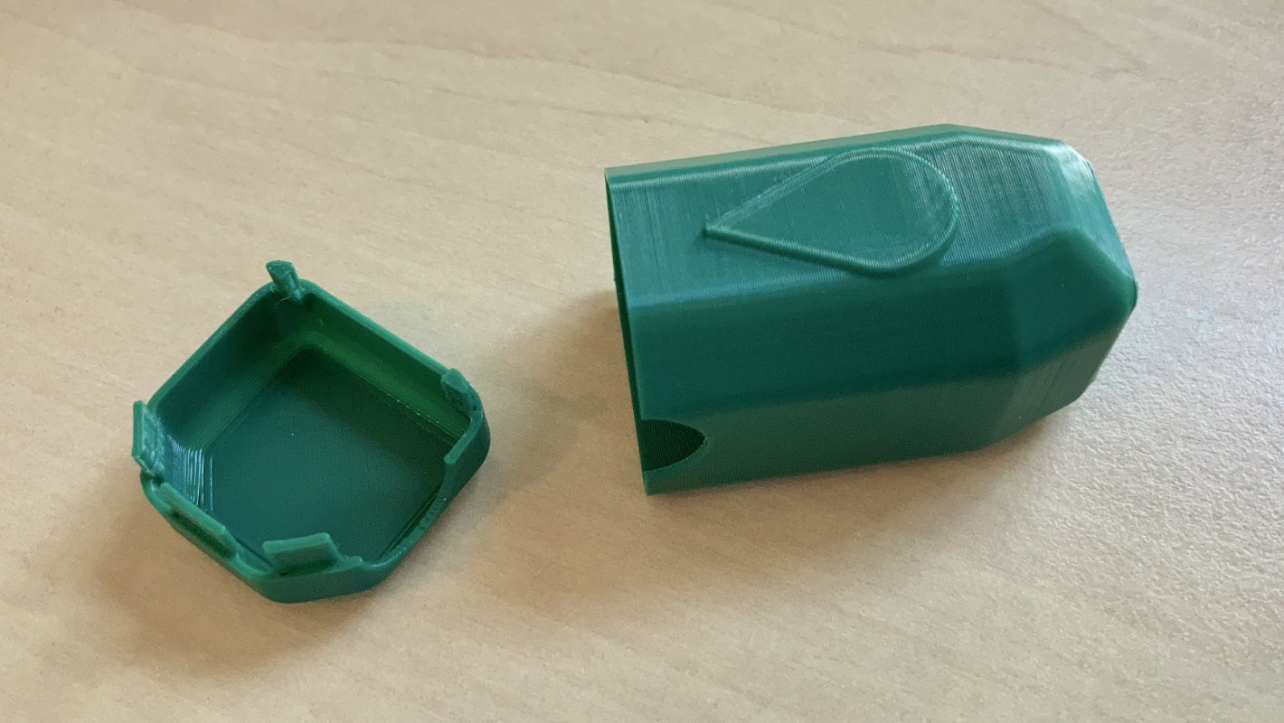
Before we dive into the software, a quick visual update. The PCB was still missing a case, so I designed one in Fusion 360 and printed it in garden green😉.![]()
![]()
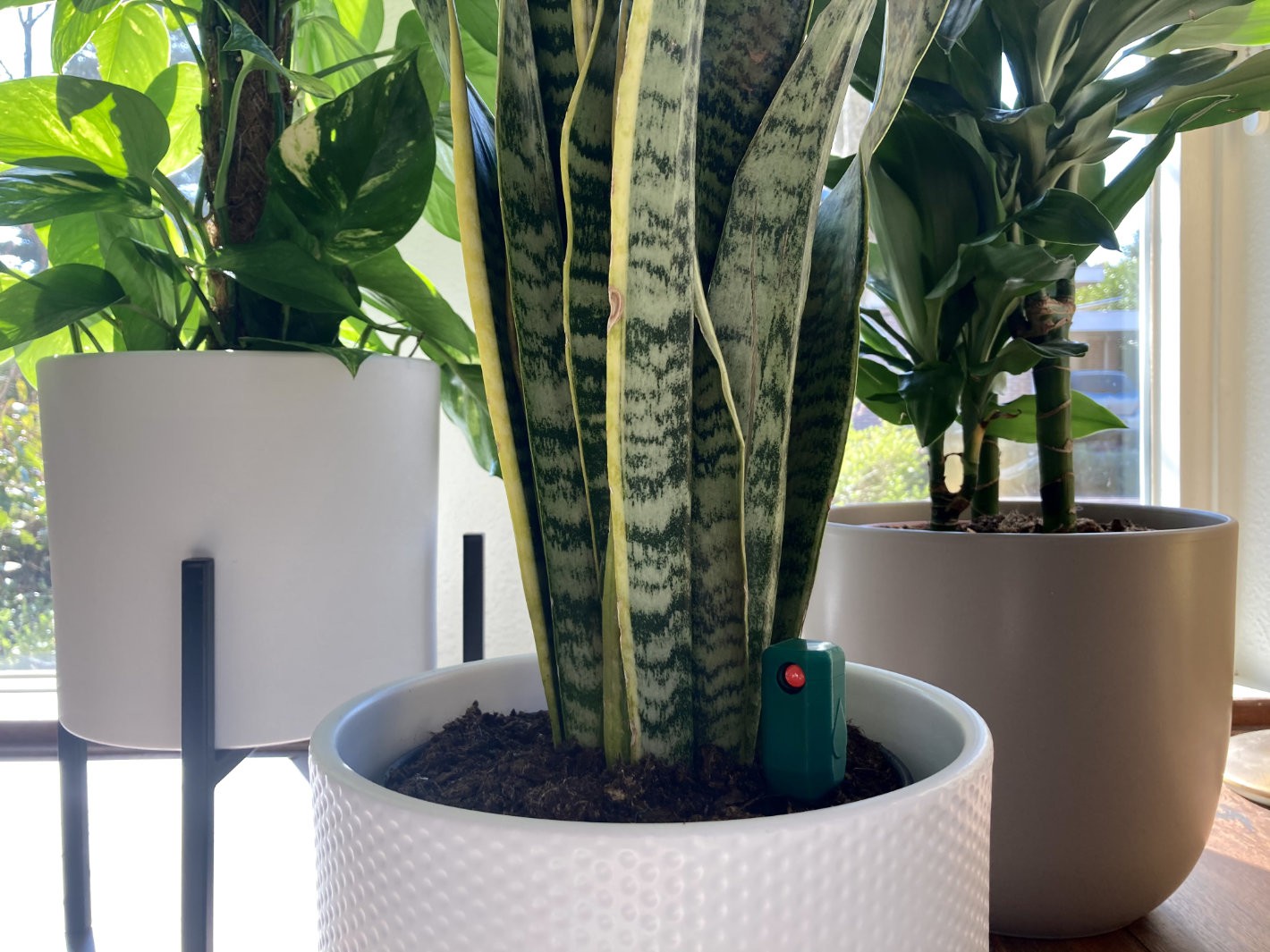
The 3D printed case and the final assembled sensor in action in our mini jungle.
Looking back at the battery calculations in the first post on this project, I assumed an hourly sensor reading and a daily push to the cloud. Logging more than hourly does not make sense given the slow dynamics of soil moisture levels. This means that the ESP32 must remember the last 24 sensor measurements locally in a buffer, and send them to the cloud periodically.
To be able to push historical timestamped data to the cloud I settled on using InfluxDB. It is quite easy to push a batch of data to the database with a single HTTP post request. It also helps that I already had an instance of InfluxDB running on my NAS 😉. But in any case this type of database is specifically designed for time series data, so it makes sense to use it for that purpose.
Connect to WiFi and NTP
During the first wake of the device, it will connect to WiFi and get the current time from a NTP server:
//Connect to WiFi
WiFi.mode(WIFI_STA);
WiFi.begin("SSID", "password");
while (WiFi.status() != WL_CONNECTED) {    delay(1000); }

//set real time clock
configTime(0, 0, "pool.ntp.org");   struct tm timeinfo;
getLocalTime(&timeinfo);
Filling the measurement buffer
Every hour the ESP32 is woken from deep sleep by the timer, the new sensor measurement is added to a buffer. There are three buffers. For the timestamp, the actual sensor value, and one for the threshold value, since it can be changed by the user by pressing the calibration button.
//write buffers
time_t now;
time(&now);
timestampBuffer[bufferIndex] = now;
thresholdBuffer[bufferIndex] = threshold;
measBuffer[bufferIndex] = output;
bufferIndex++;
Writing to InfluxDB
Once the buffer is full (after 24 measurements), the complete content is written to the InfluxDB database. However, there is one additional situation that triggers a write. This is when the sensor value crosses the threshold. This means the plant needs to be watered, and we don't want to wait for up to 23 hours to push this information to the cloud. Therefore this will also trigger a write to the database.
//write to DB daily or when watering is needed
if (bufferIndex == 24 || (output > threshold && status!=RED))
{
    initWiFi();
    HTTPClient http;
    http.begin("http://192.168.1.90:8086/write?db=plant&u=username&p=pass");    http.addHeader("Content-Type", "application/binary");

    char payload[2000], *pos = payload;
    for(int i=0; i<bufferIndex; i++)
    {
        pos += sprintf(pos,"moisture level=%d,threshold=%d %d000000000\n",
                       measBuffer[i],thresholdBuffer[i],timestampBuffer[i]);
    }

    http.POST((uint8_t *)payload, strlen(payload));
    http.end();

    bufferIndex=0;
}
In the for loop a char array is filled with the payload of the Post request. This is in what is called the InfluxDB line protocol, which is an intuitive way to format your data. After the data is sent to the database, bufferIndex is reset to zero to start filling the buffer for a new cycle.
Connecting to Home Assistant
The main reason I did not push the data to home assistant directly is that I did not find a way to push historical timestamped data, but of course the fact that the data is now in a database is not enough. It would be nice to integrate this with other measurements around the house, and to set up automations such that a low moisture level can trigger notifications. This is all possible with home assistant, so therefore we need to pull the InfluxDB data into home assistant.
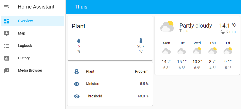
sensor:
  - platform: influxdb
    host: 192.168.1.90
    username: username
    password: pass
    queries:
    - name: Moisture
      value_template: '{{ (100 - float(value) / 11) | round(1)}}'
      unit_of_measurement: '%'
      group_function: last
      where: '"time" > 0'
      measurement: 'moisture'
      field: level
      database: plant
    - name: Threshold
      value_template: '{{ (100 - float(value) / 11) | round(1)}}'
      unit_of_measurement: '%'
      group_function: last
      where: '"time" > 0'
      measurement: 'moisture'
      field: threshold
      database: plant
}
By adding this code to configuration.yaml it is possible to use InfluxDB as a sensor source, and pull in both the actual moisture level and the user defined critical threshold. The value_template fields are used to transform the sensor reading (where 0 is very wet and 1100 is the maximum value in open air) into a moisture percentage between 0 and 100%.
![]()
The plant showing up in home assistant, it is thirsty!
That's it! Thanks for following along for this project.
-
Using deep sleep
04/16/2021 at 19:39 • 0 commentsIn this post and the next I will present the software that is running on my ESP32 soil moisture sensor. In this initial version of the software I focus on the parts that allow the sensor to work in standalone mode. This includes the push button, the status indicator and the actual sensor implementation. In the next and final post I will dive into the connectivity and WiFi functions.
---------- more ----------
The functions that the ESP32 soil moisture sensor should have are:- Perform a capacitive measurement of the soil moisture level
- Periodically wake from deep sleep and check if the moisture level is above the threshold
- Flip the status indicator to red if the moisture level is too low and to green if the level is above the threshold
- Wake from deep sleep with push button to set the current moisture level as the new threshold
- Push the measurements to a database in the cloud using WiFi
- Create a smartphone notification when the plant needs water
The last two items will be implemented in the next post. The rest will be discussed below.
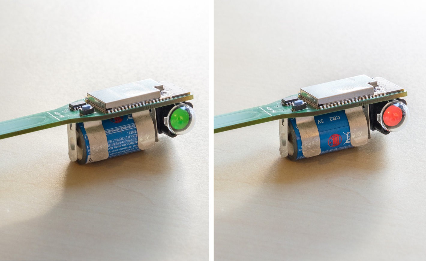
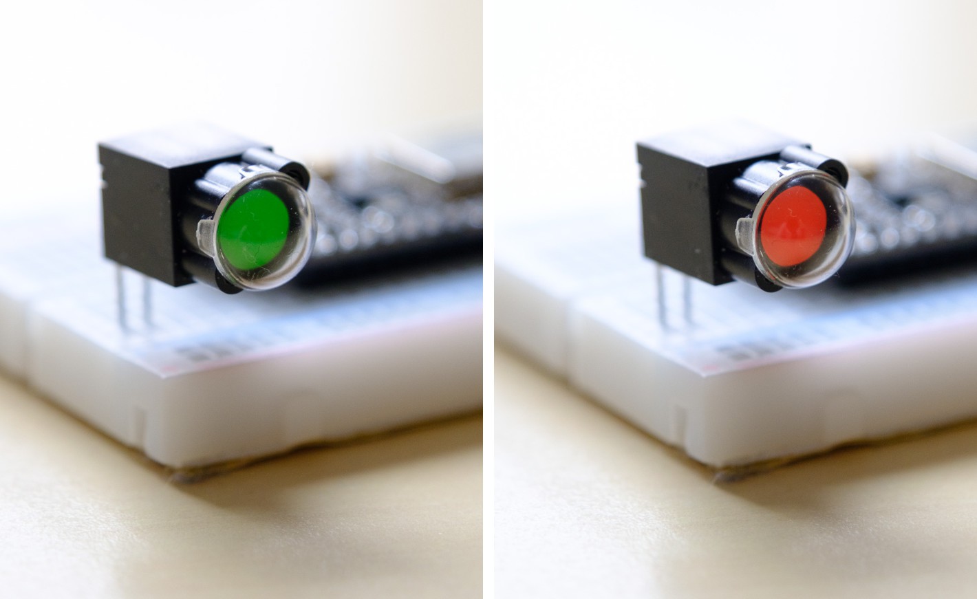
![]()
The two states of the status indicator.
Walking through the code
The basic principle of the code is that the ESP32 walks through a certain function once, and then goes to sleep again until the next wake event. Since I used the Arduino framework for this simple program, that means that all code is placed in the setup() function while the loop() function will remain empty.
The main architecture containing the deep sleep functionality is actually pretty simple and looks as follows:
#include <Arduino.h>
#include <Preferences.h>

Preferences preferences;

enum status_e{UNKNOWN, RED, GREEN};
RTC_DATA_ATTR uint16_t threshold = 0;
RTC_DATA_ATTR enum status_e status;
uint16_t output;

void setup() {
    // put your setup code here, to run once:
    pinMode(GPIO_NUM_13,OUTPUT);
    pinMode(GPIO_NUM_27,OUTPUT);
    pinMode(GPIO_NUM_26,INPUT_PULLUP);
    Serial.begin(115200);

    // perform a soil measurement
    do_measurement();

    esp_sleep_wakeup_cause_t wakeup_reason;
    wakeup_reason = esp_sleep_get_wakeup_cause();

    switch(wakeup_reason)
    {
        case ESP_SLEEP_WAKEUP_EXT0 :
            handle_buttonpress();
            break;
        case ESP_SLEEP_WAKEUP_TIMER :
            handle_timer();
            break;
        default :
            handle_firstwake();
            break;
    }

    esp_sleep_enable_ext0_wakeup(GPIO_NUM_26, 0);
    esp_sleep_enable_timer_wakeup(1000000 * 60 * 60);

    esp_deep_sleep_start();
}

void loop() {}
In the setup function, first the GPIO are configured. Pin 13 drives the H-bridge to switch the status indicator to red, pin 27 to green, and pin 26 is the push button. For this the internal pullup of the ESP32 is used.
Next, the function esp_sleep_get_wakeup_cause is used to determine what caused the ESP32 to wake up. There are three possibilities which are detected in a switch statement. The three possibilities are:
- Wake up from deep sleep by pushing the button
- Wake up from deep sleep because of the timer
- First startup of the device
These functions will be discussed in the next sections. Finally the deep sleep function is set up to wake from the button or by means of a timer.
do_measurement()
Reading the sensor using the ESP32 touch functions happens here as was already discussed in the previous post:
touch_pad_init();
touch_pad_set_voltage(TOUCH_HVOLT_2V4, TOUCH_LVOLT_0V5, TOUCH_HVOLT_ATTEN_1V);
touch_pad_config(TOUCH_PAD_NUM2, 0);

//do measurement
touch_pad_read(TOUCH_PAD_NUM2,&output);
handle_buttonpress()
When the button is pressed first a delay is placed to debounce the button. Otherwise the function might complete and retrigger multiple times before the button is released. After this, the threshold is updated with the current sensor value output subtracted by 5 to have some margin. The new threshold is stored into NVM by using the ESP32 preferences functions. Finally the status indicator is switched to red if it was not yet red before.
//debounce button press
delay(1000);

//set threshold to current value
threshold = output - 5;
preferences.begin("nvm", false);
preferences.putUShort("threshold",threshold);
preferences.end();

if (status!=RED)
{
    //set to red
    digitalWrite(GPIO_NUM_13,HIGH);
    delay(500);
    digitalWrite(GPIO_NUM_13,LOW);
}
handle_timer()
The timer function is even simpler. All it does is switch the status indicator where needed based on the current sensor reading.
//check the sensor
if (output > threshold && status!=RED)
{
    //set to red
    digitalWrite(GPIO_NUM_13,HIGH);
    delay(500);
    digitalWrite(GPIO_NUM_13,LOW);
} else if (output <= threshold && status!=GREEN)  {
    //set to green
    digitalWrite(GPIO_NUM_27,HIGH);
    delay(500);
    digitalWrite(GPIO_NUM_27,LOW);
}
handle_firstwake()
The final function handles initialization when the device is first powered on. In this case the status indicator is not changed, because it is quite likely that the device is not placed in the soil when it is first powered on. During this first initialization the threshold is read from the NVM and stored in a local variable. This local variable has theRTC_DATA_ATTR attribute, which means that it will be stored in such a way that it is persistent during deep sleep. This is not the case for normal memory.
//read EEPROM
preferences.begin("nvm", true);
threshold = preferences.getUShort("threshold");
preferences.end();
Next steps
In the next and final post I will present the connectivity and WiFi functions for this device which will enable it to push measurements and notifications to the cloud.
-
Testing the sensor
04/14/2021 at 20:25 • 0 commentsAfter receiving the circuit boards for my soil moisture sensor, the biggest question was whether the actual sensor would work. It seems like dark magic, how a simple copper pad, connected to an ESP32 without any additional circuitry could turn into a moisture sensor. Therefore, the first thing I did after building the boards is to see how well this would work.
---------- more ----------
Before diving into that, lets see how the board turned out:![]()
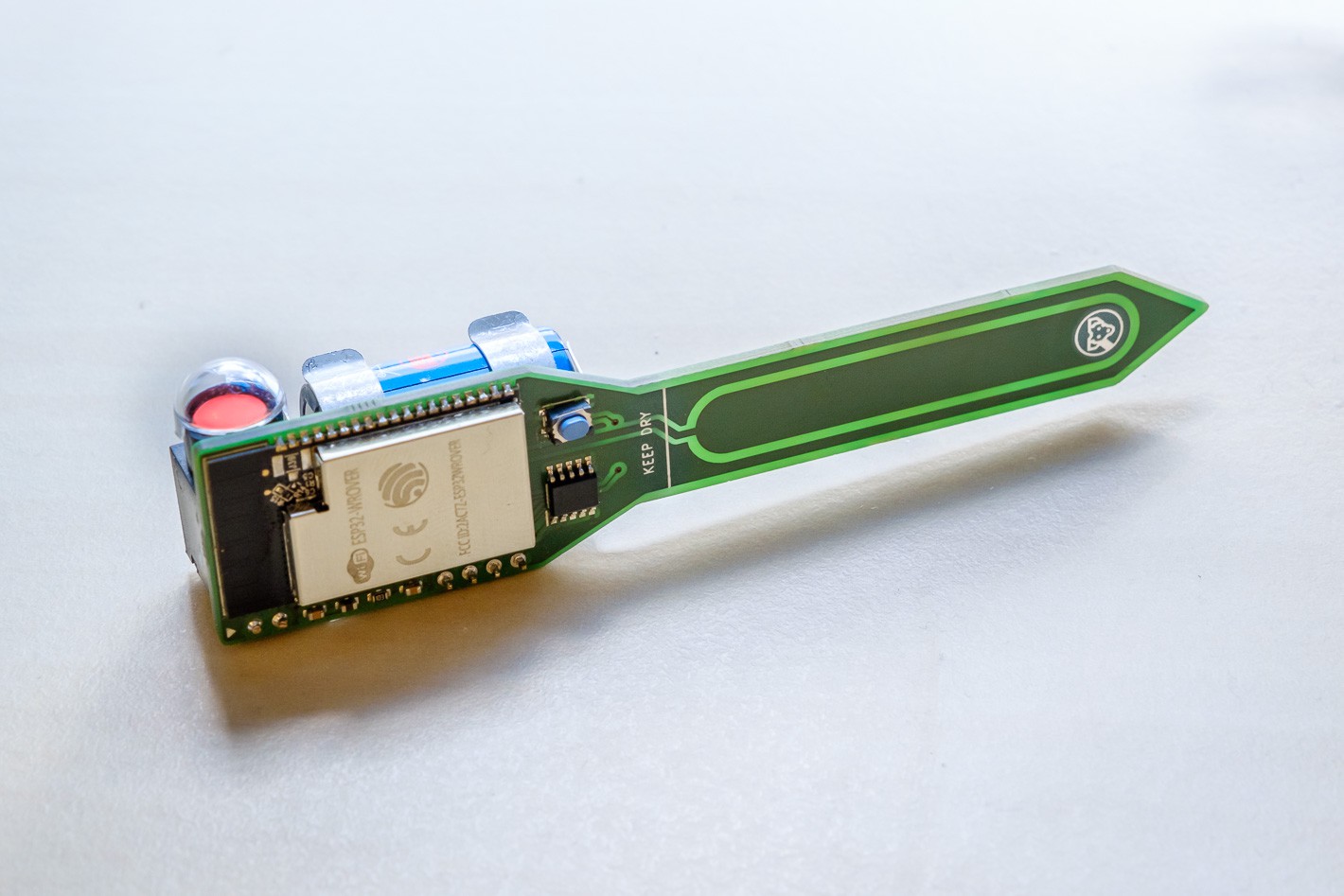
The finished board for the ESP32 soil moisture sensor.
The red dot on the left of the photo is a status indicator. This component can flip between green and red to show if the plant needs water and only uses current when switching between states. Pretty cool if you ask me.
How capacitive measurements work
In order to take away the magic, lets look at how the touch GPIO of the ESP32 actually works, and what is going on behind the scenes. The large copper pad on my PCB has a certain capacitance that (hopefully) changes based on what is around it. Air, water or soil should all lead to a different capacitance of this pad. This is exactly the same for the case of a more typical touch sensor application. Just like water, your finger will increase the self capacitance of the copper pad, allowing the ESP32 to detect this as a touch.
![]()
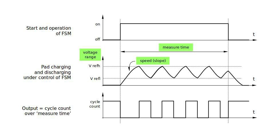
How the ESP32 measures capacitance.
Since capacitance can't be measured directly, the ESP32 uses a trick for this. As can be seen in the figure above, the ESP toggles the output of the touch pin until a certain voltage is reached, after that, the stimulus is removed and the voltage discharges again. The lower the capacitance, the quicker this cycle.
During a predefined period of time, the ESP32 keeps toggling the pad, and the more cycles it can perform during this period, the lower the capacitance. Therefore, what we should see is a decrease in the touch GPIO output when the amount of water increases.
Reading the touch sensor
First I tested the sensor using the touchRead Arduino function. With this I saw an output of around 60 when the sensor was in open air, and close to zero when touching the pad. Success! At least the sensor is doing something! However, 60 as a maximum output was not the granularity I had hoped for. Therefore I switched to using the ESP-IDF functions where more setup is possible:
//one time initialization
touch_pad_init();
touch_pad_set_voltage(TOUCH_HVOLT_2V4, TOUCH_LVOLT_0V5, TOUCH_HVOLT_ATTEN_1V);
touch_pad_config(TOUCH_PAD_NUM2, 0);

//read touch output
uint16_t output;
touch_pad_read(TOUCH_PAD_NUM2,&output);
Serial.println(output);
Initialize and read the touch pad using the ESP-IDF API.
With these functions, the maximum output in open air has increased to around 1000, giving the sensor a much higher sensitivity. With this I started my further testing with actual soil.
Testing and calibration
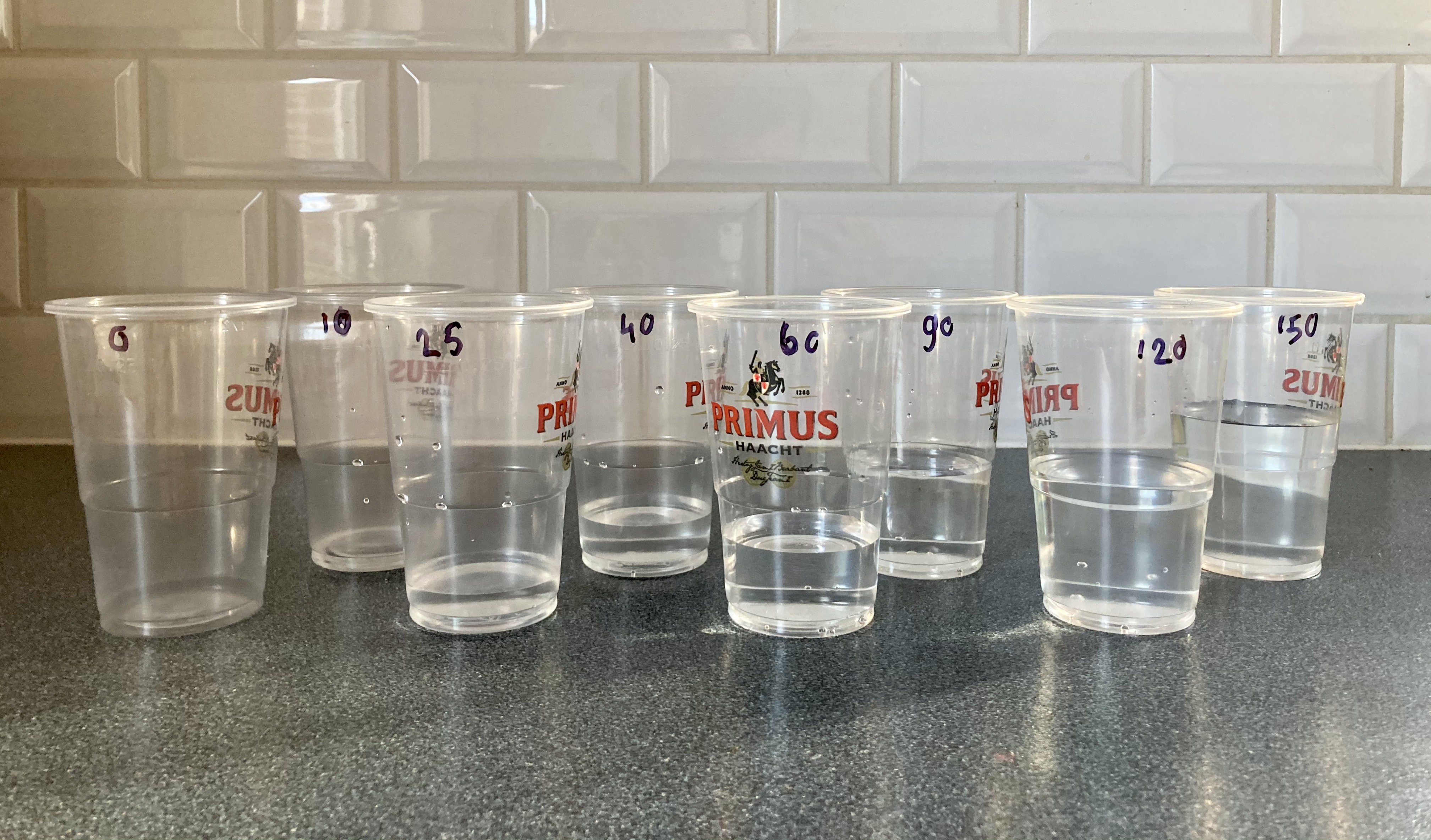
I created a set of cups with increasing amounts of water and mixed soil into it from dry to very, very wet.
![]()
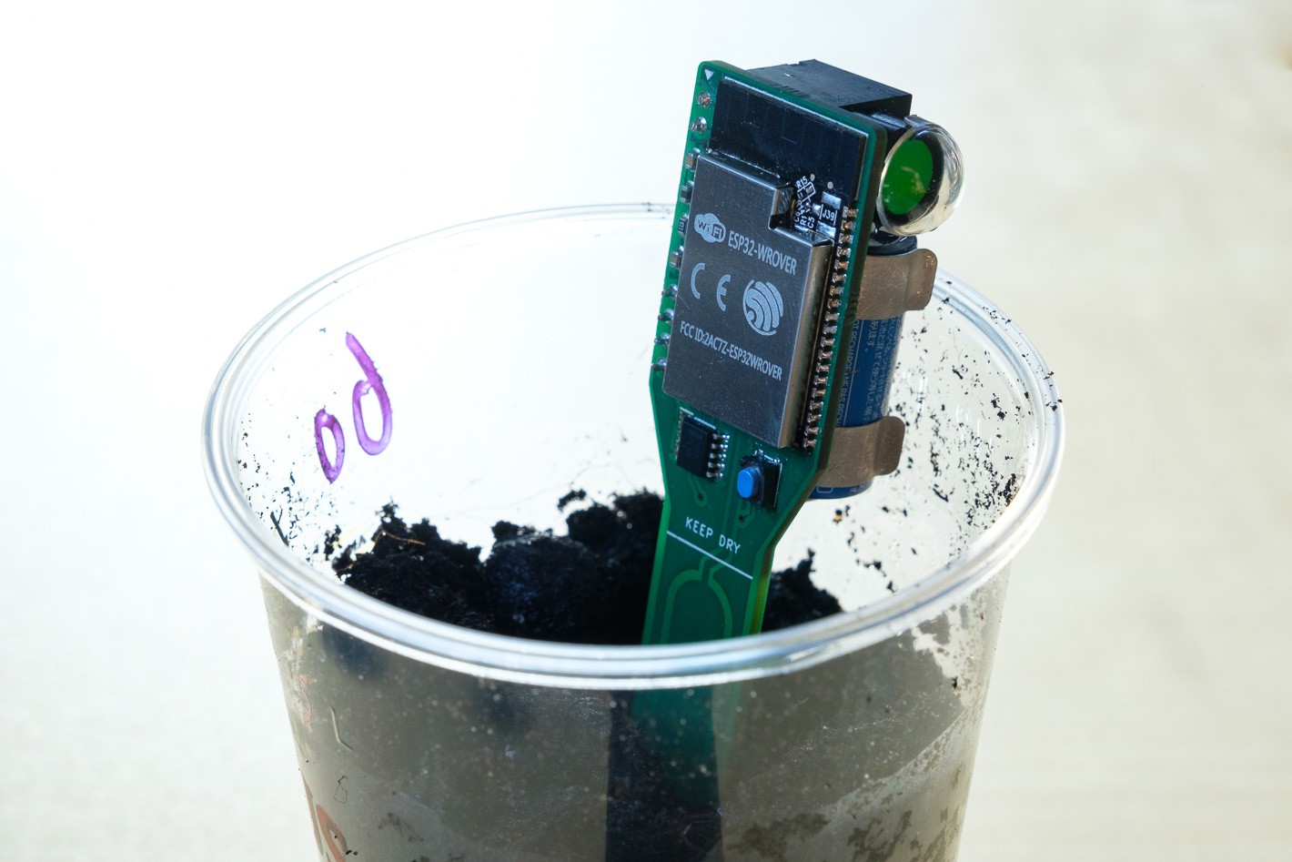
![]()
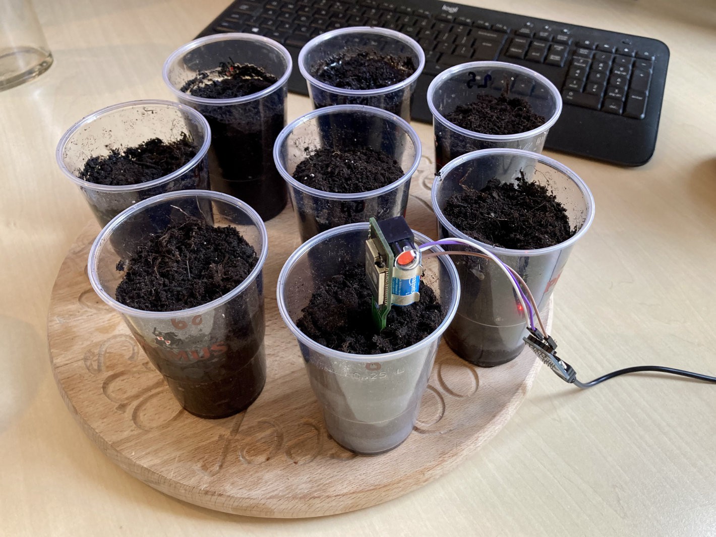
Testing the soil moisture sensor.
The results of this test were promising, but not good enough to be usable.
![]()
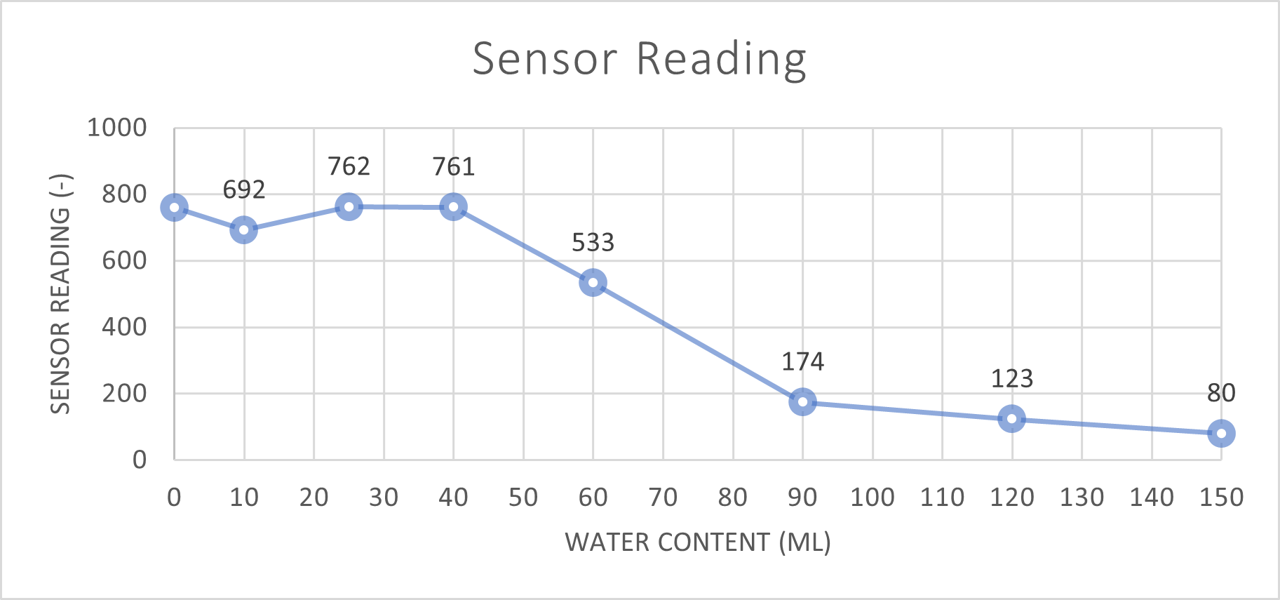
First results
Although this test clearly shows a decreasing capacitance with increasing water content, this is mainly for really wet soil. I asked my wife to fill one of the cups as if she was watering a plant (this goes to show I really need this sensor 😂), and this came out around 40ml. This means that the region between 0 and 40ml is the most important to measure.
There was however a major flaw in my test. I first put the water in the cup, and then the soil. Meaning that for lower water levels, most of the soil was dry, except for a small layer on the bottom, where my sensor did not even reach. After realizing this, I did the test again, but now watering the soil, just like you would do with a plant. I removed the really wet data points from the test, since they were not relevant.
![]()
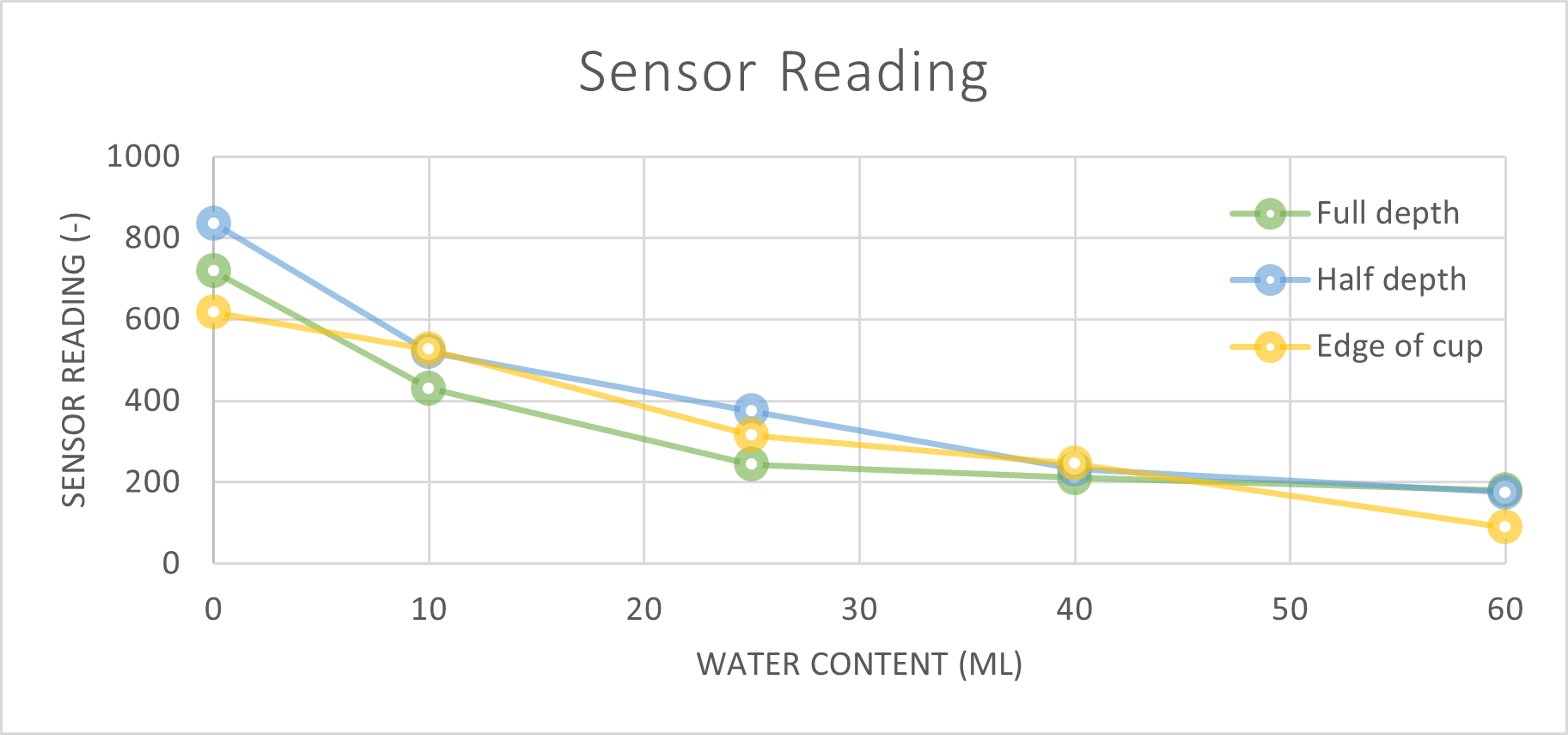
Results for different sensor positions
Luckily with this second test the results at lower moisture levels where much better. It can clearly be seen that the sensor reading decreases for water levels between 0 and 40ml. This means the sensor is definitely usable for its intended purpose!
I also tried placing the sensor at full and half depth, and close to the edge of the cup. As expected, this also causes variation, but the trends remain as it should. What this does mean however is that the threshold for a sensor needs to be set individually for each device. With this sensitivity to sensor placement a real absolute repeatable measurement is not feasible. This was in line with my expectations, which is why I also added a push button to the design that enables user calibration.
Next steps
In the next posts I will first implement deep sleep and all the software for the sensor to work in standalone mode. After that, the connectivity and WiFi functions will be presented.
![]()
The soil moisture sensor in action.
-
Hardware design
04/04/2021 at 14:19 • 0 commentsRecently we bought some new plants to fill up some of the space after we moved to a larger house. I am not the best plant owner, and need to be reminded when to water these new housemates. Roughly at the same time, I found a cool new component, that can switch from red to green, and only requires current when switching. This makes it a great status indicator for battery-powered products. One plus one is two, and this gave me the idea to build a soil moisuture sensor using this status indicator.
---------- more ----------
For this product I wanted to have the following features:- WiFi connectivity to log data to the cloud
- Visible status indicator on the PCB
- A button to allow for user inputs, like setting the baseline moisture level
- Low power, battery powered. Preferrably it should work for at least a year
- As small as possible given the other requirements
In the next sections I will discuss the status indicator, why I selected the ESP32, the battery selection and the sensing method.
Status indicator
As I mentioned, I found a cool status indicator, made by the company Alfa-Zeta. The unique thing about this component is that it only requires current to switch the color, but it does not require anything to hold the current color which makes it perfect for battery-powered applications. The idea will be to switch the color to red if a plant needs more water 😎.
![]()
The status indicator can switch between red and green.
The way this component works is by two small coils that flip a magnetic element up side down. According to the datasheet, the minimum voltage for this is 4.5V, but I found it even works on a single AA battery, which will come in handy as we will see later. That being said, the current during switching is higher than what can be provided from a GPIO pin. Therefore a H-bridge is needed to control this indicator from the microcontroller.
ESP8266 vs ESP32
My first idea was to use ESP8266, since it is of course powerful enough for this simple application. This is the first project where I want to run on batteries, and therefore also the deep sleep capabilities are important. I quickly found out that the ESP8266 is too limited in this area. While deep sleep is supported, it is not possible to clearly distinghuish between the following three cases:
- Power on
- Wake from deep sleep through timer
- Wake from deep sleep through button
Especially the last case is problematic. While it is possible to distinghuish in your code between the first two cases, the button press can't be separated. This brings some issues for the code because it is not straightforward to respond to a button press in a different way than to a normal wakeup event. This is why I chose the ESP32 which does not have this issue 👍.
Battery selection
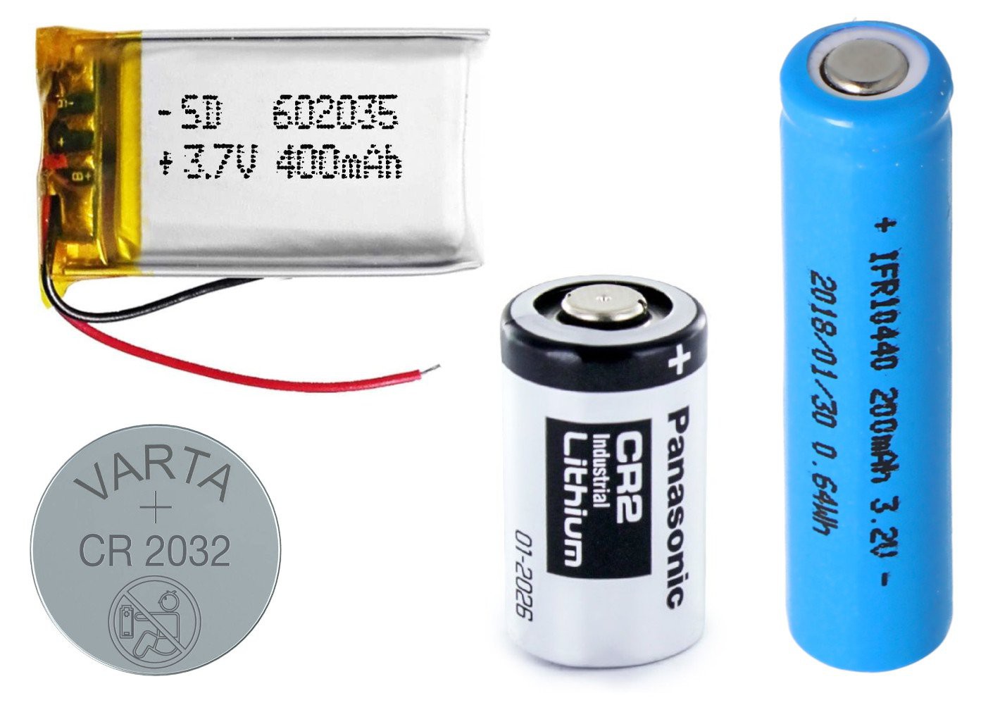
Since this was the first time designing something on batteries I considered four different options.
![]()
The four options I considered for the battery, with the correct relative scaling: CR2032, CR2, LifePo4 AAA and LiPo cell.
AAA LifePo4 cell (200MaH)
LifePo4 is a great chemistry for electronics projects. A fully charged cell is less than 3.6V and it stays above 3V for most of its capacity. This means you can use it with an ESP32 without the need for a voltage regulator. Drawbacks are the low power density and high price.
1s LiPo cell (400MaH)
LiPo cells are a very common battery because of their high power density. For me this option had two drawbacks. First of all the max cell voltage is 4.2V, meaning that a voltage regulator is a must. Secondly, because of the shape it is not possible to mount the battery directly to the board using SMD components.
CR2 battery (800MaH)
This battery has a high power density, and a form factor that fits wel into my design. The main drawback is that these batteries are not rechargable, and that the voltage is below 3V for most of its life, which is too low for the ESP32. However, there is exactly one ESP32 module, the ESP32-WROVER, which uses 1.8V flash memory instead of 3V. Because of this, this module works for voltages all the way down to 2.3V, and a CR2 battery can be used without a voltage regulator.
CR2032 coin cell (220MaH)
A coin cell would be awesome because of its size. The voltage is the same as for the CR2 battery. The main problem of the CR2032 is that the current needed for an ESP32 can't be provided. A workaround could be to add a capacitor that buffers enough energy to keep the device alive for a few seconds. However, this makes it awkward for debugging and development. Maybe it is something I will revisit in the future.
Battery life
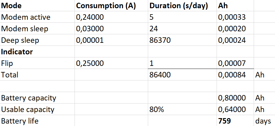
Considering these options, I have decided to use the CR2 battery in this product. By making some assumptions in the calculation below, the extimated battery life is around 2 years. I am sure that my calculations are too optimistic, but even so, I hope that one year of battery life should be within reach.
![]()
Excel calculation for battery life.
Sensing method
The sensor will use a large metal pad in the soil to do a capacitive measurement. This concept is used in other commercial sensors as well, such as the chirp, or the Adafruit Stemma. There are differences in the design of the actual pad though. The Stema does not have any shielding around or behind the pad, while the Chirp has both. For my design I decided to place a ground plane around the sensor, to shield it from disturbances, but no ground on the bottom layer in order to keep the sensitivity as high as possible.
After deciding to use the ESP32, I realised that it actually has touch GPIO inputs. Touch inputs are exactly that, a capacitive measurement on a metal pad. After some searching on Google I found that others have succesfully used this functionality for soil measurements as well, so that makes the board a lot simpler, since no additional sensor circuitry is needed.
Design and schematic
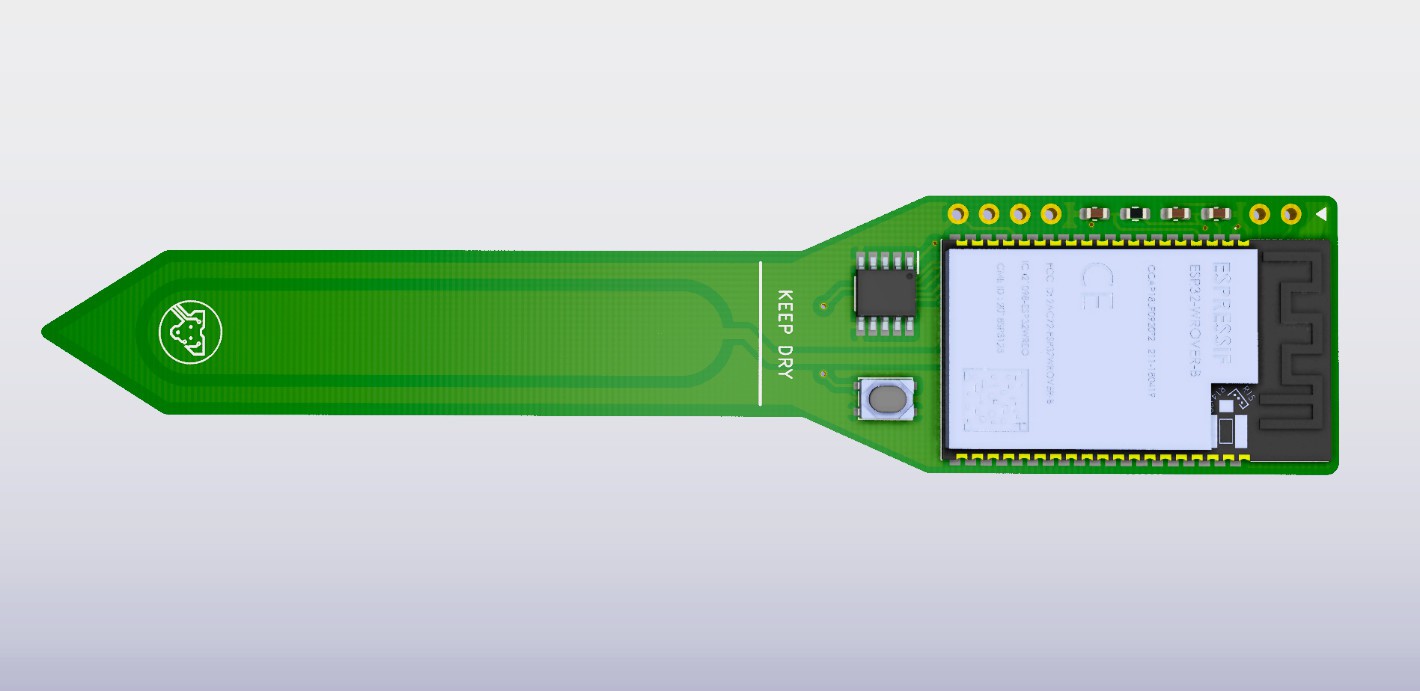
The final design and schematic for the PCB can be seen below.
![]()
PCB design. The status indicator and battery will be mounted on the back of the board.
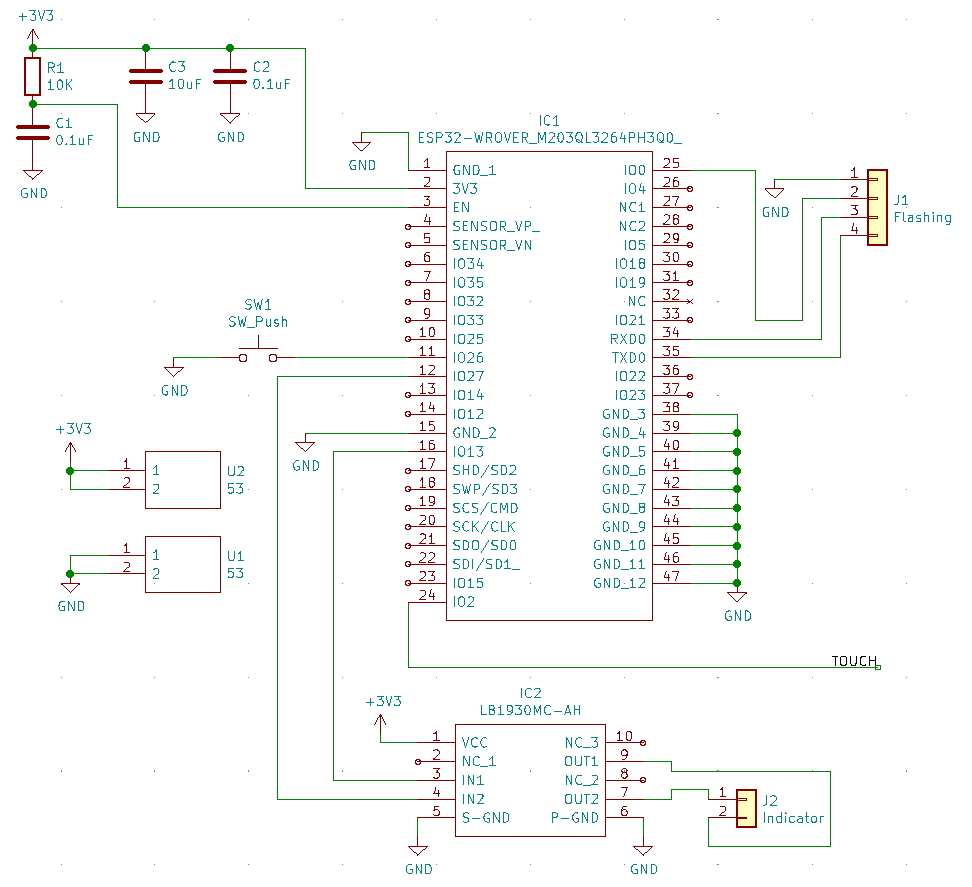
![]()
Schematic.
In the next post I aim to test and calibrate the sensor with some real water, soil and plants!
ESP32 Soil Moisture Sensor with Flip-Dot
In this project I develop a small, battery-powered soil moisture sensor using the ESP32 with a status indicator and logging to the cloud!