-
Solar Charger - Testing the prototype
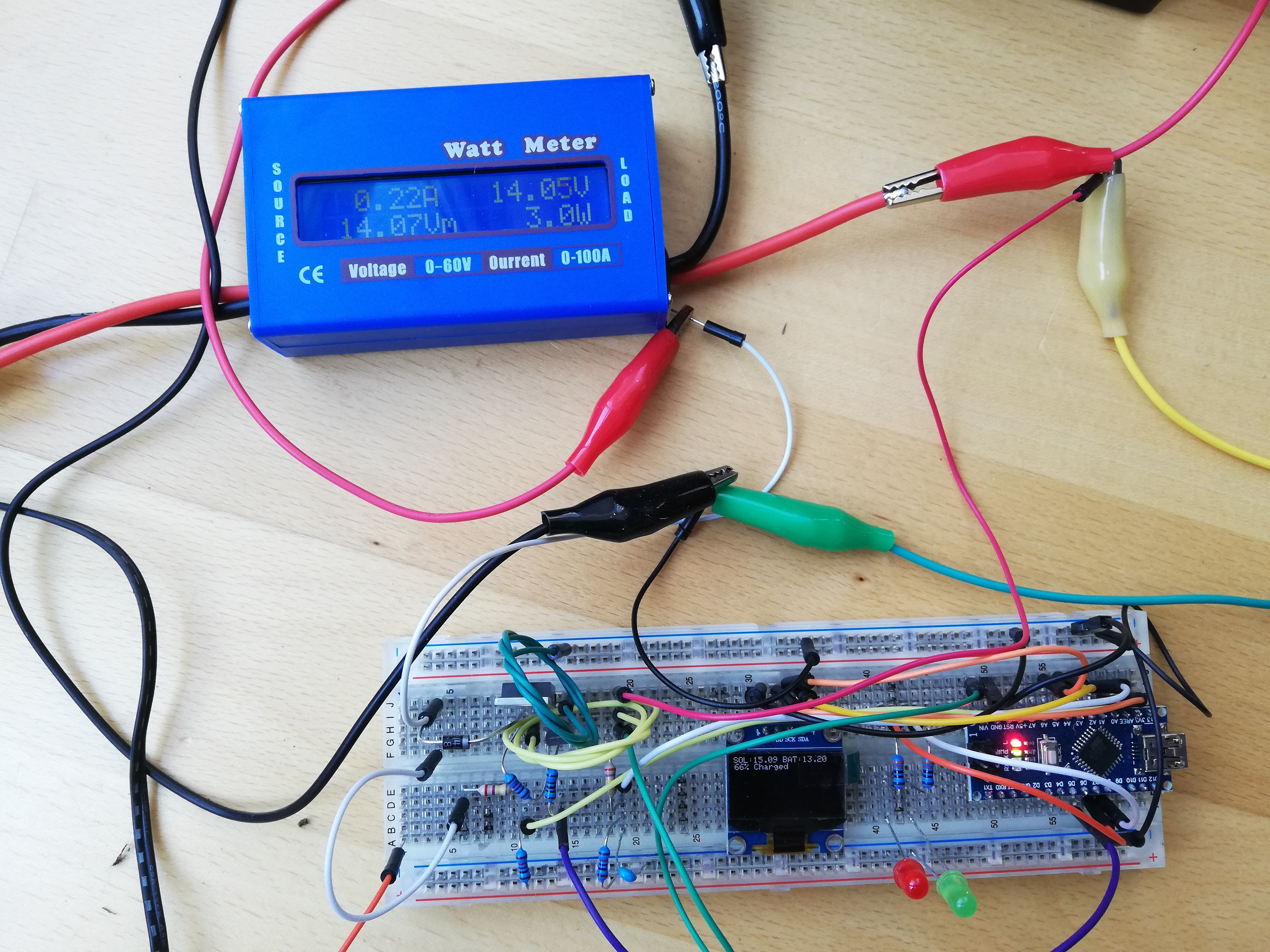
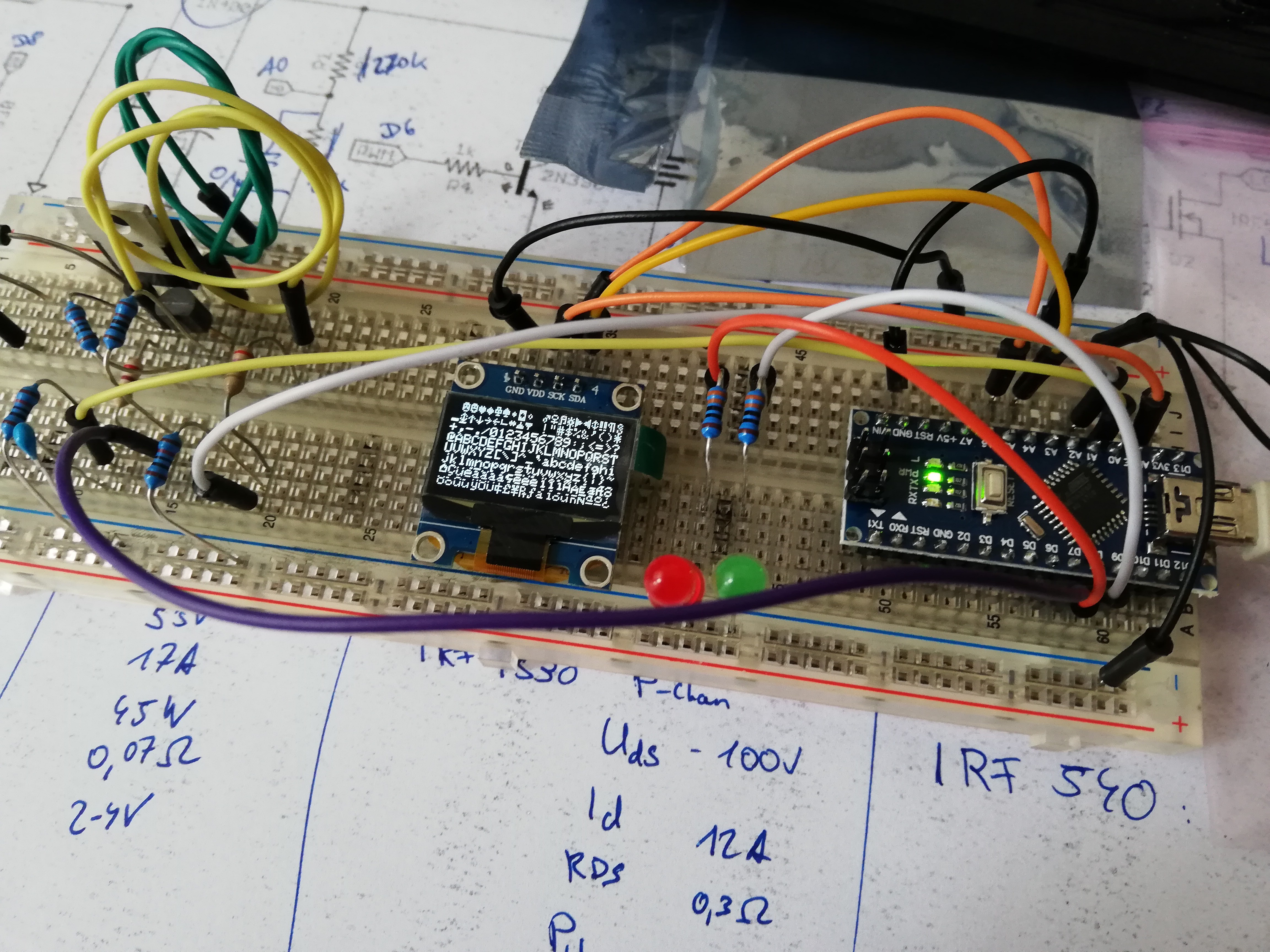
04/29/2021 at 10:12 • 0 commentsWhile the code is still in progress, and the prototype remains in its not-quite-there-yet breadboard form, I got one great piece of test gear: A watt meter. Basically a fancy multimeter thing that measures voltage and current, and calculates the amount of power passing though. I've been using it here to measure the power coming in from the solar panel, and on good days, I've been getting up to 4W into the solar charger prototype and the battery behind it.
![]()
There are a few things I realized while doing this:
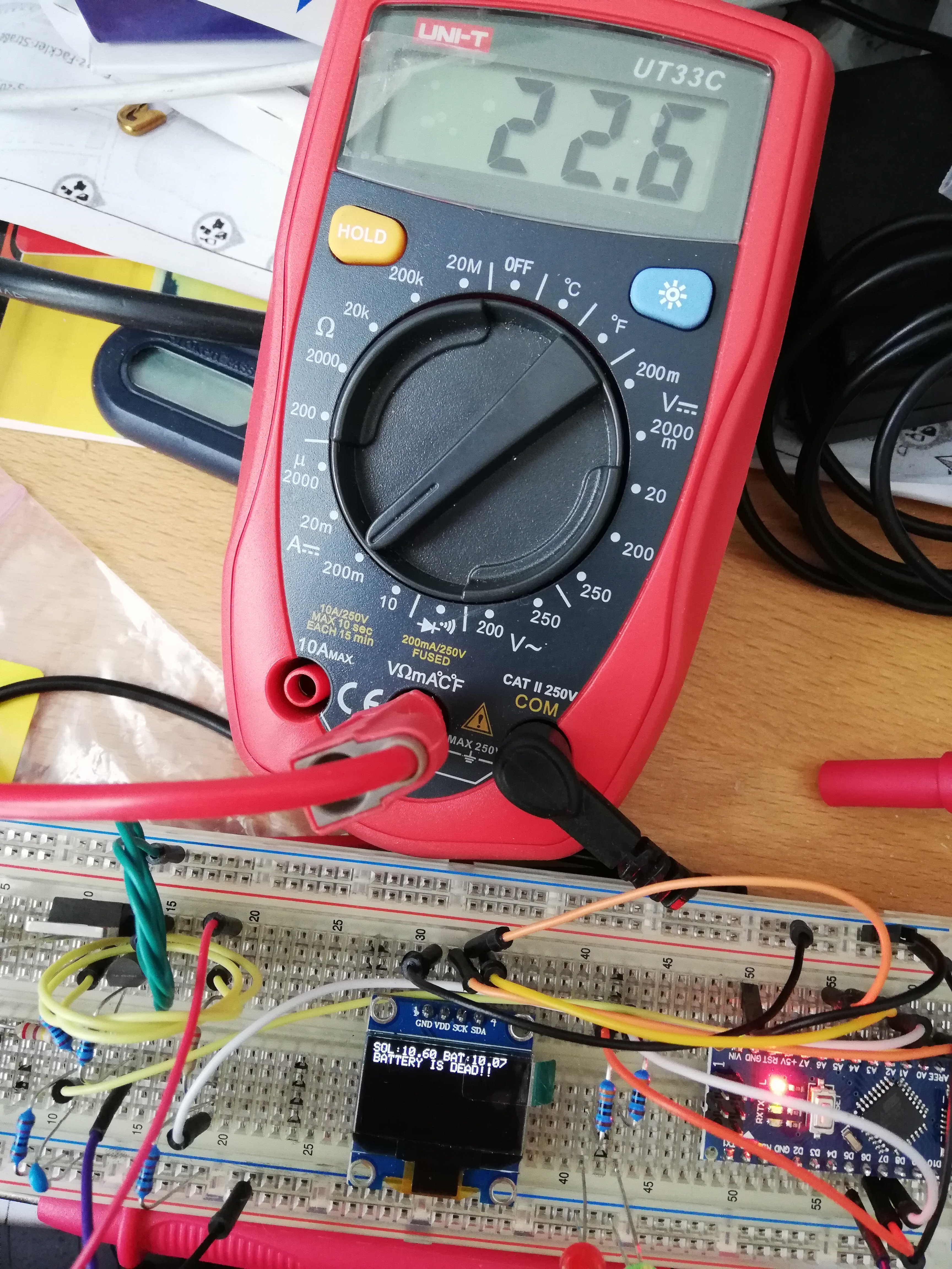
- While most of the time, voltage measurements on the watt meter and on the charger are reasonably close, sometimes they're quite a bit off. This is probably due to the not-so-great wiring job I've done on the breadboard. So one of the next things to do is really put this on protoboard. I do have to exchange some parts before that though, but that leads me to a second thing
- I'm missing a comparison. I have a chinese cheap-o solar charger, which I'm trying to at least come close to in terms of performance. But I can't actually compare them side-by-side, so I'll need a complete second setup (solar panel + battery) to actually do any comparisons.
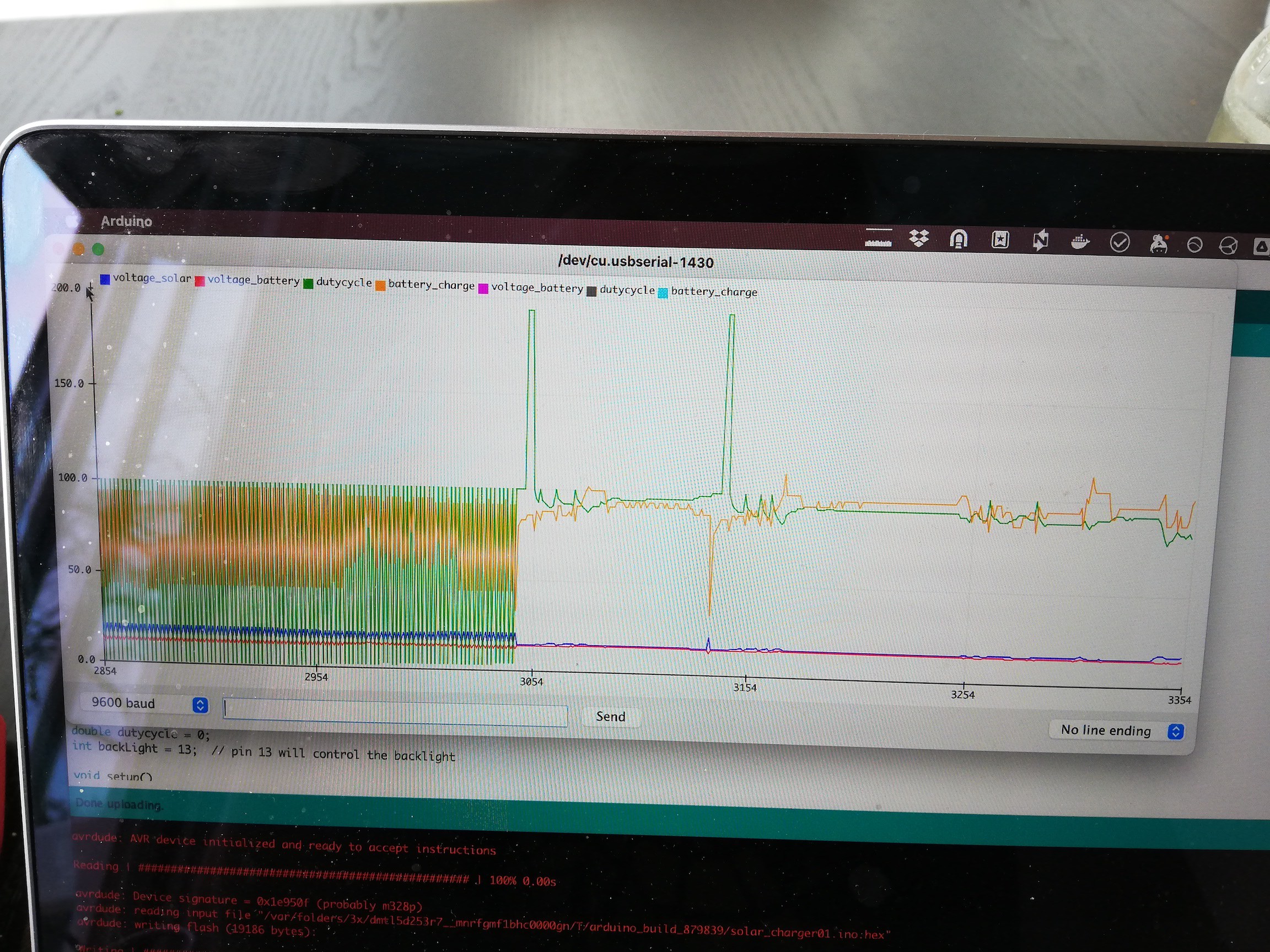
- When in full sun, the algorithm for controlling the charging MOSFET went all over the board again, despite the fixes I did last time. I looked at some other projects, and went back to a much simpler implementation again, which works so much better.
The next steps now are going to be:
- Finally find a place for the source code online
- Get a new solar panel
- Exchange some parts, add the load MOSFET, test it on the breadboard and then build it on protoboard for more solid connections
However, there's another project that'll need my attention in the meantime, so looks like this will have to wait for a week or three.
-
Solar Charger - First Prototype
04/14/2021 at 21:58 • 0 commentsAfter digging through more and more parts bags, I finally found 2 P-channel MOSFETs, so I can actually start prototyping the circuit for the solar charger. The instructable the charger is based on uses a normal 16x2 LCD, but that's too bulky for the lamp. I instead wanted to use a much smaller OLED screen, controlled via I2C.
![]()
The particular display I have seems to use a non-standard I2C address, so it wouldn't show anything at all at first. Luckily, there's an example in the Arduino IDE which can scan the I2C bus for devices and show their addresses, so this was not too troubling.
The Arduino libraries for the 16x2 LCD and the OLED seemed mostly compatible, so this was a fairly easy replacement. One interesting issue is that the "setCursor" function of the LCD library thinks in lines, while the OLED library thinks in pixels, so instead of printing something to the second line, I initially wrote the second line almost completely above the first, offset only by a single pixel. This as a bit irritating and took me a second to figure out, but the fix was quite easy, just multiplying line values by 8, column values by 6 (the font is 6x8 including borders).
![]()
For my first try, I skipped the load switching MOSFET completely, and used a beatup lead acid battery instead of my Li-Ion pack, as to not blow stuff up right away. And surprisingly I actually got it to charge a little bit.
In the full sun however, the algorithm responsible for switching the charging MOSFET went a bit crazy, and I had to add a PID controller lib to smooth things out. I used the Serial Plotter in the Arduino IDE to quickly display some values from the Charge Controller, and that worked wonderfully. Seems like there's little documentation on that Plotter functionality, maybe I need to write a separate blog post on that.
![]()
So we have a working charge controller now. Next steps will be putting the code up somewhere, adding the rest of the circuit onto the proto board and sketching the changes in the circuit. Let's see when I find the time to do that.
-
The battery pack
04/14/2021 at 21:25 • 0 commentsThe plan for energy storage in my power station is to use recycled 18650 batteries. I don't have the means to build a normal battery pack with welded metal straps and all that, so I'm building something using these battery holders you can see in the Getting Started log.
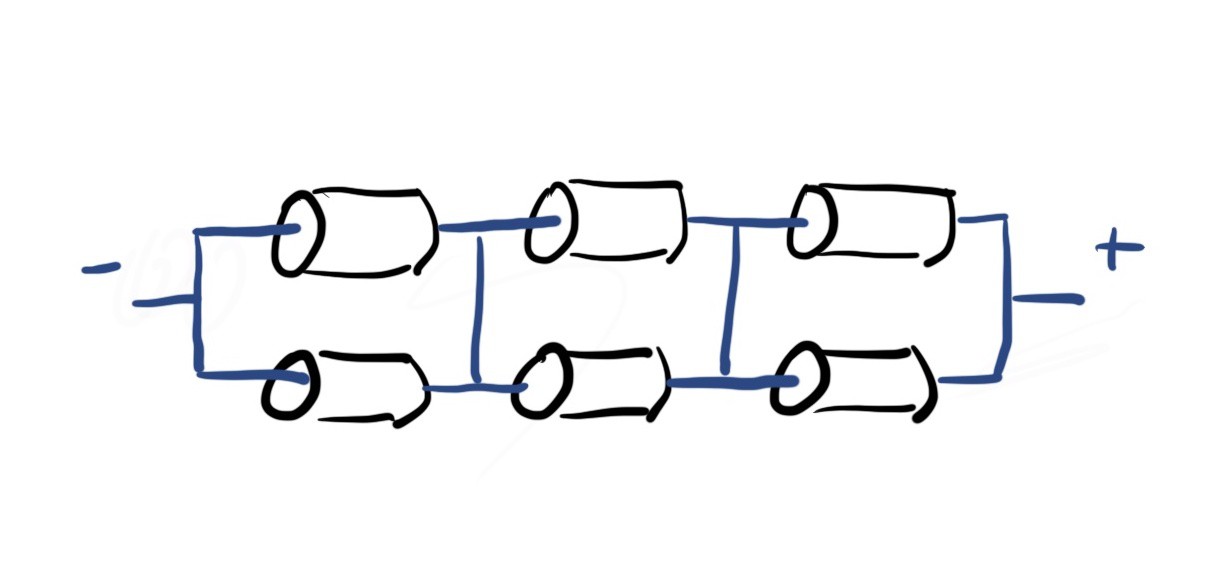
I'm aiming for roughly 12V in the setup. With Li-Ion batteries, you cannot really reach that exactly, so I'm going a bit below, with a 3S2P battery setup, meaning 3 batteries in series, and 2 in parallel, which comes out to a nominal voltage of 11.1V (3.7V * 3). Here's a picture of what that looks like electrically:
![]() ---------- more ----------
---------- more ----------
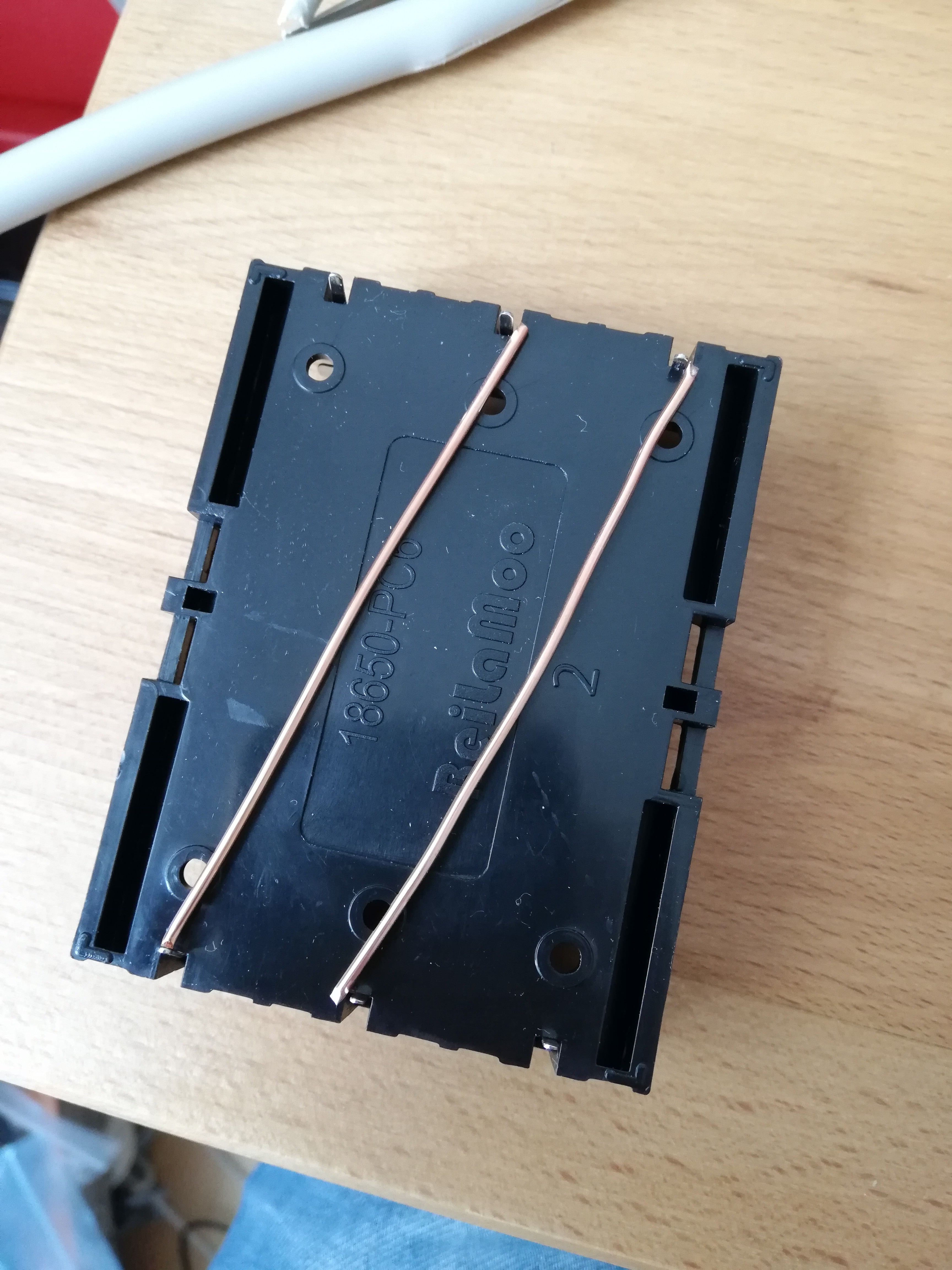
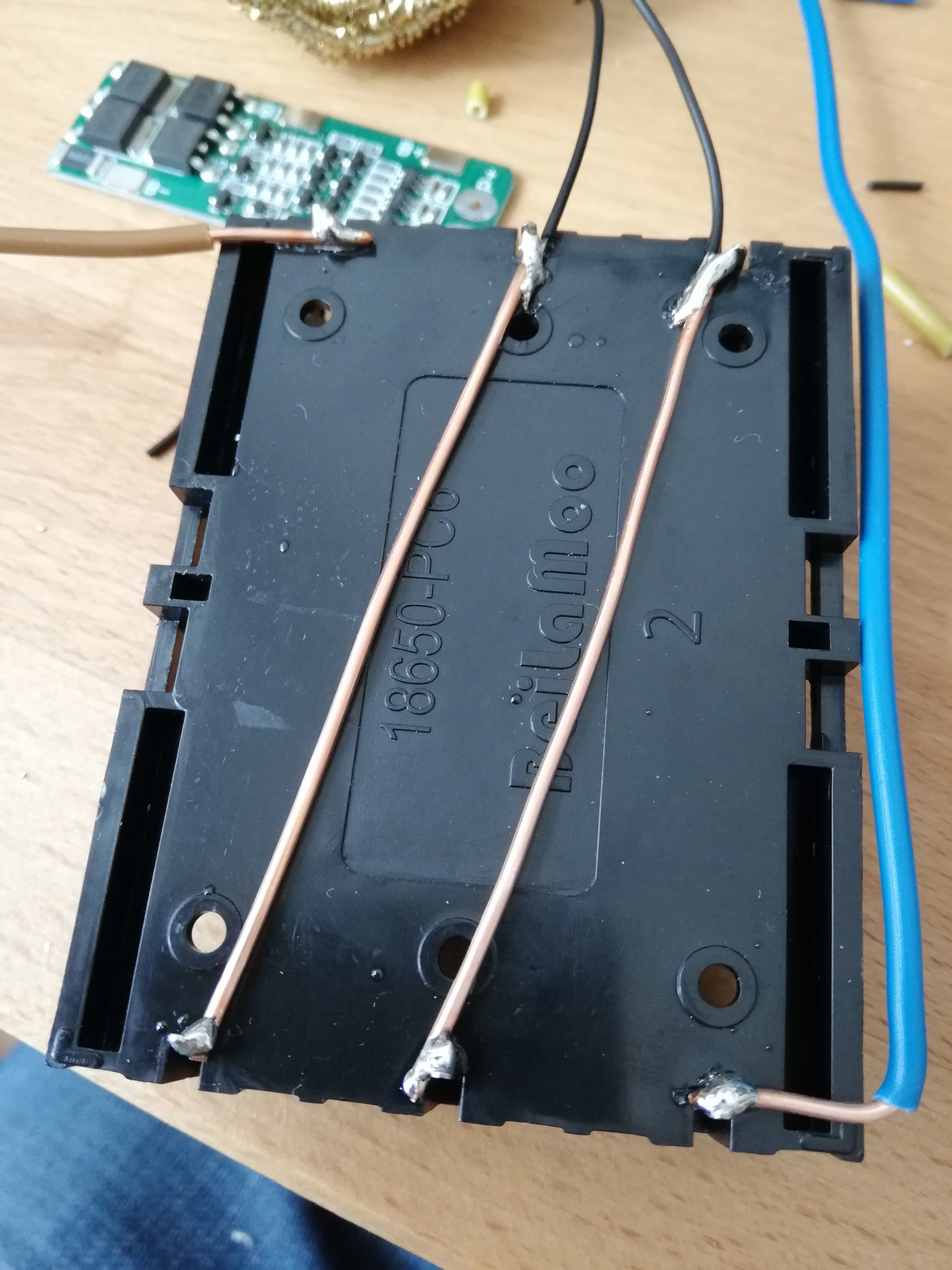
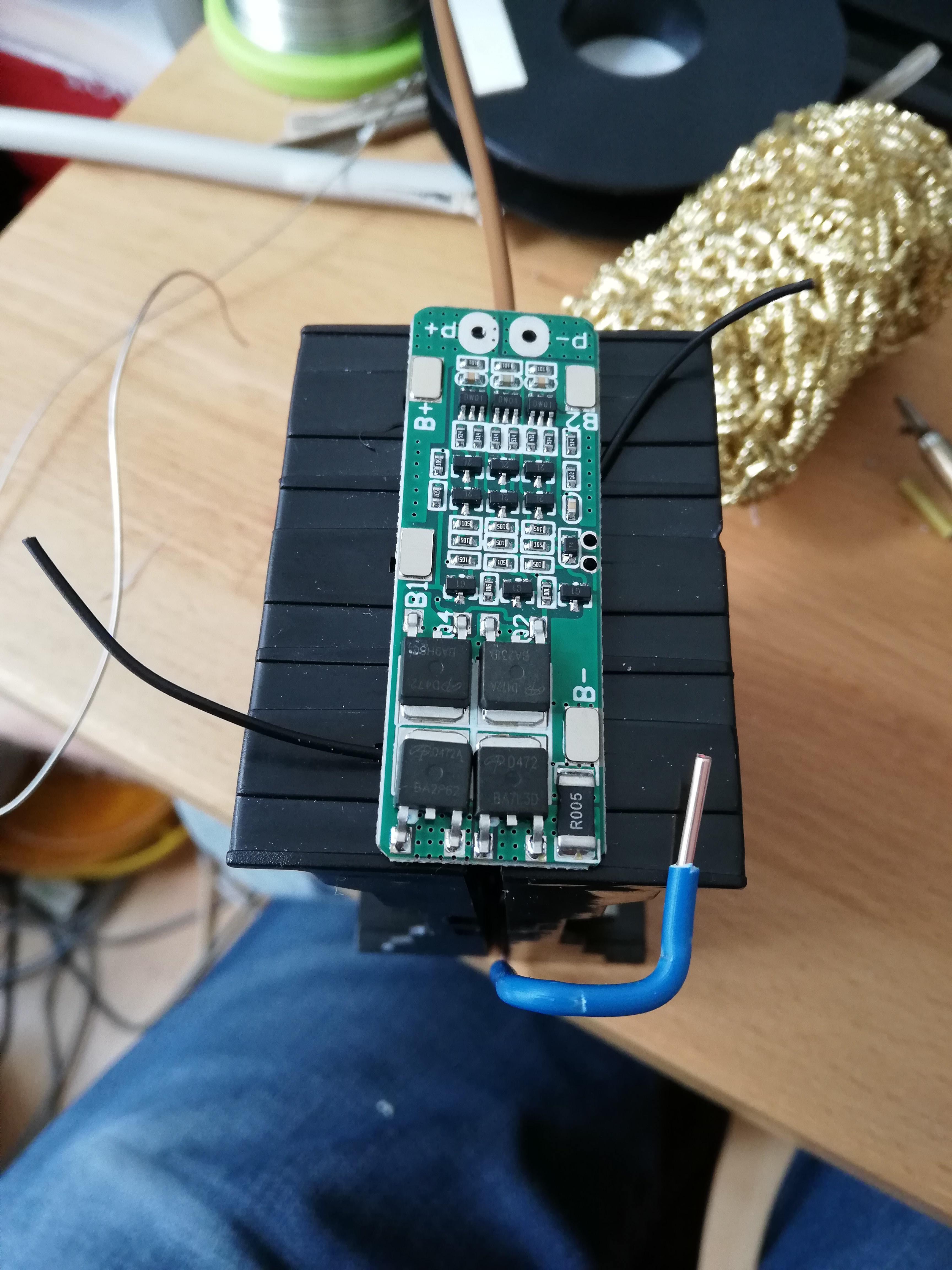
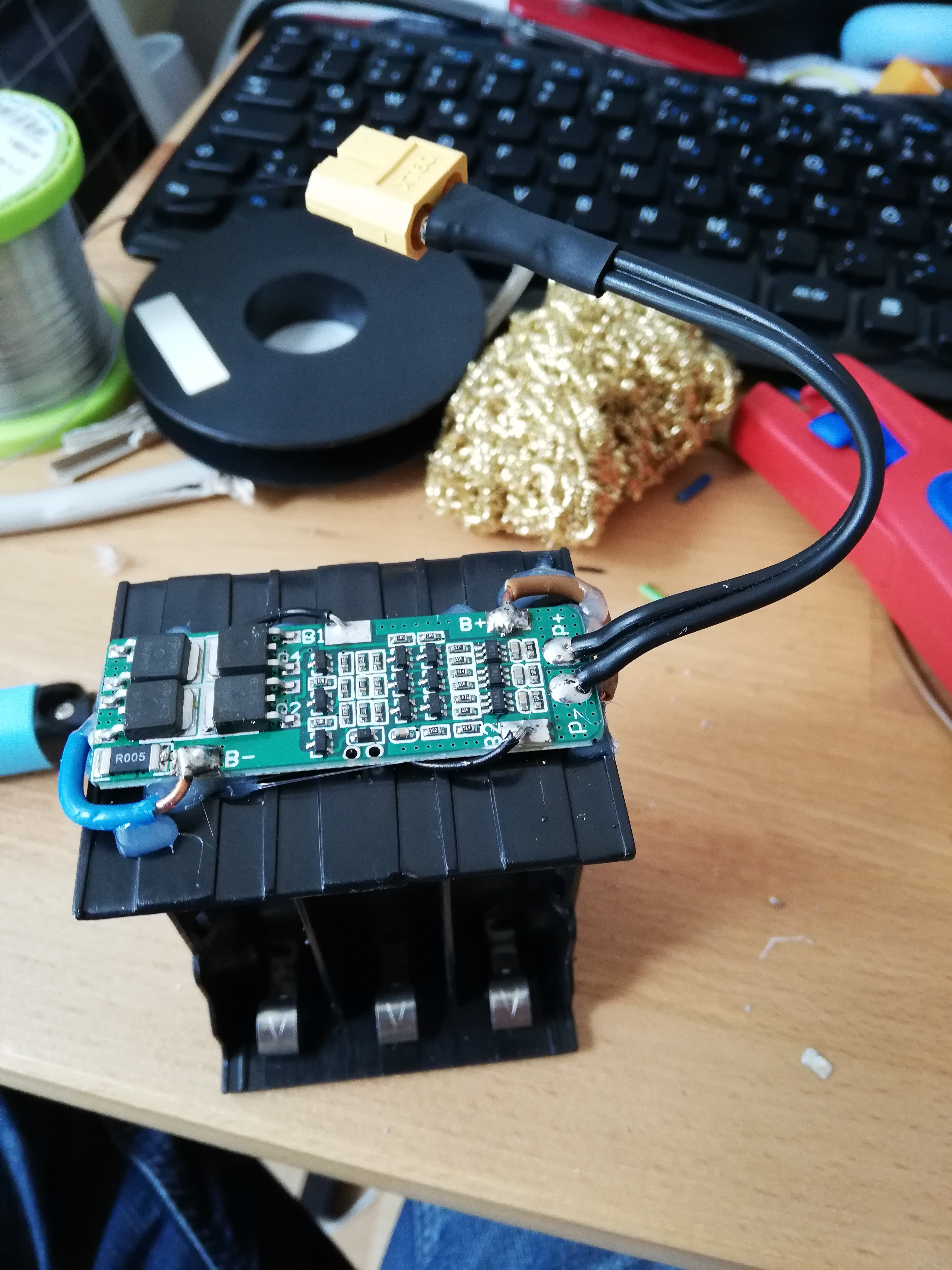
So that'll be two of the battery holders, connected back to back. In addition, there will be a Battery Management System, to make sure nothing goes up in flames. Let's get soldering (and hot gluing apparently)![]()
![]()
![]()
![]()
The BMS board has plates on the battery connectors, I assume to allow for spot welding of the metal strips you normally see on battery packs. When I tried soldering my wires to them, I found that there were also just soldered on, and came off quite easily when applying a good amount of heat. Without them, there's just regular plated holes to solder to, much nicer if you have wires and not a metal strip.
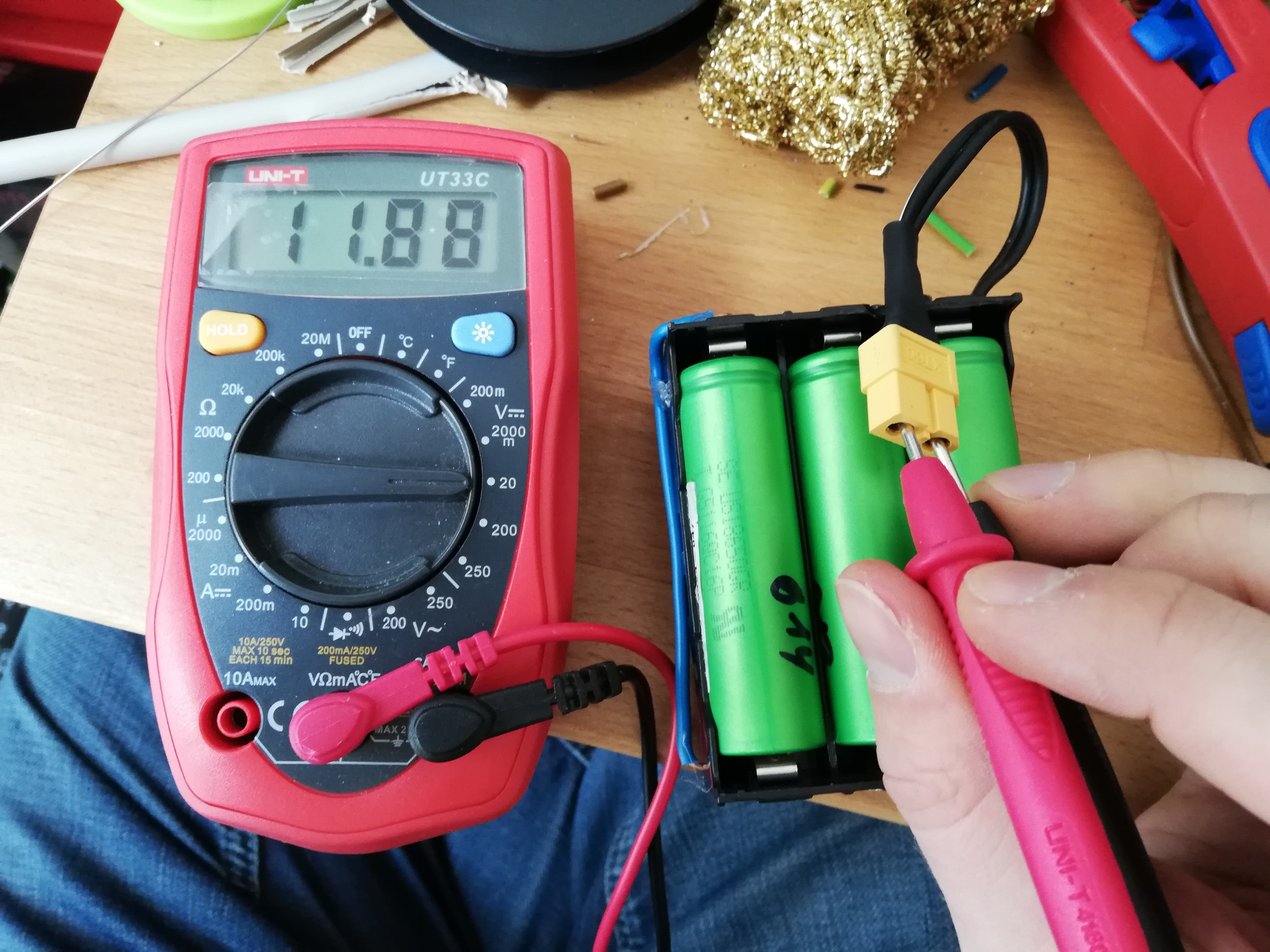
I plugged in 3 batteries for testing, and the pack shows proper voltages on all pins and on the XT60 connector. So I'll call this a success for now.
![]()
-
Solar Charger - The Circuit
04/07/2021 at 22:08 • 0 commentsI'm planning to use a 3S Li-Ion setup, which results in a 11.1V nominal voltage. I wanted to be close to 12V to be able to use stuff made for cars with it without having to deal with DC-DC conversion.
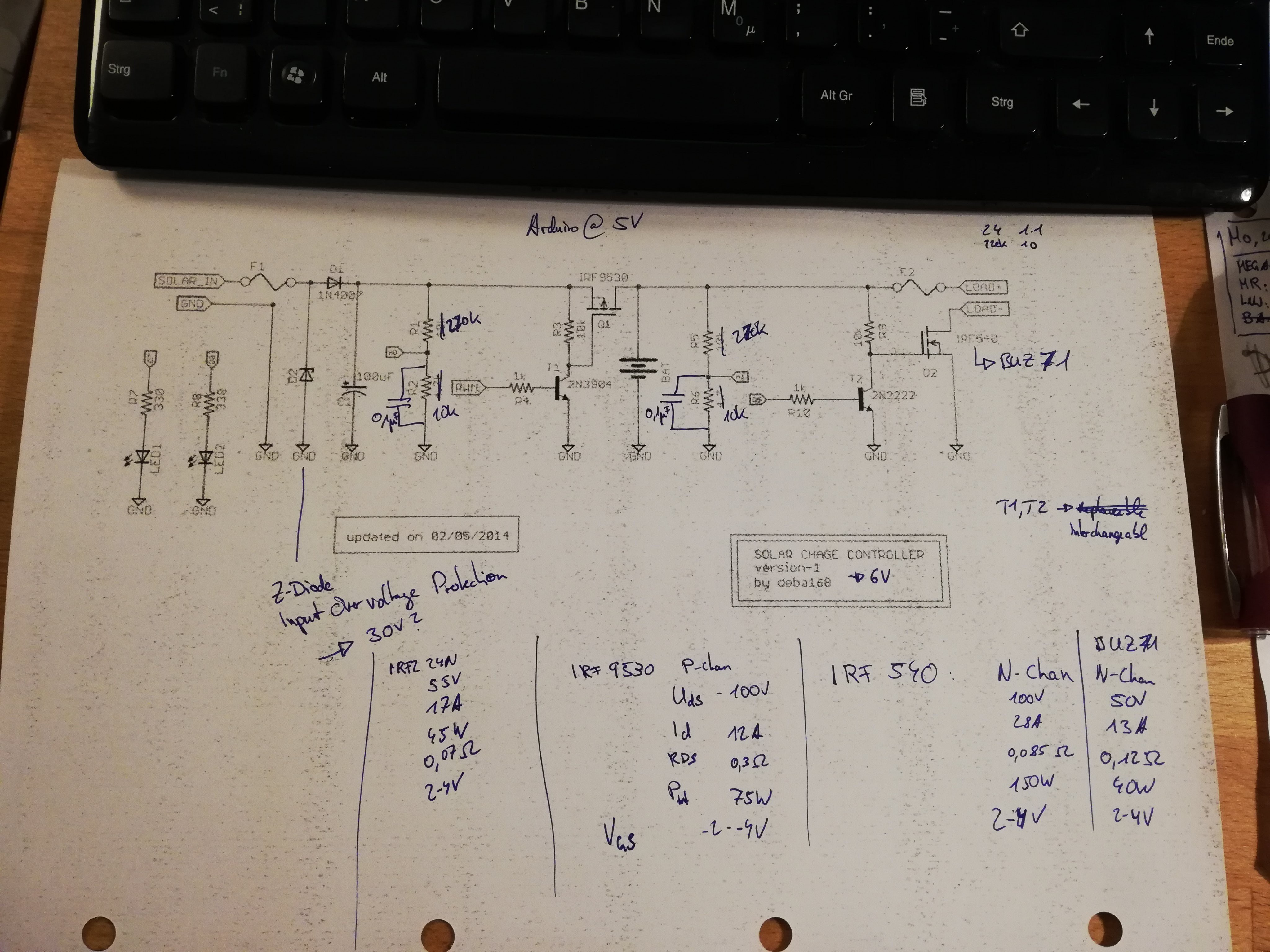
There are many cheap solar chargers out there, which have adjustable cut-off voltages, but unfortunately, none of the ones I tested so far allow to be adjusted enough to deal with 3S Li-Ion packs. So I'll have to build my own.
I decided to use a https://www.instructables.com/ARDUINO-SOLAR-CHARGE-CONTROLLER-PWM/ as a reference for the solar charger, but decided to make some changes to it. It's originally designed for 6V, so some of the protection circuitry needs to be adjusted, and I want to use a smaller OLED screen instead of the regular LCD. On top, I'll have to change the firmware quite a bit. I started drawing up my changes right onto a printout of the circuit.
![]()
Next step will be prototyping this. I thought I had all the parts around, but seems like I don't have any P-MOSFETs around, so I'll have to wait until the next big parts order, or find something in the bottom of my parts piles.
-
Getting started
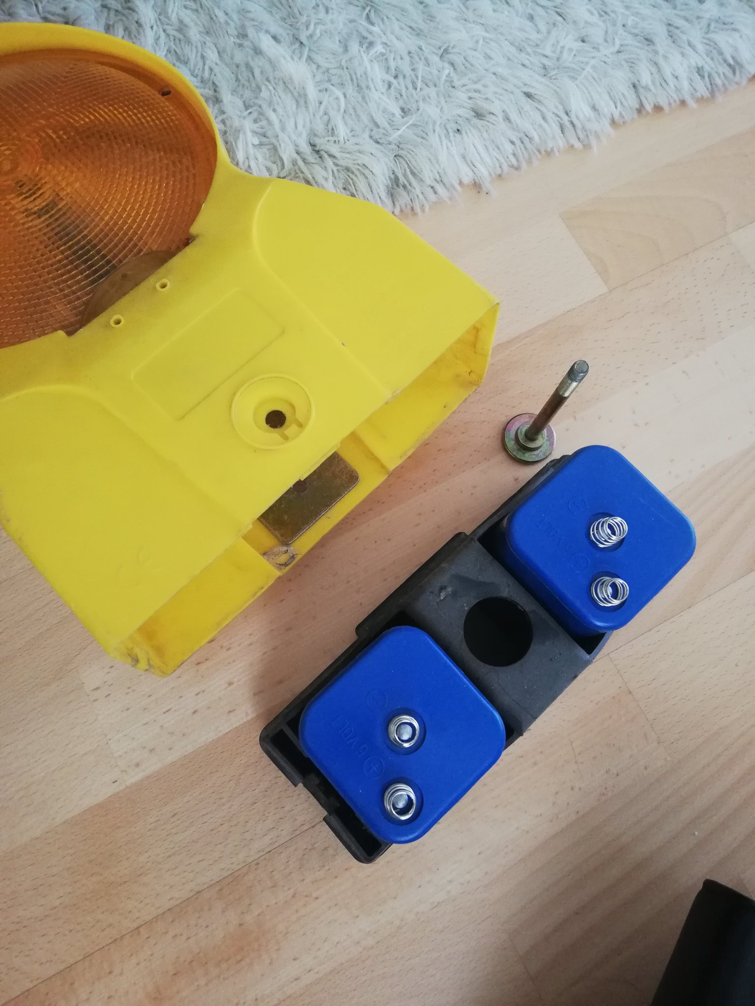
04/05/2021 at 22:09 • 0 commentsThis roadwork warning lamp has been with me for years, and after not having done anything fun with it since then, I decided to try to convert it into a portable power station with some Li-Ion batteries, a solar charge controller, a proper lamp, and whatever else I can fit in there.
These lamps normally run on big chunky 6V batteries, but I'll try to replace them with 18650 Li-Ion batteries, in a 3S configuration (11.1 V nominal).
![]() ---------- more ----------
---------- more ----------
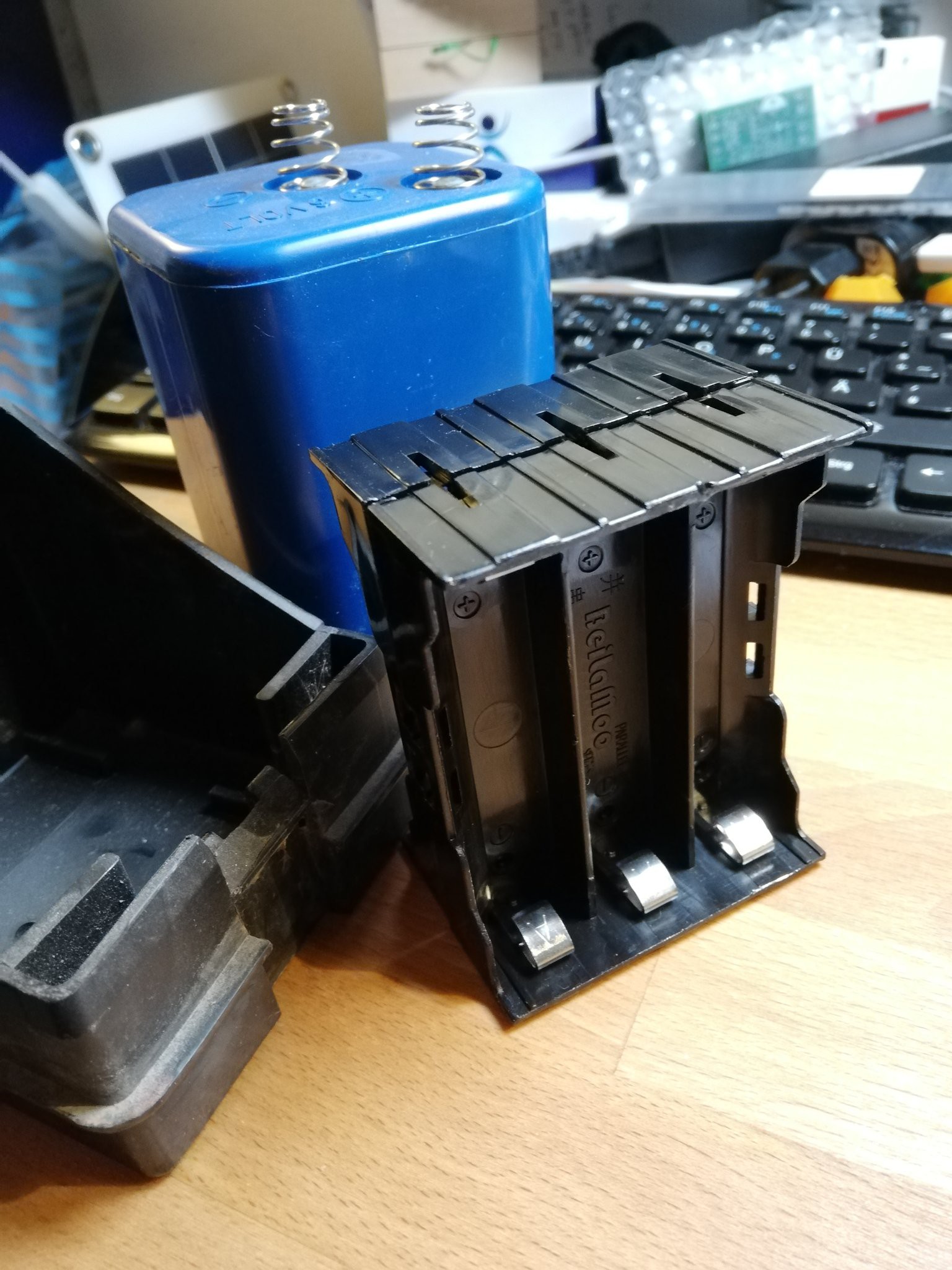
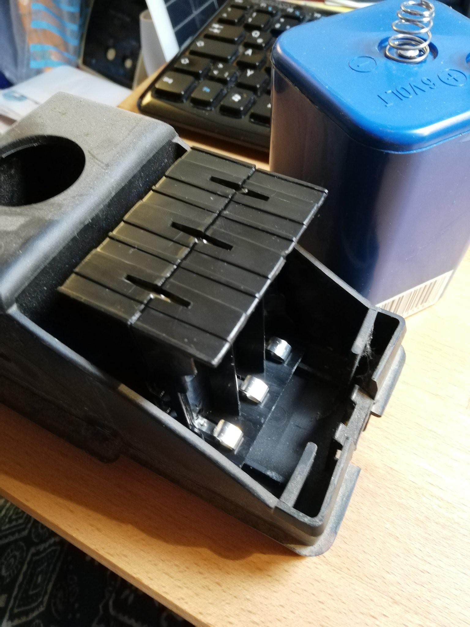
I don't have the means to make my own welded battery pack quite yet, so I'll use these 18650 battery holders for now. Two of them go back to back and fit very well into the spot where the batteries were before, so I'll have a 3S2P battery configuration for now. That would give me somewhere around 400-500Wh of battery capacity, depending on what kind of 18650 I decide to get. Not great, but good enough for a start, and I can always build a bigger battery pack later.![]()
![]()
Roadwork Warning Lamp Solar Power Station
Hacking a roadwork warning lamp into a solar power station
 tiefpunkt