Alexander Williams
-
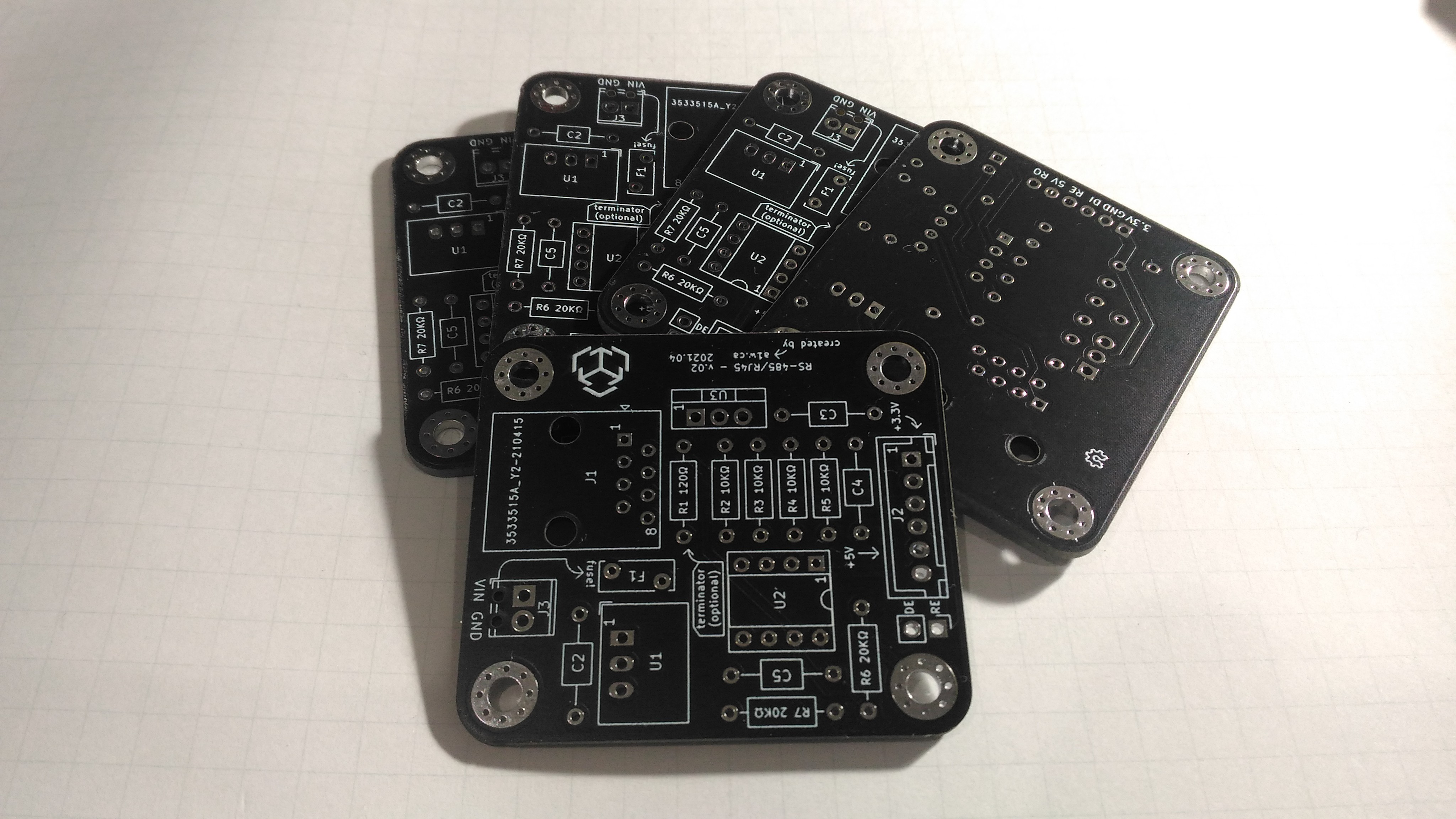
Yay, v.02 boards have arrived
04/29/2021 at 04:24 • 0 commentsThe v.02 boards arrived today and they look sooo much better than v.01. Although this board is a through-hole only version, it should be 100% functional.
![]()
I'm going to solder the components and make 2 modules, run some tests, and then make another post with my results.
Hopefully I can order the v.03 module before the weekend.
-
Updated v.03
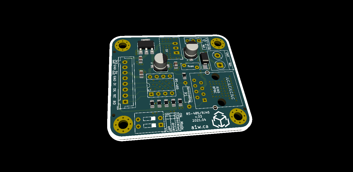
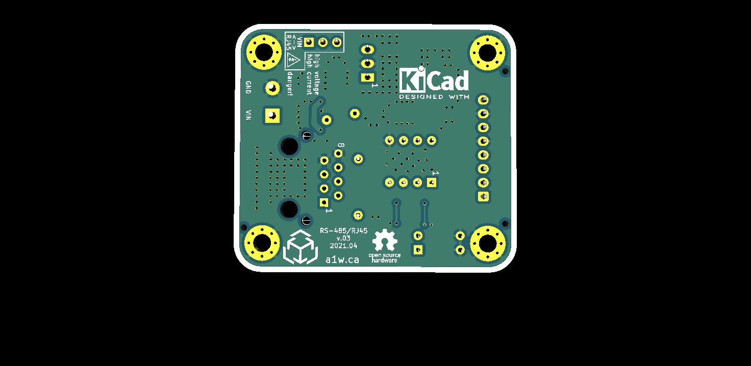
04/29/2021 at 03:23 • 0 commentsI'm still waiting for the v.02 boards to arrived, so in the meantime I continued over-engineering the v.03 board and ended up with this:
![]()
In this iteration, I liberally added thermal vias under every component which could potentially get hot with 2~3A of current going through it. I also added more silkscreen labels to clearly identify things, and switched from 6-pin to 8-pin JST header. This adds an extra GND pin to make it easier to wire 5V to one device, and 3.3V to another device. I also decided to break out the DE pin so it's possible to control that pin through an MCU as well.
![]()
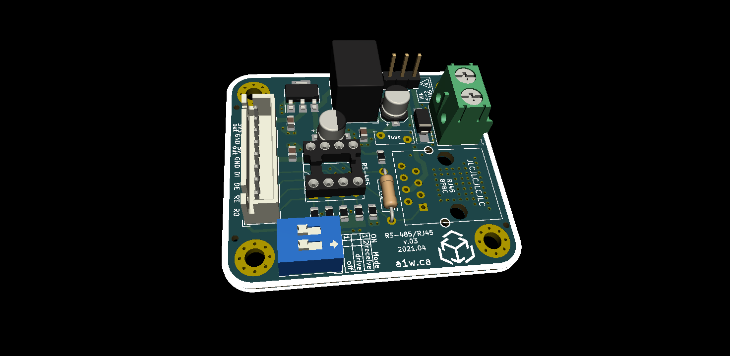
The DIP switch allows for manual configuration of the RS485 operating mode (receiver/driver/off), and there's a 3-pin header which can connect VIN to RJ45. I initially wanted to use a high-current rocker switch, but it adds a lot of bulk and cost to the module, so I opted for a riskier 3-pin header with scary warning labels.![]()
The important thing is to avoid touching those headers while the board is powered. That's common sense, but hey...
Anyways, since this is more of a development/hacker board, people are free to wire things as they wish (ex: skip soldering the 3-pin header, use an 8-pin header instead of the JST connector, etc).
The 3.3V LDO was initially user-selectable, but I decided to opt for an SMD SOT-223 LDO which is limited to 1A but should be fine for powering a small MCU like an Arduino Pro Mini.
For now I'll keep waiting for v.02 before making further changes to v.03.
-
SMD v.03 complete
04/21/2021 at 04:25 • 0 commentsI've completed v.03 of the SMD board. Here's a preview without the through-hole components:
![]()
This board will still require a fair bit of hand soldering, but it's still much less than the fully through-hole board.
So far I'm quite happy with this one after iterating on it a few times, but I still don't plan to order the test batch since I haven't received v.02 yet.
-
Alternatives on Tindie
04/17/2021 at 04:42 • 0 commentsBefore starting this project, I searched through Tindie for projects similar to my idea.
I did find a few options which could technically work, but they all seem to be missing one or two key features.
![]()
This project was interesting because it's designed specifically to drive some LED strips without much fuss. Unfortunately the boards are impossible to mount due to lack of mounting holes, the "kit" doesn't include any components and there's no schematics or other useful information.
LED Data Extender/RS485 and RJ45
![]()
This seemed to be exactly what I wanted, except it doesn't have a voltage regulator so it can only be used to transfer a low current data signal. It's essentially identical to that el cheapo board with an RJ45 for data. I like that it uses a simple dip switch to choose between RX/TX (I might borrow that idea), but the lack of ability to transfer higher voltages (ex: 12V, 24V, ...) was a deal breaker. I think the module is not too pricey, even fully assembled I do think it should probably be priced at $10 or $15 for a pair instead of $15 for one.
RS485 Stick![]()
I'm still a bit confused about what this is. RJ45 to USB? Weird but cool I guess.. The description says it can be used to transfer power and data but it doesn't even have any fuses or voltage regulators. I do like the breakout pins but this is also not designed to be mounted anywhere and reminds me too much of el cheapo at a much higher price point. This module is interesting (because it's weird) but it's sadly not professional enough and lacks important usability/safety features.RS485 HAT (daisy-chain, bus powered) Raspberry Pi
![]()
I saved the best for last. I like this because it literally does everything I want, and it even supports full-duplex communication thanks to the larger transceiver. Unfortunately it has two flaws which I couldn't overlook: 1) it's designed for a RaspberryPi, instead of being a standalone module. 2) it's really expensive. It uses the de-facto standard 40-pin RPi header, but the RPI pins are then completely blocked off, so you can't even stack another shield on top of it! Overall I think it's well designed but that IC and voltage regulator are pricey, and that 40-pin header leaves you with a lot of hand-soldering (2x more solder points that my board).Conclusion
As you can see, there are definitely many solutions to this problem, including some I didn't mention. But for my needs they were all lacking something important. Hopefully I created something that will be useful for others as well.
-
Why not el cheapo RS485?
04/15/2021 at 07:17 • 0 commentsThere's a popular el cheapo RS-485 module available on the internet:
![]()
The cheapo module is good because it's ridiculously inexpensive and "does the job". It's fine for prototyping, however...
The cheapo module is missing some key features:
- RJ45 connector
- Voltage regulators (5V/3.3V)
- Good design
Missing RJ45
You don't need to use RJ45 for your differential pairs, but I like it because it's ubiquitous and cheap. The only danger is connecting an actual ethernet device to that port. It could get ugly, but otherwise I feel like it's a must-have for any RS-485 communication over long distances (ex: 15m).
Missing voltage regulators
The module is powered by 5V and if you want to power a device (ex: WS2812 LEDs) over a long distance, how to you get power to them? Well sure you can pass current through a long thick cable, but you'll see a voltage drop due to the wire resistance. If you need 5V and 1A at the LEDs, how much voltage do you send? 7V? 10V? 12V? well, it depends on the wire gauge, length, material, shielding... your other option is to have a power source near the LEDs, but that's not always possible.
Wouldn't it be easier to just have a voltage regulator near the device?
Missing good design
I didn't want to get to this (I mean really, am I debating the demerits of a $2 module? haha), but the cheapo module has pre-soldered 2.54mm (0.1") pins. This means they must be connected to jumper wires or a breadboard or a homemade perfboard. Even worse, the board is literally too long to fit a typical breadboard, so now you need TWO breadboards for each module.
10mbps over 1km on a single pair of wires
A simple 46mmx22.5mm module to route power and differential signals (RS-485) over RJ-45

/i/1304/products/1406-2013-10-13-18-43-39-photo1.jpg?1606306133)
/i/882112/products/2020-11-07T00%3A37%3A48.482Z-2020-09-29T12_04_06.364Z-724292671%20%281%29.jpg?1606306133)
/i/6523/products/2014-02-19T22%3A54%3A41.121Z-Photo%20Feb%2007%2C%208%2046%2034%20PM.jpg?1606306133)
/i/03741/products/2020-10-21T20%3A24%3A23.992Z-IMG_0328.JPG?1606306133)