Second Life UPS
Table of Contents
- 1. Design overview
- 2. Component layout
- 3. The battery
- 4. The output board
- 5. The controller board
- 6. AC power connection
- 7. Final device
1 Design overview
I have decided to build a UPS that would power my home network equipment rack using lithium-ion 18650 cells.
First let's lay out some basic design considerations
- should fit the equipment rack in a 1U format
- it should provide 12V DC, 5V DC as well as 230V for the switch
The current list of devices that need to be powered by the UPS together with their nameplate voltage and current consumption information:
| Device | Voltage [V] | Current (max) [A] | Power (max) [W] | Notes |
|---|---|---|---|---|
| Router | 19 | 2 | 38 | A small form factor PC |
| 16-port switch | 230V AC | 0.1 | 22.5 | Rated at 22.5 W in the technical specs |
| AP | 24 | 0.25 | 6.5 | Rated at 6.5 W (see datasheet), passive 24V PoE Mode B (230V/0.02A) |
| Raspberry Pi | 5 | 2.1 | 10 | |
| GPON modem | 12 | 0.5 | 6 | |
| Total | 83. |
As can be seen there is a large amount of different voltages required in order to power all of the devices, therefore some modifications and compromises will have to be made:
- The UPS will provide stabilized 12 V and 5 V power rails
- The 19V for the router will be provided by a dedicated step-up dc-dc converter based on the very popular XL6009 chip from aliexpress
- The 230V AC will be temporarily provided by a small car 12V -> 230V inverter
- The PoE injector is scheduled to be replaced by an PoE injector which can be powered from DC
- The router will be replaced in the future with a Mikrotik Routerboard or a PFsense appliance from https://teklager.se/en/pfsense-hardware/ that both can be powered from DC
- The switch will be modded to have a DC power supply
2 Component layout
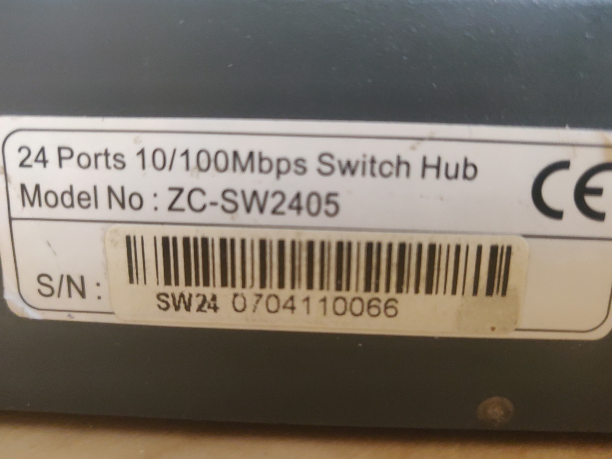
The 1U case that I used for this project is a case from a ipTime ZC-SW2405 switch:
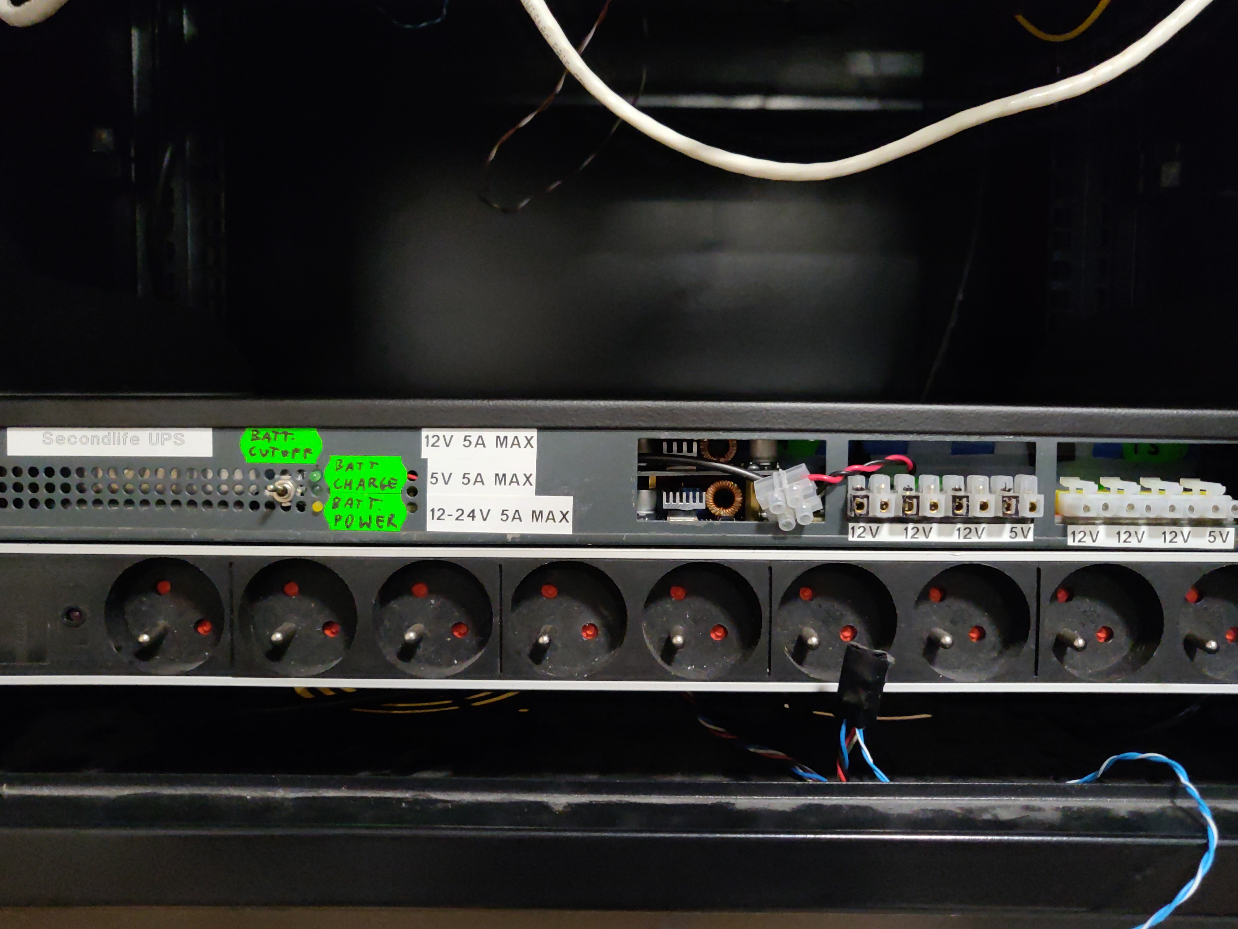
I have removed everything from the switch case including the power supply as it was only providing 3.3V and did not have enough power. The case has 1U dimensions, to be exact 16 cm x 44 cm x 4.4 cm. I have also drilled out all of the studs holding the original PCBs to the case in order to fit the battery and AC PSU. This has proven to be a hindrance however as I had to remake some of them later to mount my custom boards.
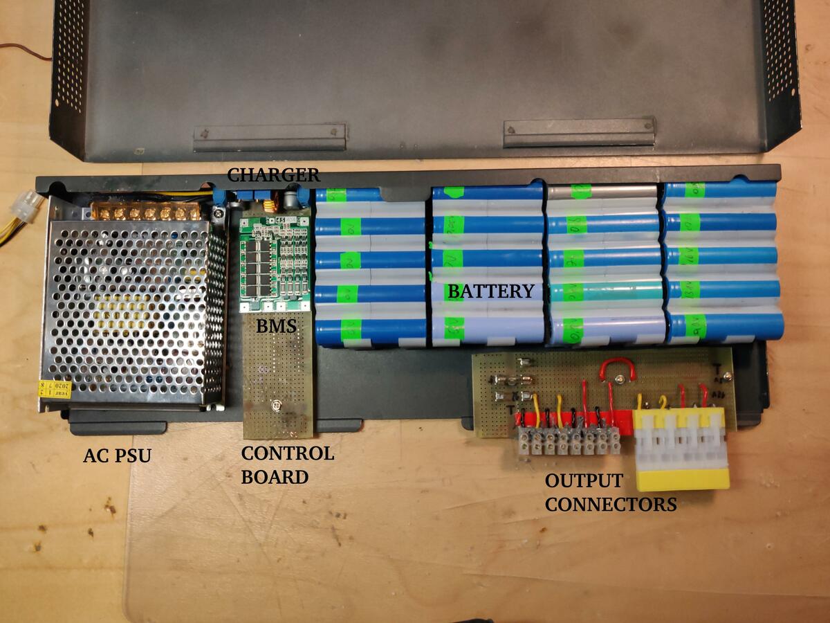
The case size puts a limit on the size and shape of two biggest internal components - the battery pack and the 230V AC power supply. I have devised the following placement for these components.
From the basic layout the following elements are COTS components:
| Brand | Model | Parameters | Notes | Link |
|---|---|---|---|---|
| KAYPW | Switching Power Supply | 24V 5A 120W max | https://www.aliexpress.com/item/33042313383.html | |
| 40A 16.8V Balance REV 2.3 | 4S 40A | https://www.aliexpress.com/item/4000026248298.html | ||
| XL4015-B CC/CV module | 5A CC/CV, 75W max | Li-Ion charger | https://www.aliexpress.com/item/4000383898441.html | |
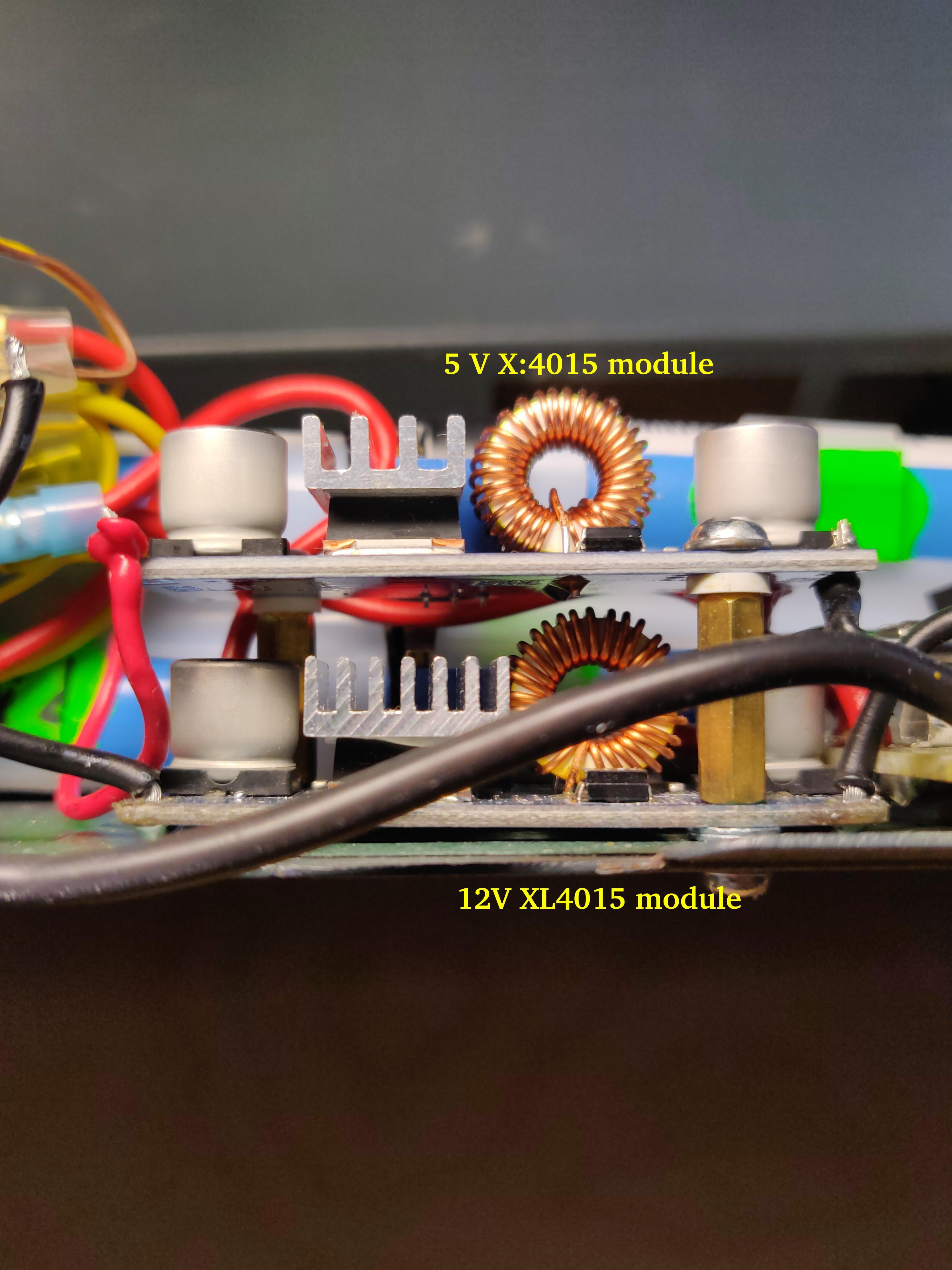
| XL4015 buck dc-dc converter | 5A max | Provides 5 V and 12 V outputs | https://www.aliexpress.com/item/4000796650052.html |
3 The battery
The battery for the UPS was built using 18650 Li-Ion cells recovered from hoverboard battery packs. These are cheap no-name cells with not a lot of capacity left in them (around 800 mAh) each but I figured that a UPS would be the perfect idea to utilise them. They will operate under low current load per cell so their internal resistance shouldn't be a problem. The UPS will be mostly sitting idle and charged so the cells won't get further capacity fade from cycling. The cells have been screened for self-discharge and excessive heat generation during operation. As the space in the case is pretty tight heat might be a problem therefore two thermal fuses tripping at 75 °C have been fitted in the battery as a safety feature. The battery will be protected with a 20A car fuse and paired with a 4S 40A BMS.
As a further step to increase the lifetime of the cells the top charging voltage will be limited to 4V per cell. This...
Read more » Enki
Enki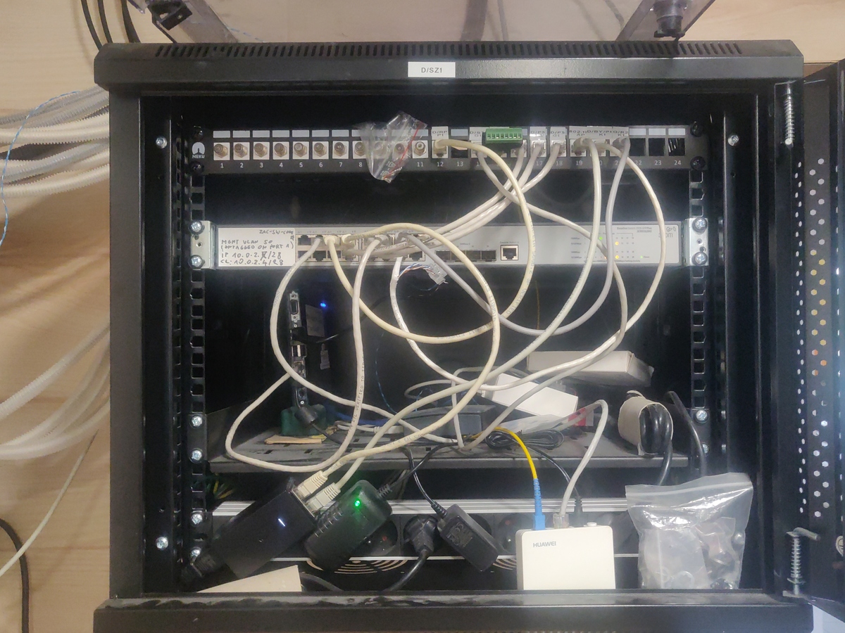


 Dominic Buchstaller
 AIB
AIB
 IoT-devices, LLC
Yes, the cells I used were old ones, they had around 50% nominal capacity. What do you mean by charging separately? If you connect the cells in series they charge and discharge at the same time. If you don't connect the cells in series you will get very low voltage which is not practical to use.