Time has come to poke at the display and see what color comes out. The simplest test that we can do, is to apply a constant voltage for an x amount of frames.
The controller can apply 9 different voltages (-30V -25V -15V -5V 0V +5V +15V +25V +30V). We already know that 0V doesn't do anything, so we can focus on the other values. I made two sets of waveforms one positive and one negative.
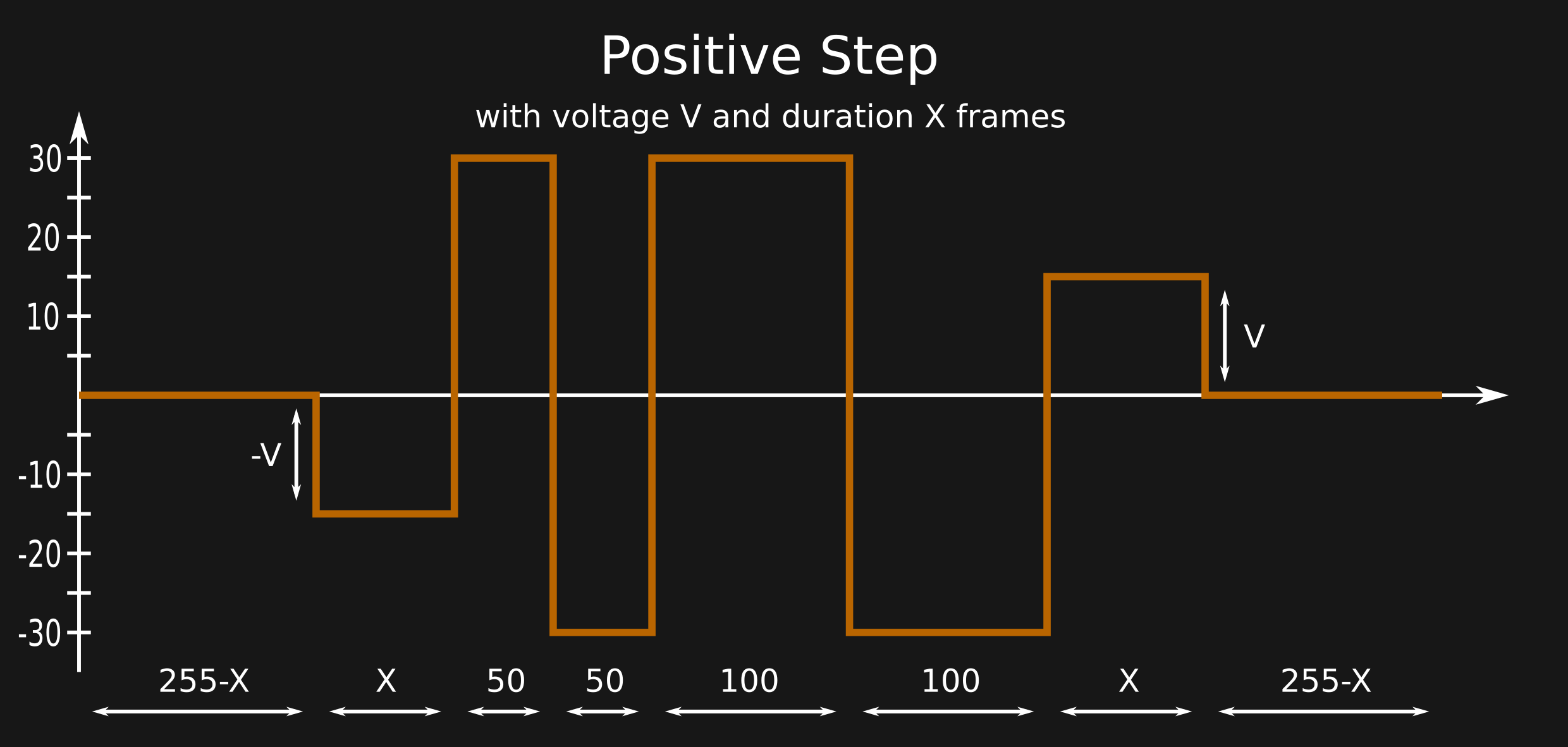
Starting with the positive one. The picture below shows the waveform. It is made up of 3 phases. The first one is to prevent any DC buildup in the panel. The second serves to drive the particles ard towards the top and bottom layers, leaving the display in the extreme optical state. The last phase applies the target voltage for the desired number of frames.
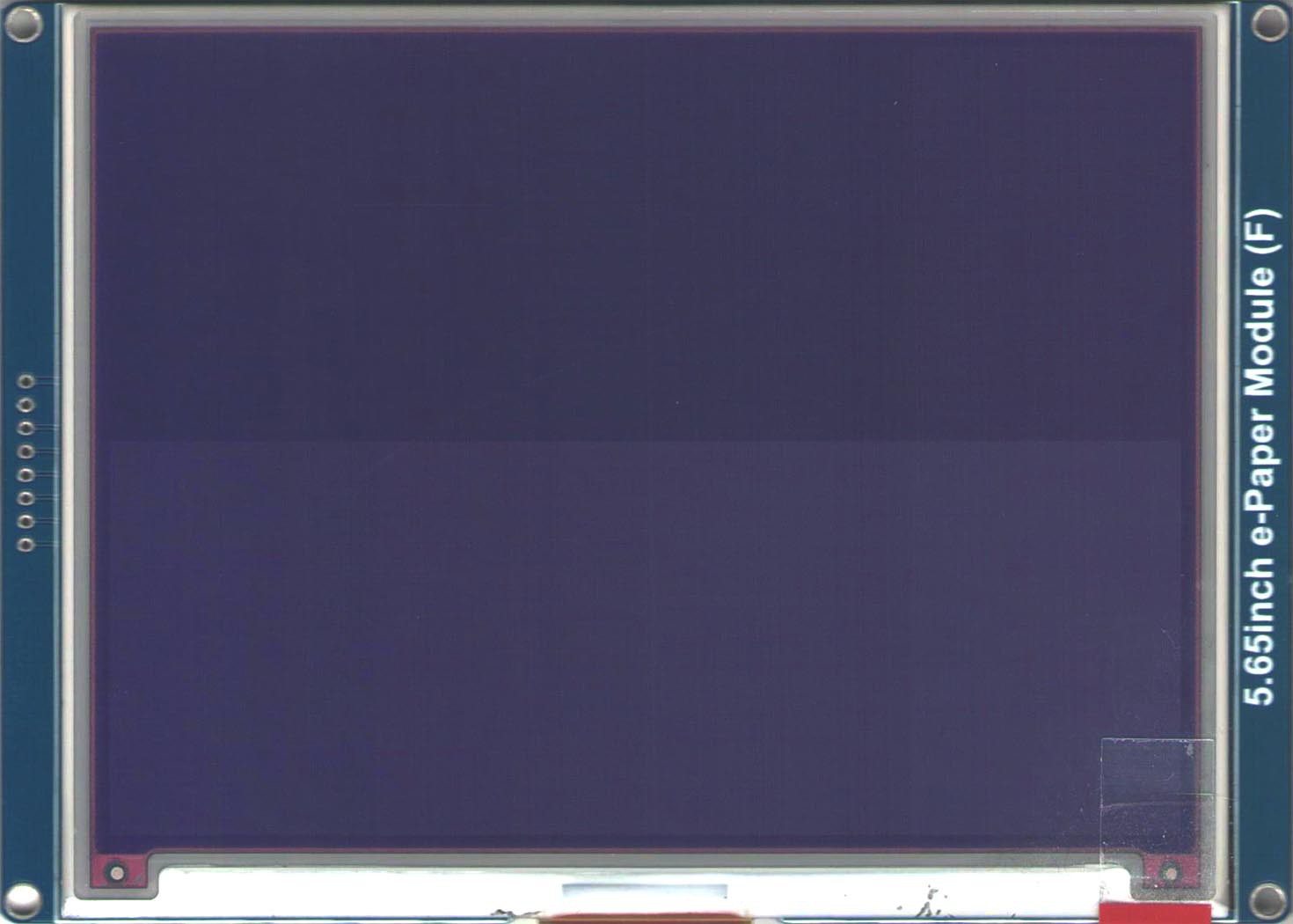
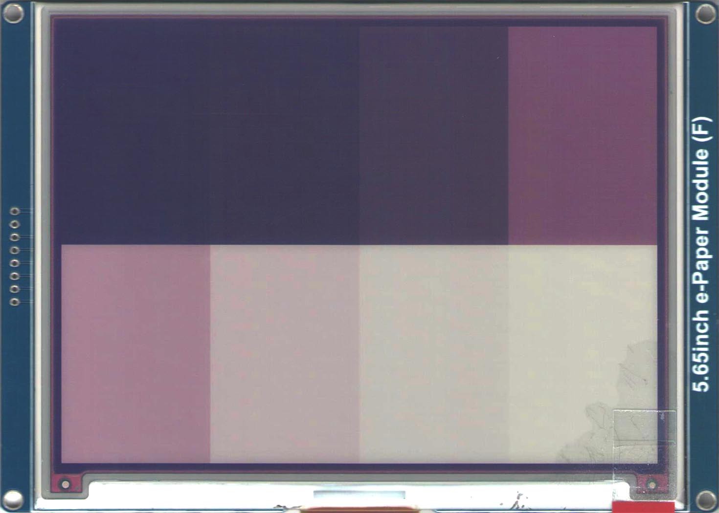
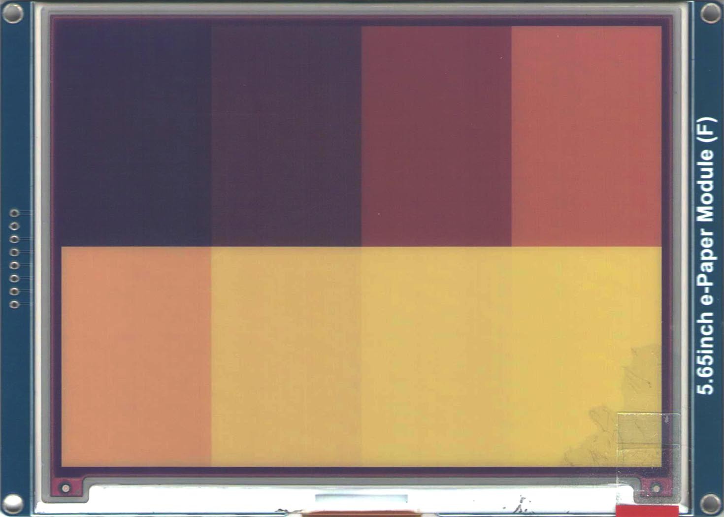
Below are the results of the experiments. For each experiment, starting from the top left and ending at the bottom right, the voltage is applied for 2, 4, 8, 16, 32, 64, 128, 255 frames.
Testing is done at 21°C, framerate is 50Hz.
 |  |
 |  |
The negative waveform is the same as above, with all the polarities reversed. It is made up of the same 3 phases. The first one is to prevent any DC buildup in the panel. The second serves to drive the particles ard towards the top and bottom layers, leaving the display in the extreme optical state. The last phase applies the target voltage for the desired number of frames.
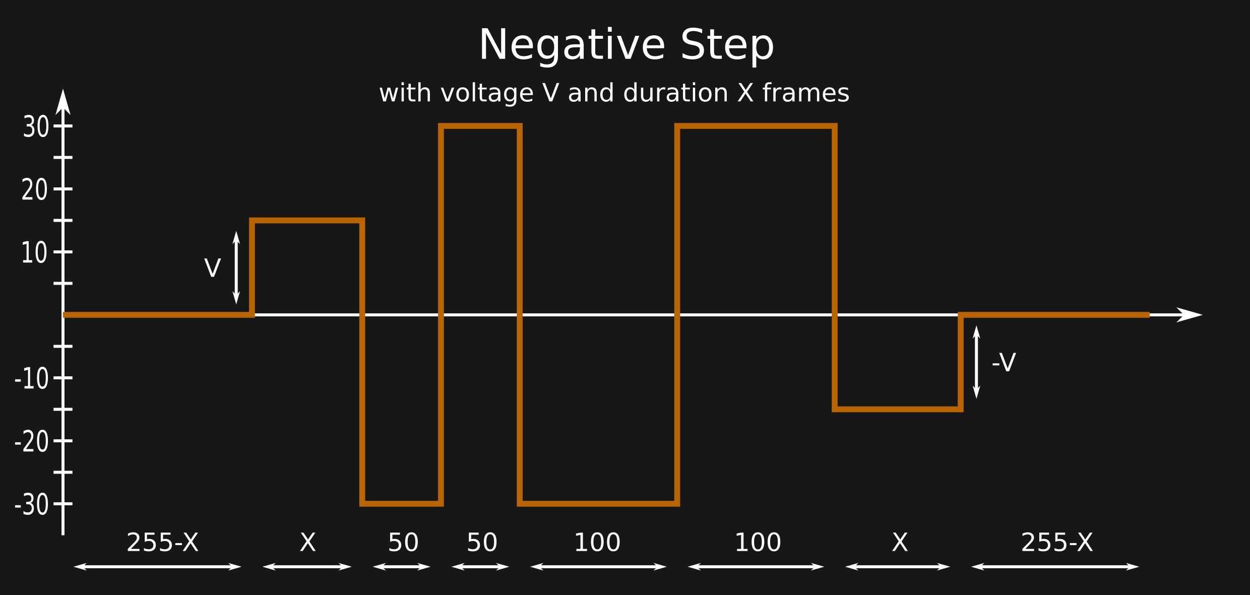
Below are the results of the experiments. For each experiment, starting from the top left and ending at the bottom right, the voltage is applied for 2, 4, 8, 16, 32, 64, 128, 255 frames.
Testing is done at 21°C, framerate is 50Hz.
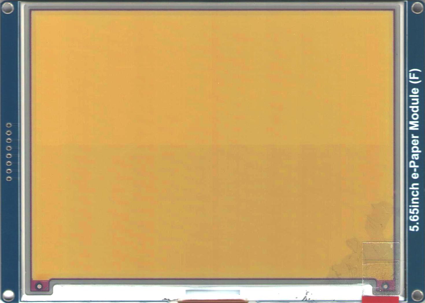 | 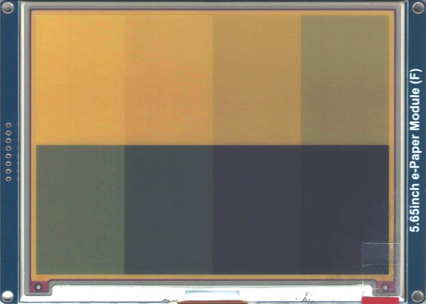 |
 | 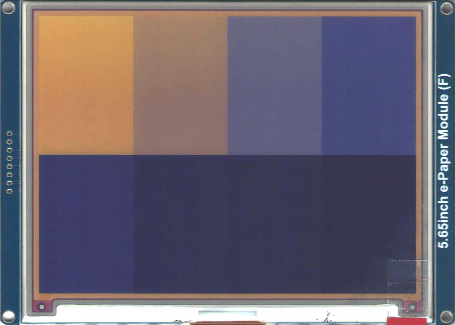 |
Conclusions
What can we derive from the positive step?
- There isn't much change at 5V.
- We can clearly see that white and yellow particles are negatively charged.
- The yellow ones are faster than the white ones, but only if the applied voltage is at least 25V.
- White particles are quite slow, at 25V they take 255 frames to reach the top.
- Cyan seems to be faster than magenta, at 15V the initial dark blu color becomes pink before fading to white.
What can we derive from the positive step?
- At 15V yellow fades to green, which indicates that cyan rises faster than magenta.
- At 25V and 30V yellow goes away quickly, leaving cyan.
What do you see? leave a comment below.
 Manuel Tosone
Discussions
Become a Hackaday.io Member
Create an account to leave a comment. Already have an account? Log In.
This is indeed some splendid in-depth research ! Especially the FPC-mounted flash dump ! 🤩👍👍👍
I had no idea color pigments were actually translucent 😵. This explains why my custom WKR luts were displaying darker reds than I hoped for ( I was whacking the white pigments down when trying to depolarize the cups on white-black-red EPDs, assuming I was manipulating B&R pigments in a white non-polar medium. 😅 )
I'd love to see more waveform experiment, especially around the green region. It seems the green tints are finicky to obtain ?
Anyway, I've finally frankenstein'ed a Lilygo EPD_T_Display (as the board's silkscreen says), also known as Lilygo EPD-Watch ( [url]https://github.com/Xinyuan-LilyGO/E-Paper-watch[/url] ), swapping the 32MB flash for a 128BM one, and deadbug-mounting an ESP-PSRAM64H on top of it (to manipulate an actual framebuffer). The 5.65" ACep display is directly connected to it. Finally the perfect board to torture EPDs with !
Time to experiment on my side too.
Thousands thanks for this article ! *bows in awe*
Are you sure? yes | no
Nice research. Would like to see code examples!
Are you sure? yes | no
Marvellous work!
Are you sure? yes | no