0%
0%
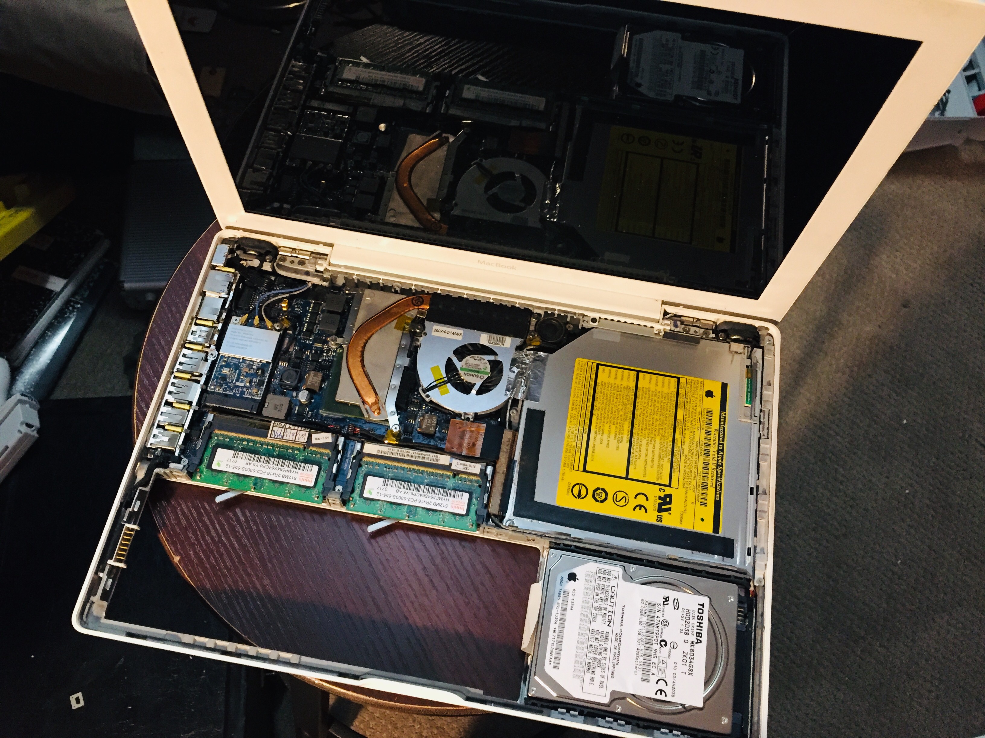
Just another Raspberry Pi laptop. Unless...
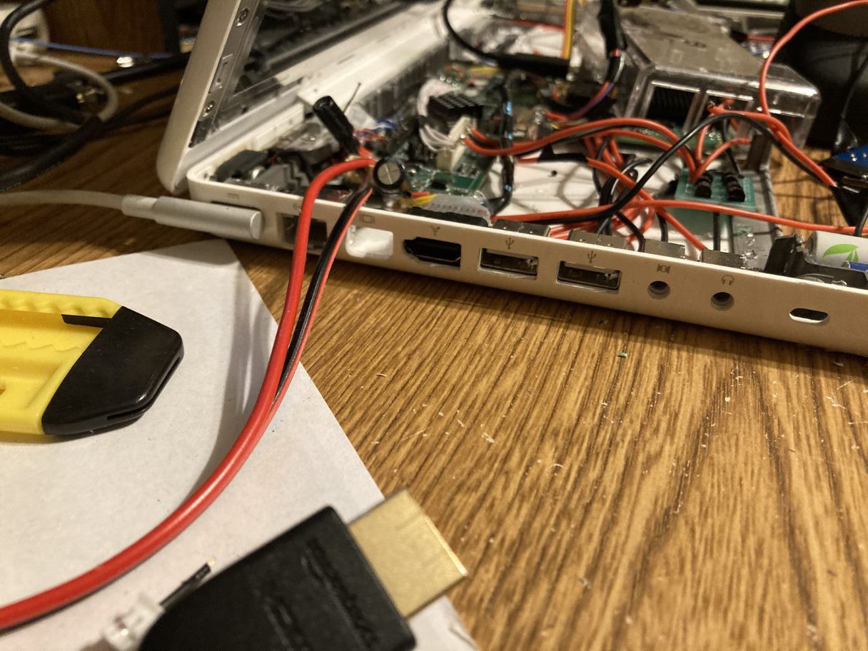
Do you ever get the feeling that there aren't enough Raspberry Pi laptop projects? Well, my original MacBook and I can help with that.
 ty
tyBecome a Hackaday.io member
Already have an account? Log in.
Just one more thing
To make the experience fit your profile, pick a username and tell us what interests you.
Pick an awesome username
hackaday.io/
Your profile's URL: hackaday.io/username. Max 25 alphanumeric characters.
Pick a few interests
Projects that share your interests
People that share your interests


 Bill Peterson
 Dylan Bleier
 nick.r.brewer
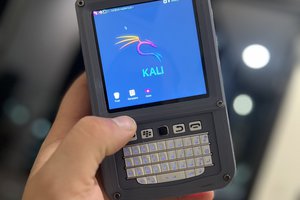
 Taylor Hay
>>> get a USB audio interface that will include a microphone and a decent DAC (the Pi's is notoriously bad).
AppleUSB-C to 3.5 mm Headphone Jack Adapter, unironically. It's great quality audio output, can solder wires to a 4-pin jack and split it into separate mic and headphone connections, supports headset buttons if that's your thing, too. Also, with a "dtoverlay=dwc2,dr_mode=host", you can connect this adapter straight to the Pi's Type-C port and have it work - just need to power the Pi through the GPIO header, then!
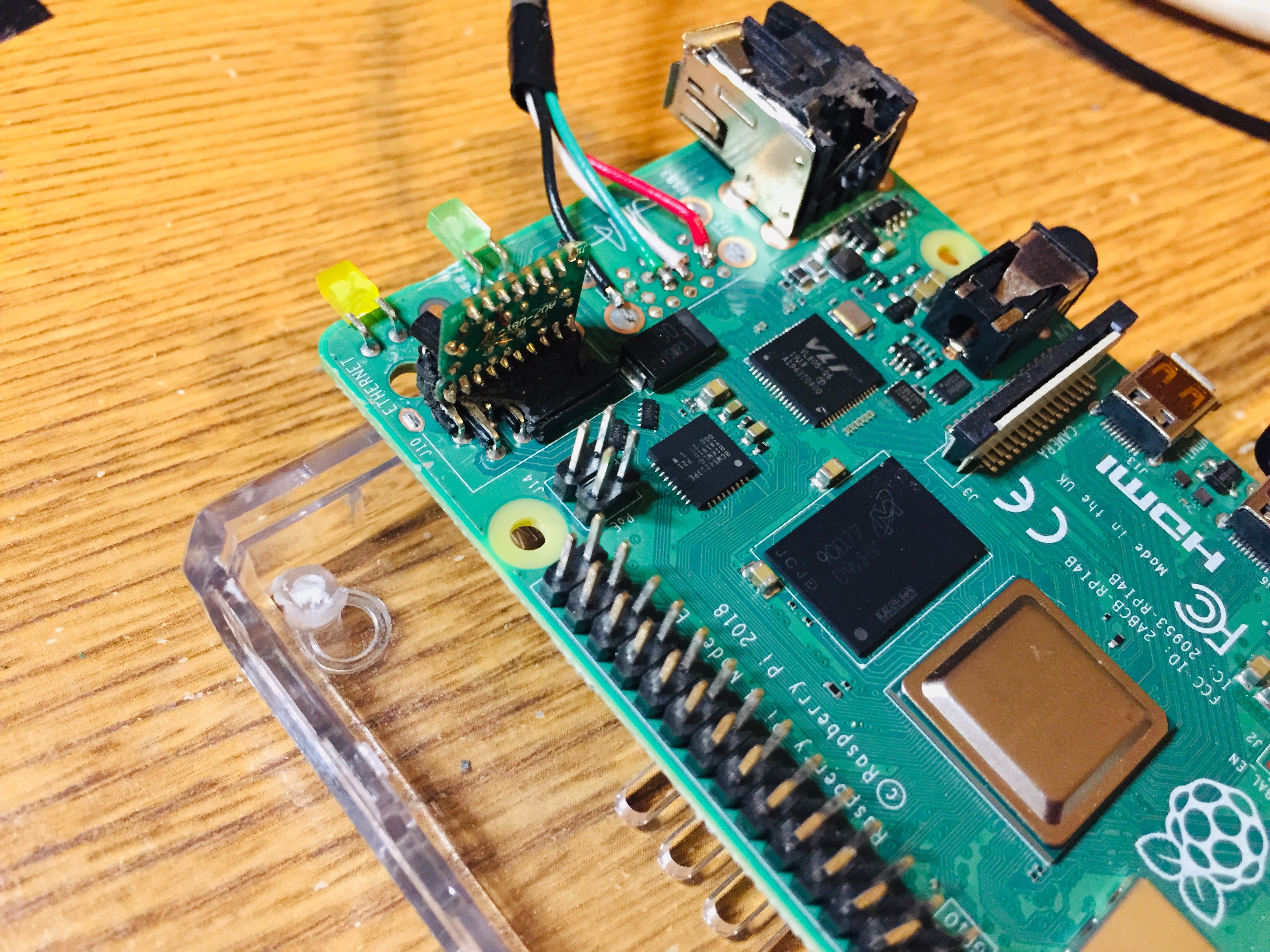
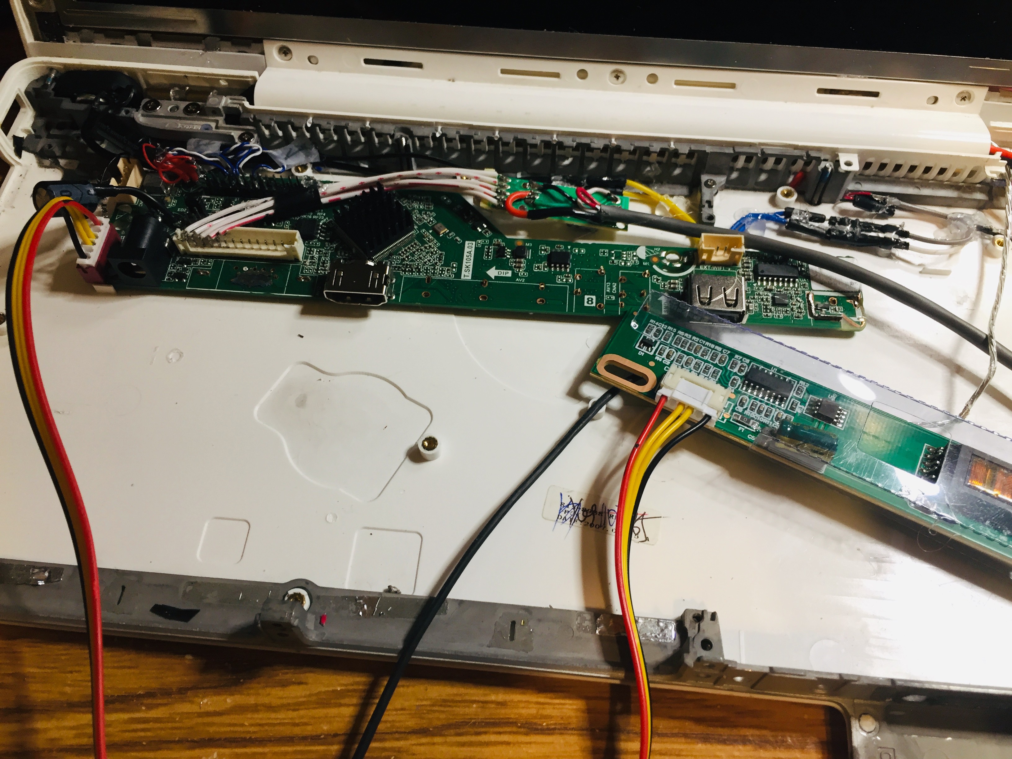
Nice job removing all these connectors!