vincentmakes
-
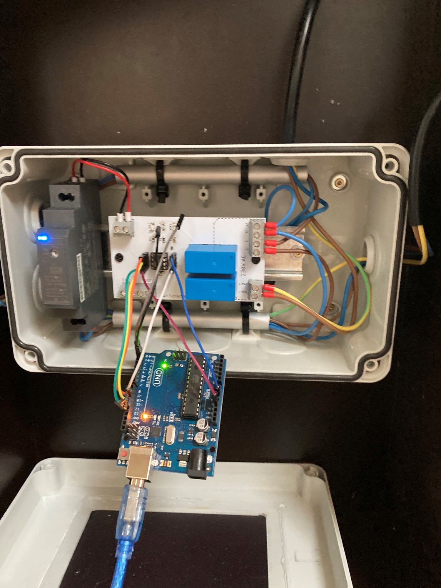
The Arduino Nano Version
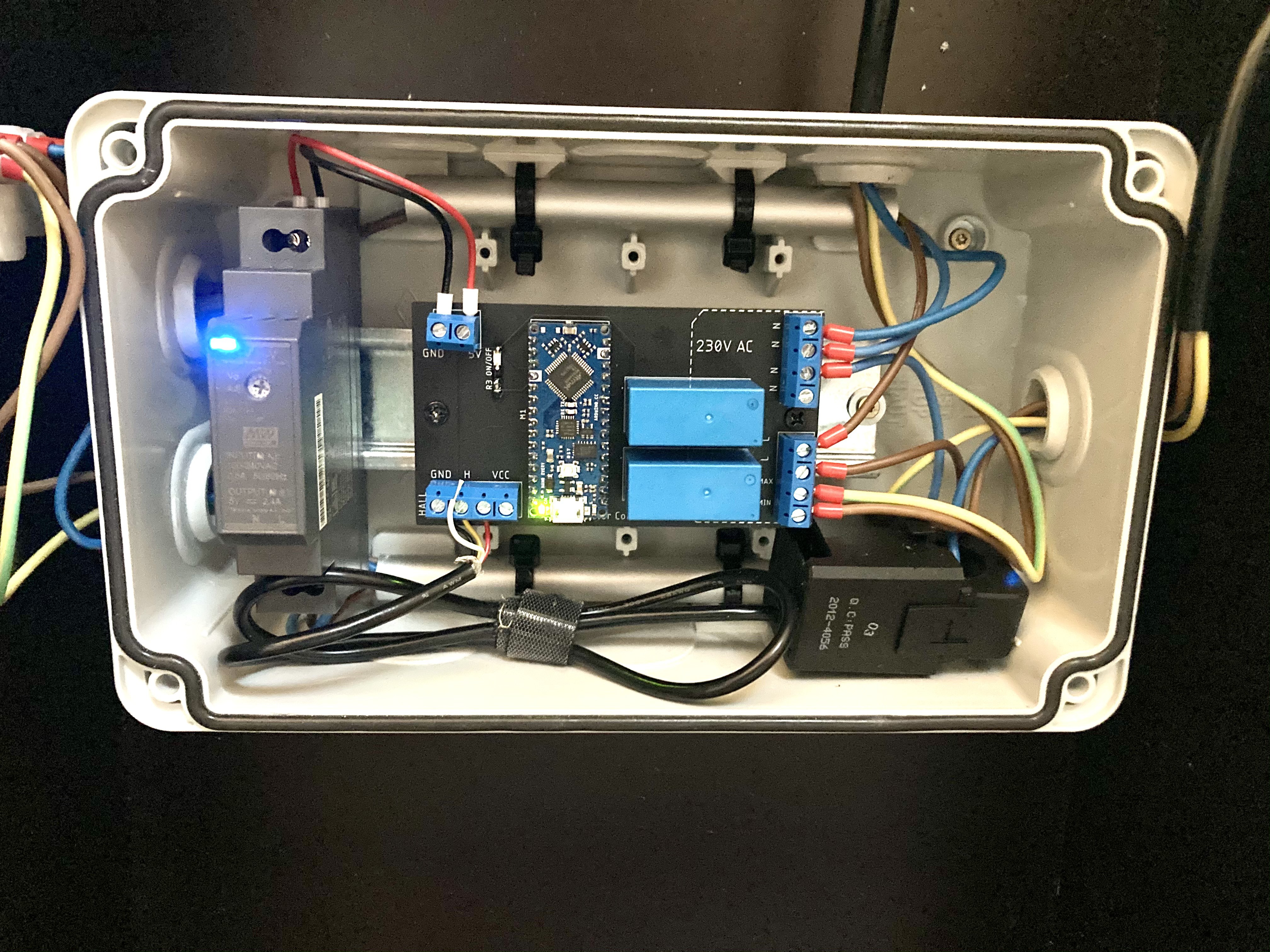
05/12/2021 at 18:39 • 0 commentsSince the programming and simultaneous serial monitoring with the ATTiny85 was a massive pain, I made a Arduino Nano Every version of the PCB and the program.
![]()
Now I can adjust the limits and offset easily while monitoring the values in real time.
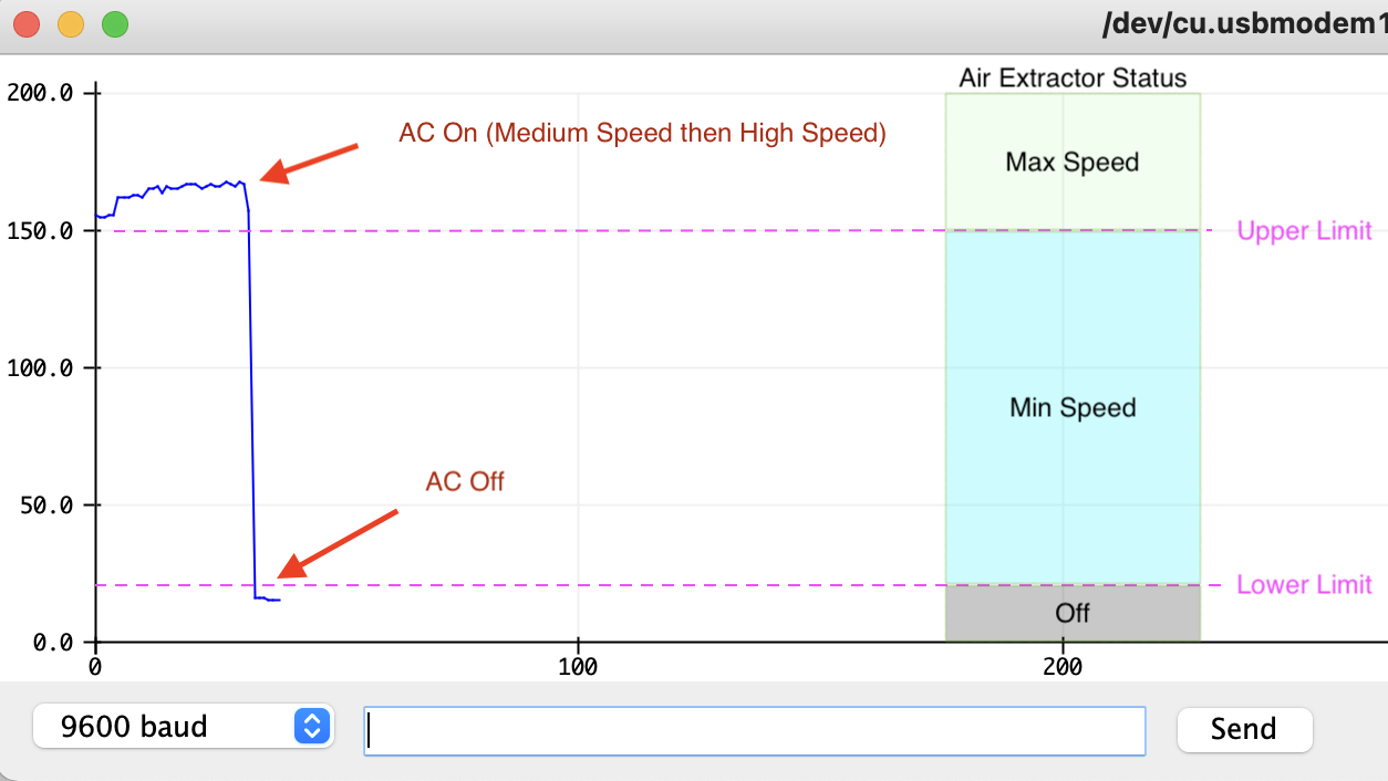
Here's with the plotting of the Vpp value as well as the matching working area of the extractor
![]()
The only issue I noticed is for the lower limit : when I unplug the USB cable, the reading from the Hall sensor varies a bit so if the limit is too low the air extractor keeps running on low speed when the AC is off. I increased a little bit the lower limit blindly in order to correct that and that was fine.
-
Hall effect sensor
05/04/2021 at 16:34 • 0 commentsI received the sensor and wired it. It turned out more difficult than anticipated to convert the signal into a meaningful current.
When plotting the signal, one can notice that when the current consumption increases, the peak AC voltage from the sensor doesn't increase. Instead, the peak to peak value increases.
Overall, it turned out to be easier to measure the peak to peak value (Vpp) without any conversion. It works perfectly in this case because we're not interested into the RMS value per se but rather the relative value: Is the AC switched on, and is it consuming lots of current or not ?
The updated code (production.ino) takes care of that. I need to run more live tests but so far everything is working as it should be.
Here's a demo of the unit working:
![]()
![]()
-
SIT
04/29/2021 at 07:43 • 0 commentsThe board is functioning properly after uploading the sketch: the relays are properly triggered depending on the conditions. However I had issue with the LEDs consuming too much current vs what the Attiny can deliver to both the coils and the LEDs. I should have added some transistors in between to offload that to the power supply.
Not a big deal though, after removing the min/max LEDs it still works perfectly. I will just use the sound of the fan and relays clicking as an indicator instead.
Now onto fine tuning the programming part:
![]()
edit: the steps below have been now replaced by a simple Vpp measurement. It's more than enough for what we want to achieve here. The sketch named Measurement2.ino has been used to display the ADC Vpp values we need.
---
What needs to be adjusted is the sampling phase: In order to calculate the RMS value we need to measure the sine wave current at regular intervals. Each measurement is squared and added to the previous sum. The 3 lines below do that:
currentSampleRead = analogRead(currentAnalogInputPin)
currentSampleSum = currentSampleSum + sq(currentSampleRead) ;
currentSampleCount = currentSampleCount + 1;
Using the timestamps of the serial output I found that this set of instructions takes about 180uS to be executed. I need a measurement every 1ms, so I will add a 820uS delay in the loop.
When a certain amount of measurement as been reached, we can calculate the mean and root of it, giving us the TRMS value.
The testing phase is a bit repetitive with the Attiny85 though. I'm using an Arduino as ISP in the middle and the process goes as following:
- Upload ArduinoISP sketch to the Arduino Uno
- Change the board to Attiny and programmer to Arduino as ISP
- Change wiring from Arduino to Attiny
- Upload Sketch
- Change board to Arduino Uno and programmer back to ArduinoISP
- Upload empty Sketch to Arduino
- Change wiring to serial TX/RX
- Launch Serial Monitor
- Debug, adjust Attiny .ino file
- Repeat
-
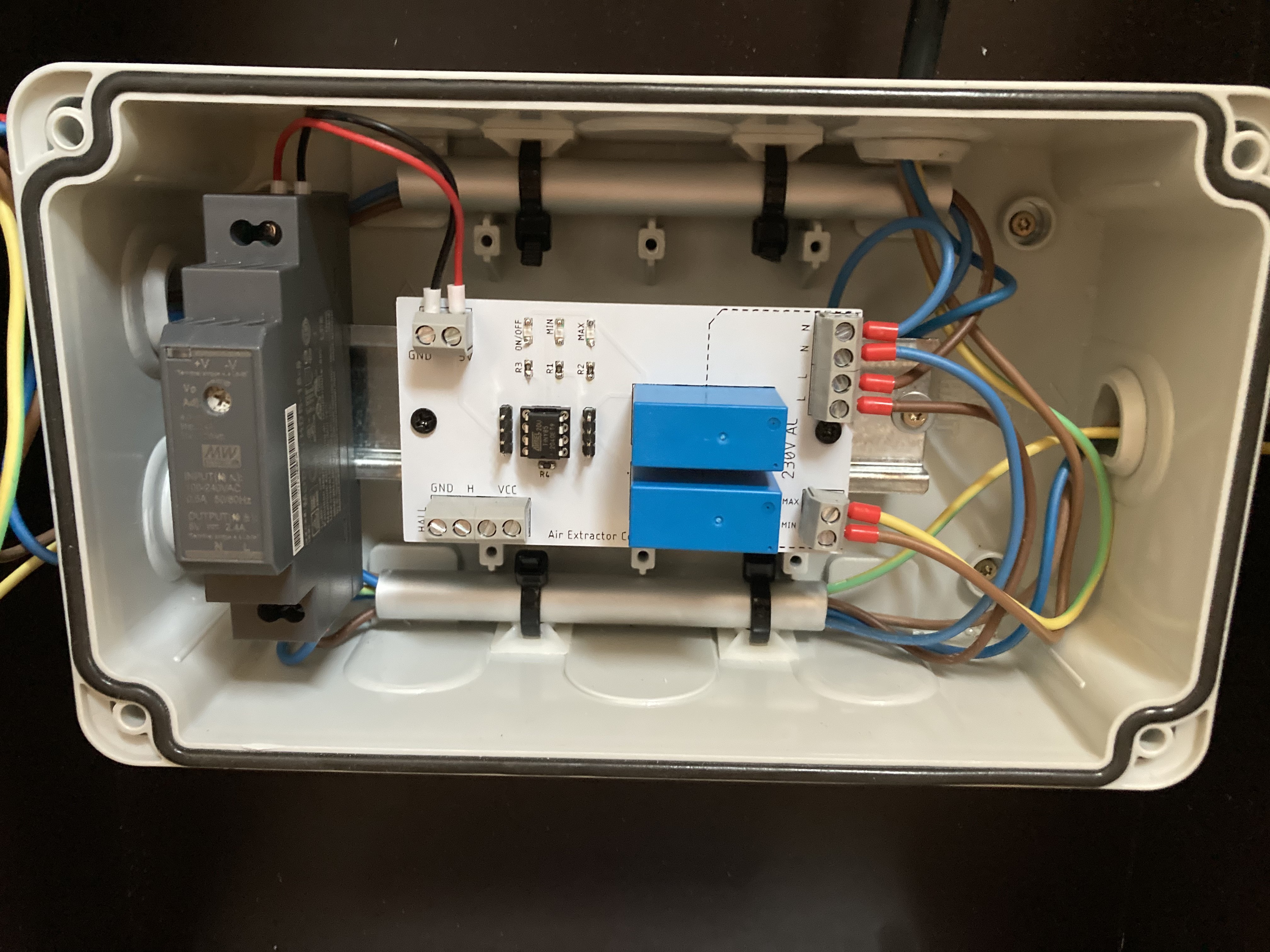
Soldering and mounting the PCB
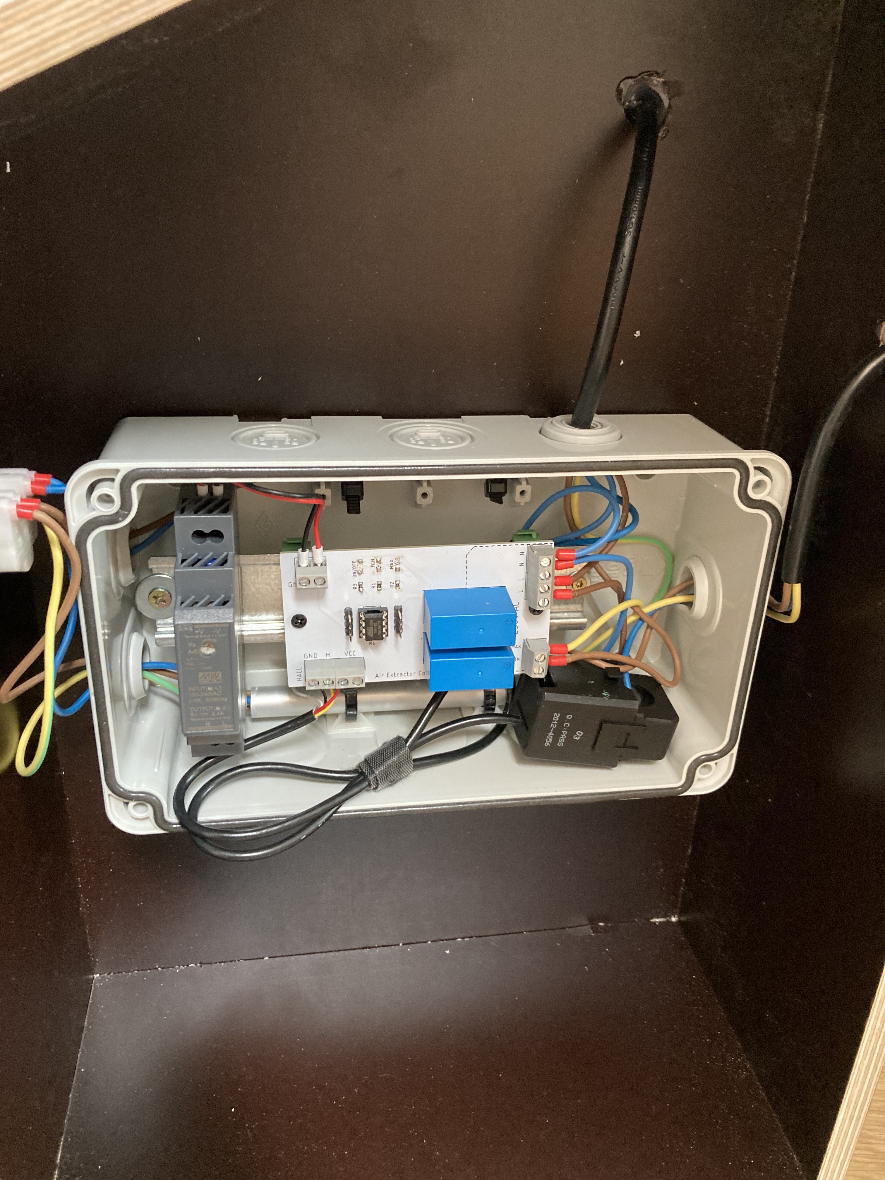
04/27/2021 at 17:41 • 0 commentsI received the PCB, soldered the components and installed everything into the enclosure.
This is when I realised I was missing a connector for a 3rd N cable on the PCB but that was solved easily outside (and stuffed behind). I will correct that on the schematics and PCB printout.
I mounted the PCB on one of those DIN mount from Delock and installed it on the rail along the 5V DIN power supply. I also just got a crimping tool and got carried away:
![]()
I still didn't get the hall effect sensor so I can't test everything together.
However, my next step is to do a dry run where I simulate the AC. In order to do that, I have modified a little bit the production sketch to run the following sequence:
Air extractor Off -> 5s -> Min Speed 5s -> Max Speed 5s -> Off 5s -> etc.
The purpose of this SIT is two folds:
1. Test if what I've done actually works without worrying about the sensor itself which has its own challenges
2.Test if the Attiny85 has enough computing power. I will feed it a fake value to calculate the RMS value and see if it can keep up as calculating a square root is a greedy process.
The whole assembly:
![]()
-
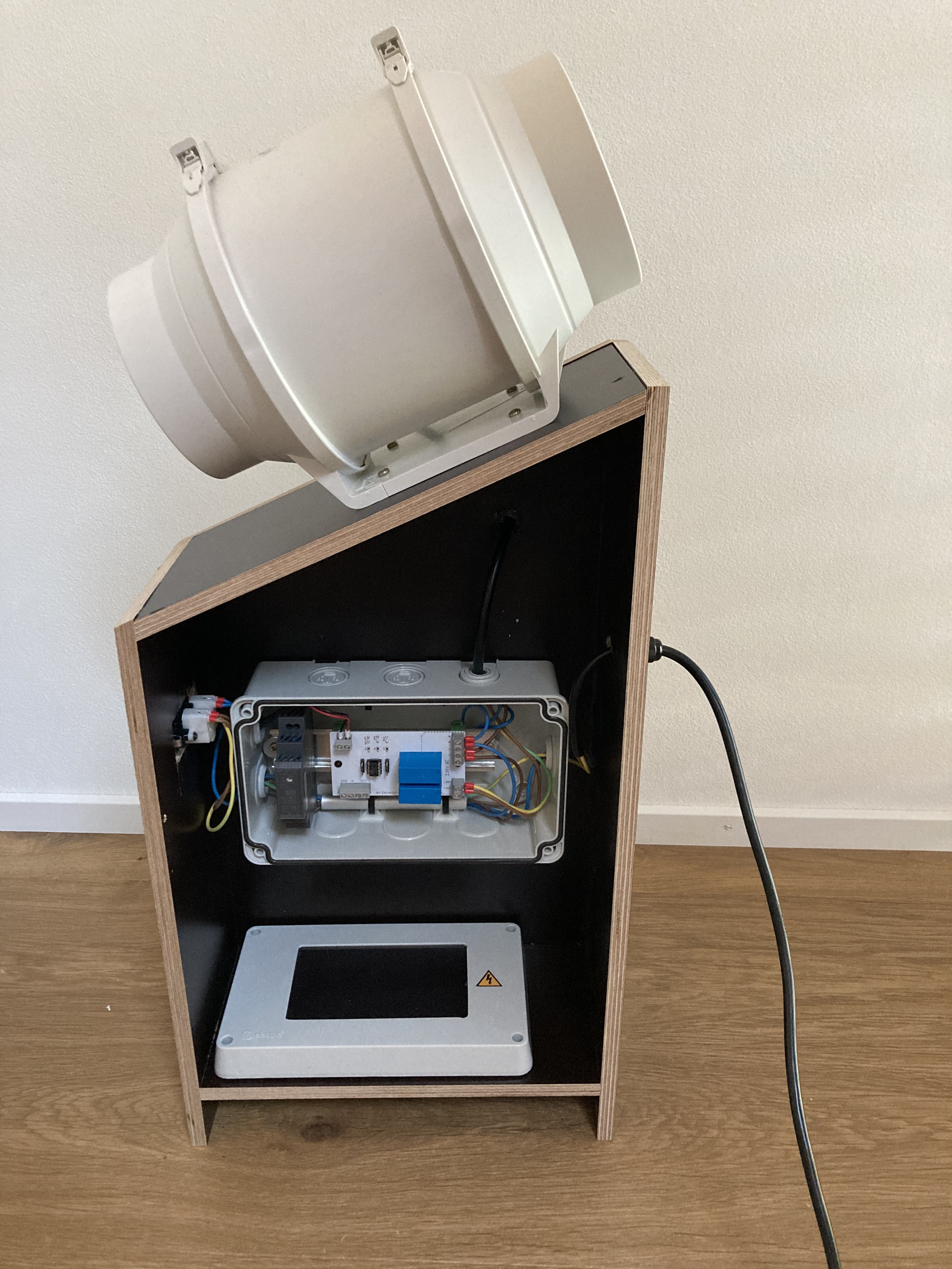
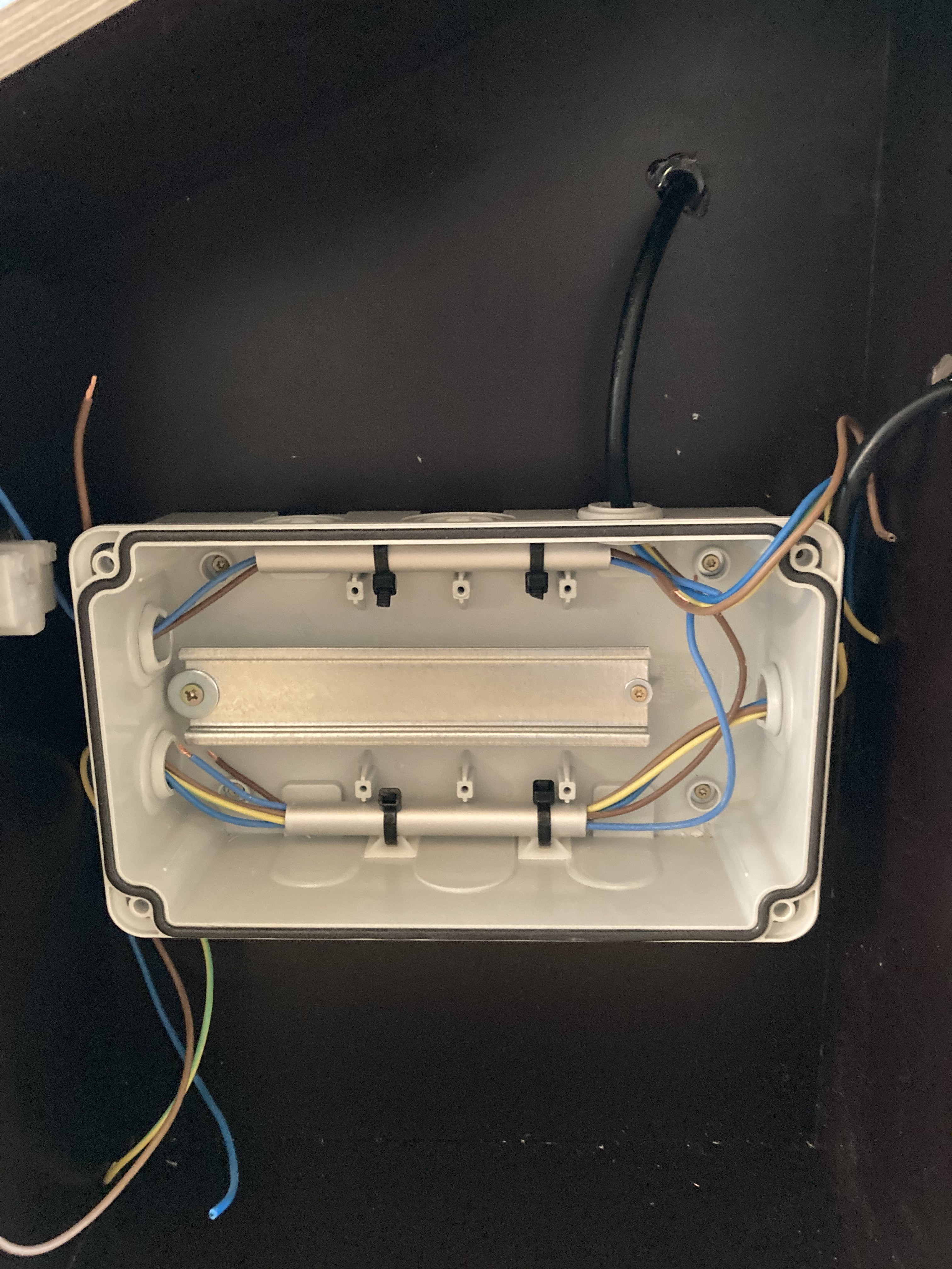
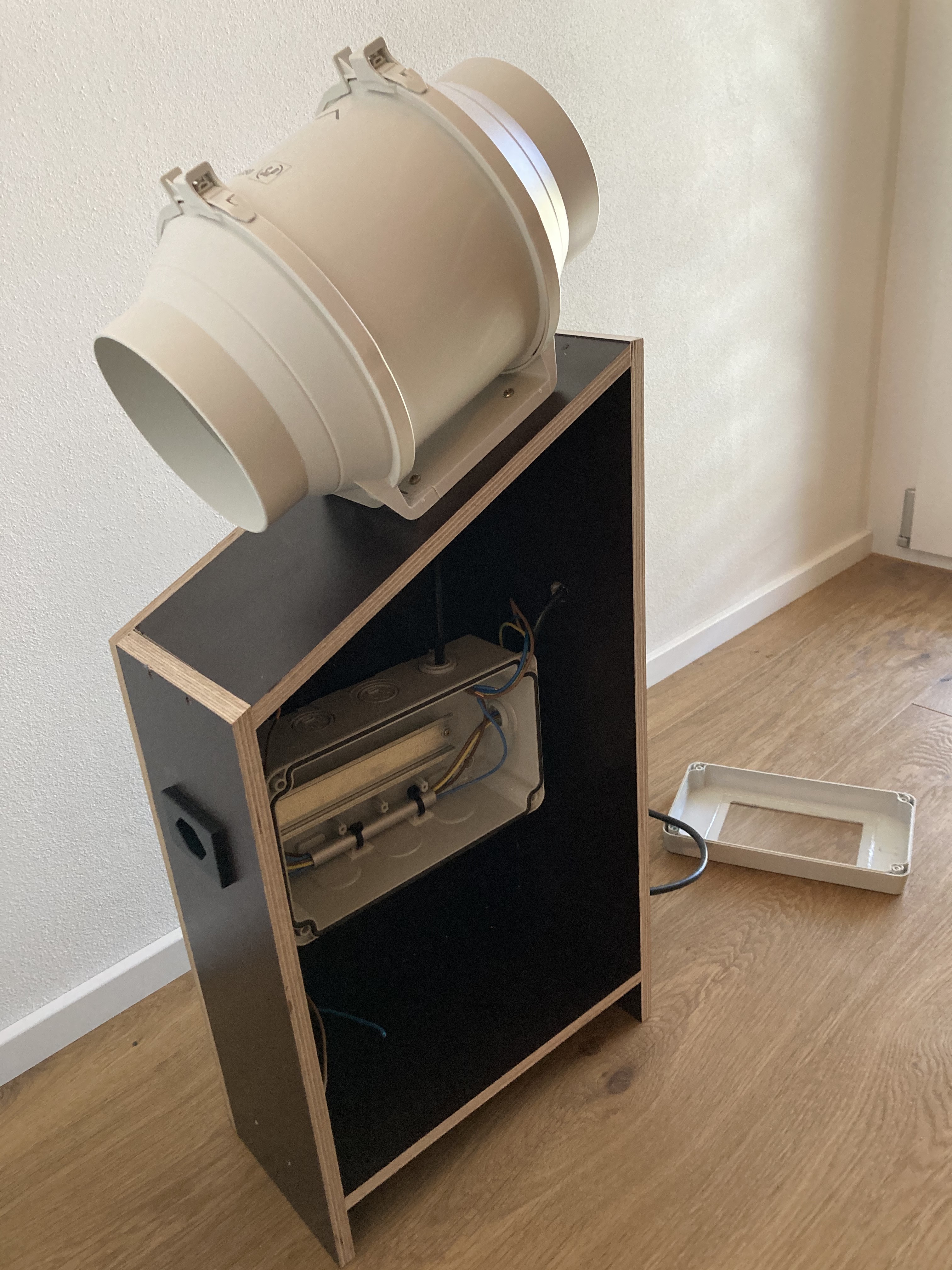
Enclosure, wooden support and wiring
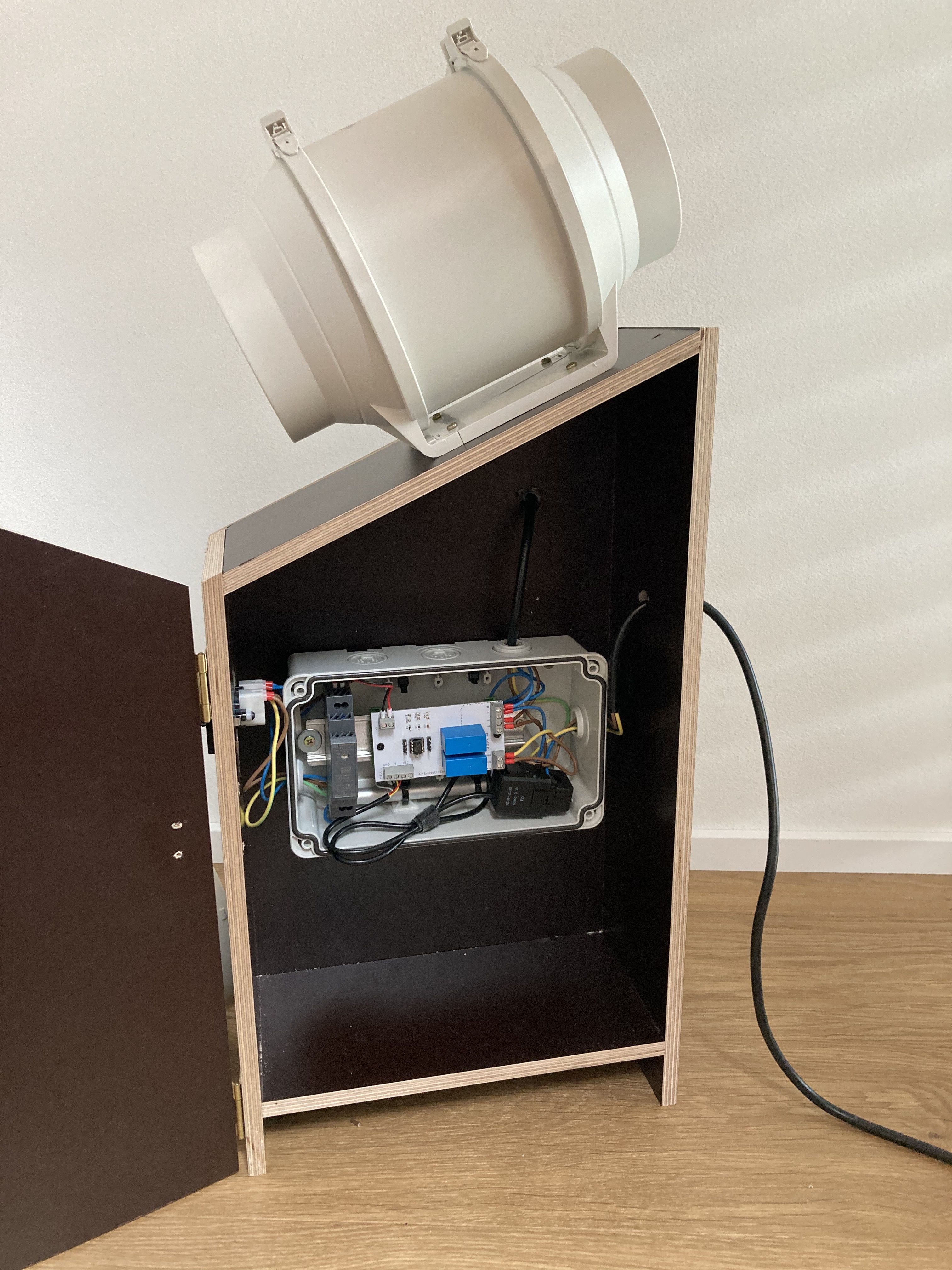
04/23/2021 at 19:42 • 0 commentsPlenty done for this week :
- Wooden support is almost done
- Wiring of high voltage wire has been done
- Junction box fitted with a DIN rail installed
- Air extractor has been delivered and mounted
Here’s some pictures of the progress
![]()
![]()
![]()
Air Extractor Controller for AC
A solution to extend a mobile AC exhaust duct with a two speed air extractor