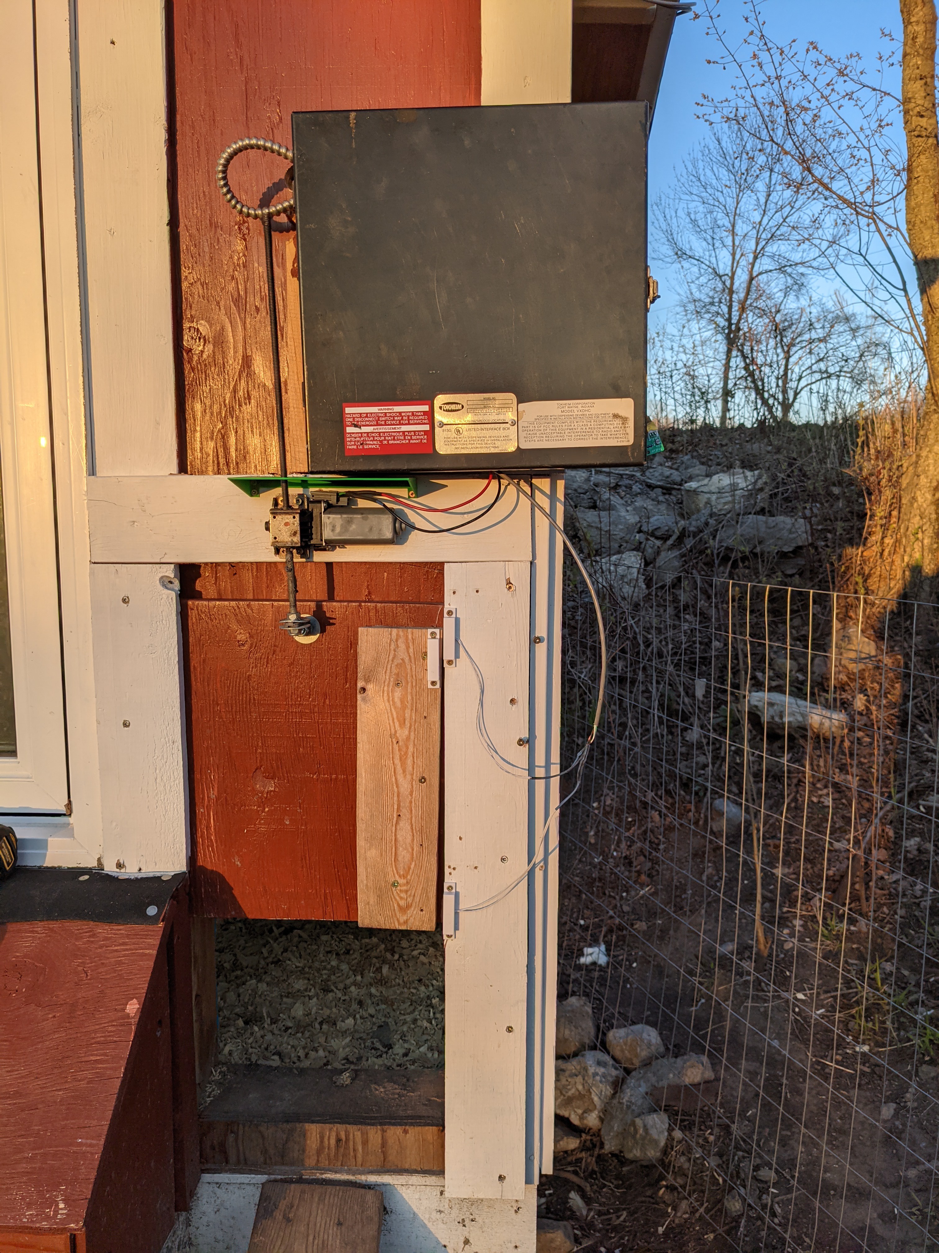
GOALS:
-Ease of installation and configuration for non-technical individuals.
-Multiple Power Options (wall wart mains power or 12-36V off-grid solar/wind/battery systems).
-Configuration settings saved in case of power-outage.
-Wi-Fi connectivity for remote monitoring and overriding of coop door.
-Camera for viewing inside of coop.
FEATURES:
COOP COMMAND MAIN BOARD:
-Pluggable Terminal Block connectors for all user-installed inputs/outputs.
-JST XH 5-pin for connection to CoopCam Wi-FI Camera Ad-On.
-DHT22 for interior coop temperature.
-DS18B20 for water temperature.
-GL5539 Photoresistor w/10K resistor voltage divider for daylight sensor.
-MAX3373 level shifting IC for Atmega-ESP32 serial communication.
-7805 "footprint" - Actually uses either one of the drop in footprint compatible buck convertors or my own "MEGA7805" buck converter that can output up to 3A cont.
-TI DRV8871 Motor Driver IC w/3.6A current cabilitity & voltages up to maximimum working voltage of CoopCommand.
-20x4 LCD.
-I2C backpack integrated.
-3 user input buttons.
-EEPROM for saving user settings.
-LayLight Relay for supplementing daylight hours to keep chickens laying even with less than 14 hours of Daylight.
-Ventilation Fan Relay for cooling the coop in the summer.
-Water Heat Relay for heating the water in the winter.
-ATMEGA328P in DIP configuration, easily programmed through Arduino IDE.
ESP32 COOPCAM:
-ESP32-CAM AI-THINKER based.
-Custom PCB for ESP-32-CAM to socket into, breaks out remaining GPIO's, breaks out serial header for programming and boot button as well as on-board bulk capacity (200UF).
-JST XH 5-pin Connector, identical pinout to mainboard side to allow cable to be plugged in either way.
-Wi-Fi connection through Blynk.
-Serial connection to main board.
BLYNK:
-Override door open or closed.
-Take a picture with the CoopCam and email it.
-Monitor door status (Open, Closed, Opening/Closing).
 hms-11


Hi. I was thinking about giving your project a go. I guess just go for the newest main PCB that has the I2C expander built in? For some reason i found your other repository for the coop(dash)command and had the PCB's made and then found out that there was no documentation and code avaiable. Ooops. The naming of the files are a bit confusing - what does "HVTaco" mean? Also there is a typo in "Integrated" - I also don't see on the boards where a 7805 (or switching variant) will go - this changed to an onboard switching regulator i guess? Please update the instructions. Regarding the case, the STL doesn't seem to match the PCB. The PCB has two buttons on top and one on the bottom. The case is different ...