-
Simulation
12/13/2023 at 23:37 • 0 commentsSimulation of a prospective ultra-lower power electronics system can help you confirm if a design is feasible. This step can also help prevent premature optimization and futile optimization of the wrong areas of the design.
The main goal of simulation is to understand the power used in various modes, how long is spent in each mode, and any energy harvesting that may be available. I have developed some helpful open source tools for this, which you can find on my other Hackaday.io project here:
Embedded System Power and Energy Estimation Tool
-
Examples
04/25/2021 at 19:26 • 0 commentsThis sections covers a wide range of example low power projects which can be useful references for your designs. Many of these are open source and have information on all of their components and clever system design and firmware used to reduce power consumption.
SOL: Long-term solar intensity sensingThis project is a solar powered pyranometer with an ESP32 providing Wi-Fi connectivity. Early versions used the ESP32 as the only microcontroller onboard, while newer designs have an STM32L4 for sensing and an ESP32 actin only as the Wi-Fi modem.
- Indefinite operation from 0.5W Seeed Studio solar panel
- Rechargeable 14500 lithium-ion cell
- ~6.2uA average in deep sleep mode
Ultra Low Power Feather Development BoardThis project was built as a challenge to see if I could build a Feather-sized development board which can operate indoors in active mode (i.e. without sleep modes), do some useful sensing, and be powered solely from onboard solar panels. It partially worked, but requires fairly bright lights. Of course, when sleep modes are used the power is vastly lower.
- 285uA in active mode, much slower in sleep
- SAML21 used as microcontroller, with accelerometer, barometer, and ambient light sensors
- SMD solar cells mounted on board
- Optional supercapacitor and Li-Po battery energy buffers
Thermoelectric Power Harvesting DemoThis was a project I built to test energy harvesting using common, low cost Peltier modules. I was able to run the ultra-low power feather development board from a 40F temperature differential.
MetaShuntThis is a tool I developed for power profiling ultra-low power systems.
LP Mini - Low Power Dev Board[Max.K] developed a low power Arduino compatible development board based on the standard Atmega328p microcontroller. By removing the typical power LED and using a more efficient regulator, the sleep current was reduced to 2.8uA.
Ultra Low Power thermometer[Miroslav Hancar] built this thermometer with an always-on screen, powered by a CR2032 coin cell battery or a very clever "solar 2032", which requires ~3uA in operation.
Low Power ESP32 Handheld[Max.K] built this low power device with a 2.7" always on Sharp memory display that uses an ESP32 and achieves current consumption of ~56uA.
Ultra-Low Power LiPo Charger via Energy Harvesting[Kris Winer] built this breakout board for the TI BQ25504 Li-Po battery charger. It is now available for purchase on Tindie.
STM32L4 Sensor Tile[Kris Winer] developed this low power sensor platform around the STM32L4 microcontroller which acheives average current of ~100uA while "smelling and hearing."
Ultra Low Power RF Node[Charles] developed this "universal" Arduino sensor node which can interface with a wide variety of sensors, has wireless capability, and can run from a few different battery types.
-
Select Exceptional Components
04/25/2021 at 18:23 • 0 commentsThis section covers the most impressive components I have come across, all with extremely low power consumption. In reality, for most ultra-low power applications, you really don’t need to go this far. If you are using a rechargeable battery, the self discharge will be multiple orders of magnitude higher than the power consumption of these components. But, if you need to hit a very low power spec, consider these parts.
MicrocontrollersThe first thing to note is that it is very difficult to compare microcontrollers to each other and determine which one is lower power without knowing the application. Many microcontrollers designed for ultra-low power have a wide variety of power saving features, some of which are applicable, while others are not. This section will not compare the microcontrollers to each other, but rather will point out some useful features to consider
Texas Instruments MSP430
The TI MSP430 family is commonly known for its ultra-low power performance. The family has a wide selection, many of which are tuned for a given application. There is not enough time to dig into many of them, but I will focus on one example, the MSP430FR2355:
- 142uA/MHz in active mode
- Uses FRAM for memory, which can be overwritten effectively indefinitely and is non-volatile
- 42nA in shutdown (LPM4.5) mode with I/O wakeup
- 620nA in LPM3.5 with RTC running
- Minimal current variation over temperature
Microchip ATSAML21
A close cousin to the Arduino-compatible SAMD21, the SAML21 has a 32-bit ARM Cortex-M0+ core and a wide variety of useful low power features.
- Can run in active mode at 4MHz at 285uA
- Down to 35uA/MHz in active mode
- ~1.2uA in standby mode with all SRAM maintained and RTC running
- ~530nA in backup mode with RTC running
ST STM32L4
The STM32L4 family of low power microcontrollers have an ARM Cortex-M4 core with FPU and a number of low power features.
- 84uA/MHz in active mode
- 8nA in shutdown mode with I/O wakeup
- 280nA in standby mode with RTC
Ambiq Apollo 3
The Ambiq Apollo 3 is used within Sparkfun’s Artemis platform. They have ARM Cortex-M4 cores with FPU, as well as BLE wireless communication.
- 6uA/MHz in active mode (though typically locked at 48MHz operation)
- 1uA in deep sleep with RTC
Voltage RegulatorsTexas Instruments TPS63900
The TPS63900 is an ultra-low power buck-boost regulator with very low quiescent current and high efficiency across a wide range of current output.
- 75nA quiescent current
- >90% efficient at 10uA
- >80% efficient from 1uA-400mA output
Microchip MCP1810
The MCP1810 is an ultra-low power LDO regulator with very low quiescent current.
- 20nA quiescent current
- 1nA shutdown current
SensorsAnalog Devices ADXL362
The ADXL362 is an ultra-low power accelerometer with very low power performance compared to its competitors. Note however, that its accuracy and bias are relatively poor.
- 1.8uA at 100Hz data sampling
- 270nA on “wake-on-shake” mode with ~6Hz sampling
OthersMicro Crystal Switzerland RV-3028-C7
The RV-3028-C7 is a RTC module with an I2C interface, extremely low power consumption, and high accuracy.
- +-1ppm @ 25C
- 45nA @ 3V
-
Measurement & Validation
04/25/2021 at 18:18 • 0 commentsSo you’ve selected components with low power, developed some firmware, and you want to know if your device is consuming as little power as expected. This is more difficult than you might expect. First, the power consumption in ultra-low power mode can be so low that most multimeters will not measure it accurately. As mentioned previously, active mode can easily consume 15,000X more power than in low power mode, so measuring data through more than four orders of magnitude can be very difficult. The shunt in a multimeter in its uA current range will be high enough that the burden voltage during active mode could be very significant and prevent correct operation. There are a number of tools that help with measurement and validation, roughly split between whether they work in just steady-state modes or if they can measure data through wake cycles.
Steady State Measurement Tools
Power Profiling Tools- Built into development boards
- Joulescope
- Otii Arc
- Nordic Power Profiler Kit II
- Angler Circuits ZS-2102-A IOT Power Profiler
- (Shameless Plug) MetaShunt
-
Energy Harvesting
04/25/2021 at 18:11 • 2 commentsThe reduced power requirements of ultra-low power systems enables the use of energy harvesting to extend battery life, potentially indefinitely. This leads to the question: How does one design an energy harvesting system? The first step is to understand the device’s average power consumption. For indefinite operation, this is then the minimum required average power generation of the energy harvesting subsystem. For intermittent sources such as solar panels, the system should also be designed with enough energy storage buffer that it can run for significant time without any power generated. In many parts of the world it is not uncommon to have two cloudy weeks or more in a row, which could reduce the power generated by 5X or more. The battery should be sized to survive events such as this.
Another mantra to understand for energy harvesting is that efficiency does not matter. All that matters is exceeding your average power and having a large enough energy buffer. The power from energy harvesting is free, so don’t feel like you need to extract it all. There are a number of cases that I will show in which intentional efficiency reduction can reduce cost, simplify the system, and make it more resilient to long time periods without full power energy harvesting available.
Solar PowerThe simplest, lowest cost, and most reliable form of energy harvesting is the use of solar photostatic cells, especially if the system is used outdoors. If indoors, solar power can be used, but the available power is far, far lower. However, even if outdoors, scaling an appropriate solar panel has certain pitfalls. Solar panels are typically rated with a peak current, peak voltage, and a peak power. This rating assumes the panel is perpendicular to the sun, under direct sunlight. If shaded or angled relative to the sun, the peak power will be lower. The average power generated can be calculated using a capacity factor. Usually used to describe grid-scale power plants, the capacity factor is the actual energy produced over a certain time divided by the energy that would be produced if it ran at full power during the entire time. For example, if a coal power plant ran for 4 days at full power, then was down for 1 day for maintenance, it would have a capacity factor of 0.8. Industrial solar photovoltaic plants have capacity factors typically ranging from 0.12 (in places like Michigan or Massachusetts) to 0.33 (in deserts of southern California). There are many online tools for estimating available solar power in your area, such as this database from NREL in the USA. It can be helpful to find an installation near you, and use its performance as an upper bound of what you can expect. These industrial-scale installations are well maintained, not shaded, and carefully oriented to maximize power, so your device will likely do worse. It is not a reliable approach to "look outside" and judge if it is typically sunny. The human eye is a very poor tool for estimating the potential power available to solar panels. With a roughly logarithmic response, the human eye is good at seeing in dark places, but fails to see that the power available in shade can be an order of magnitude or more less than in direct sunlight. Depending on the solar panel, partial shading can be just as detrimental as full shading. If possible, the temperature of the solar panel should be limited since solar panels are noticeably more efficient at low temperatures.
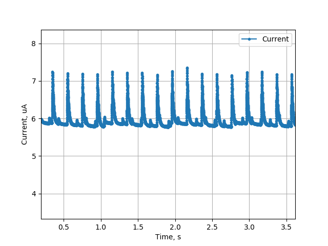
Just because a solar panel can provide a certain amount of power, this does not mean that amount will all be used to charge your battery. There are a few pitfalls to be aware of that can cause a drastic mismatch between the peak power production and the charging power. The first is the amount of power used by the charger itself. This is usually only a concern for very low power systems and small solar panels. Consider my SOL project. In deep sleep, it requires only ~6.2 uA on average, as shown by the profile below. It uses the TP4054 linear lithium-ion charger while in deep sleep to charge its battery. Because it is a linear charger, roughly 30-40% of any input power will be burnt off as heat within the charger. Furthermore, the TP4054 requires roughly 150uA to operate its internal circuitry during charging, which is >24X the power of the rest of the system. Because this power comes from the solar panel though, it does not affect battery life, but does limit maximum charge rate.

The other mismatch between maximum produced power and charging power is due to impedance matching, or lack thereof. Consider again my SOL project. While the solar panel is rated to a maximum of 550mW at 5.5V and 100mA, I have configured the charge current to be a much lower 15mA. This significantly limits the maximum power that SOL would ever charge at to ~60mW. However, there is a very good reason for this. If a linear charge controller attempts to charge at a higher rate than the solar panel can provide, the voltage on the solar panel can droop. If it droops below the battery voltage (plus some offset required by the charger), it will not be able to charge at all. Therefore, this limited charge current ensures that the system can charge much more often, making it more resilient to cloudy days.
An improved approach, albeit typically more expensive, is to use a Maximum Power Point Tracking (MPPT) charge controller. These are switching charge controllers that perform impedance matching at all times in order to maximize the charging efficiency from a solar panel. Therefore, they are not set at a fixed charging current, but rather change throughout the day based on available power. Parts such as the ADP5090 and MAX20361 offer extremely low quiescent current below 1uA. Others require more power to operate, such as the SPV1040 which requires 60uA.
When designing a system that uses solar power for energy harvesting, consider optimizations that can reduce power consumption during times when the panel is less effective or ineffective. For example, my project SOL is a pyranometer so measurements at night or while covered with snow are not useful. Therefore, the sleep time between samples changes adaptively depending on the available sunlight, and is extended significantly at night to reduce power consumption.
A solar powered system will often be installed outdoors. If so, be aware of the limited temperature range at which lithium ion batteries can be safely charged. It will vary somewhat by the specific battery, but 0-45C is a typical range of acceptable charge temperature. A well designed system should have temperature measurement and charger disable capability. It should also be designed for either:
- Low enough power that there is no need to charge during peak power times
- Good thermal management ensuring it can charge more often
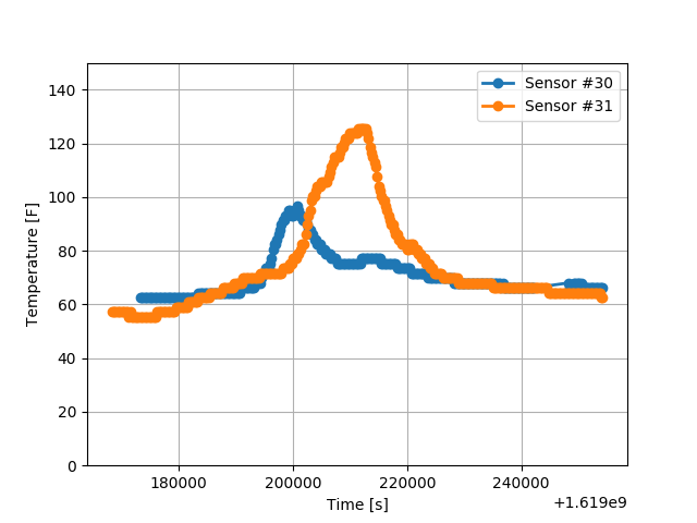
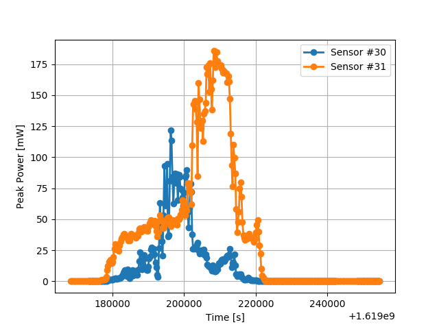
You may be surprised at how easy it is for a device to reach >45C in direct sunlight, even if the ambient temperature is far different. Worse still, a high temperature correlates with significant solar power available, so the system has to disable charging during the highest power times. Consider the data shown below. This is the internal temperature and available solar power for two SOL devices. Both are set up indoors, in two different windows in different parts of Atlanta, GA in April. Although the ambient temperature for both is controlled, Sensor 31 easily reached >45C (113F) temperature during the highest power portion of the day. As is clear from the data, this was a partly cloudy day, it isn’t even the summer, and the ambient temperature is roughly room temperature since it is installed indoors. If this were installed outside, it would be significantly hotter.


If the solar powered system is meant to operate indoors, prepare for a much more significant challenge. The light intensity in an office can easily be 1,000X less than direct sunlight. Worse still, most solar panels are tuned to operate in sunlight’s spectrum and are quite inefficient with artificial lighting. There are specific solar cells (typically amorphous silicon cells) tuned to indoor lighting that you should consider, such as Panasonic’s AM-1819CA. This example can provide 7uA at 3V under 200 lux fluorescent lights, which is far, far less than an equivalent sized monocrystalline cell in direct sunlight. My indoor-solar powered Feather development board could kind-of operate indoors without sleeping, but with significant limitations (though to be fair that was more of a design challenge than a practical device).
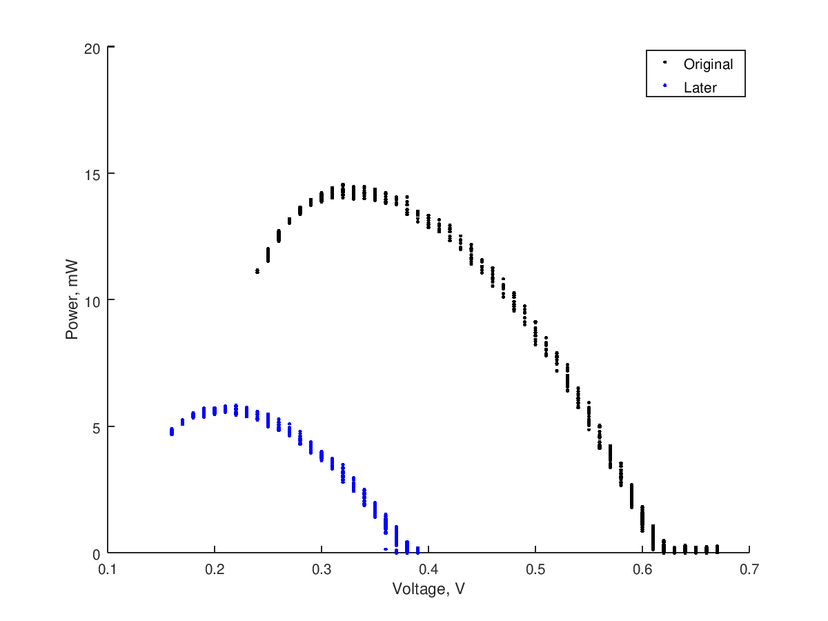
Thermoelectric GenerationNASA's Curiosity and Perseverance do it, so why can’t you? Thermoelectric energy harvesting is tempting to many developers. A simple, low cost Peltier cooler can be operated in reverse, becoming a (very inefficient) Seebeck Thermoelectric Generator (TEG). I have done some experimentation with these, and the summary is that while it is possible to use them, you should use solar panels instead if at all possible. The available power at a roughly 40F temperature differential was noticeable, at ~15mW. However, the voltage was quite low, requiring some specialized electronics that can boost <0.5V up to more usable levels. Worse still, the available power dropped off quickly as the temperature differential equalized. With better thermal management, this could be improved. The image below shows the power vs. voltage curve for a TEG with ice on one side, and an aluminum heatsink in room temperature water on the other side. After a few minutes, the available power dropped dramatically as the temperature equalized.

Vibration/Piezoelectric HarvestingPiezoelectric materials can produce a voltage in response to vibration or pressure, and are often used in sensors. In theory, they can also be used for vibration energy harvesting. Some devices and demos have been built that succeed in generating useful amounts of power from vibration. However, they often have abysmal efficiency and/or very expensive electronics to do so. Although I’d love to see more projects leverage this as a design challenge, you are better off using solar power if possible.
Wind PowerWind power is a significant and growing portion of the world’s renewable grid-scale energy production. However, it seems to be a much less common source for small-scale energy harvesting. There are a few challenges:
- Unlike solar, thermoelectric, or vibration energy harvesting, it has moving parts, making waterproofing and reliability more challenging
- Wind power is much more efficient at large scale and higher altitude
- There aren’t any COTS small-scale, low-cost wind turbines (that I know of)
Nonetheless, I’d love to see more projects with wind power harvesting at the small scale, even if efficiency is poor.
-
Energy Storage
04/25/2021 at 17:47 • 2 commentsAn important part of an ultra-low power design is the energy storage device. This section covers a number of commonly used energy storage devices, their typical limitations and pitfalls, and applications that they excel at. It is not meant to be a definitive explanation of battery technologies, as that information is better described elsewhere.
Primary Lithium Coin Cell (Manganese Dioxide Lithium)
Perhaps the most commonly used battery family for ultra-low power applications is standard primary (i.e. non-rechargeable) lithium coin cells. They provide high energy density and very low self-discharge rates. Typically rated at 3V, they can provide voltage at typical ultra-low power electronics levels without the need for multiple batteries or a boost converter (which might be needed for a 1.5V alkaline cell.) The main limitations of these batteries are that they cannot be recharged (so energy harvesting is not possible) and they have very limited discharge current capability. For example, the Renata CR2032 has a maximum continuous discharge rating of 3mA. To achieve the quoted energy capacity, a lower current of 0.2mA must be used. For many designs, this is simply not enough power.
Lithium Thionyl ChlorideLithium thionyl chloride batteries are also non-rechargeable and have very low self-discharge rates. They have excellent performance over a wide temperature range and are among the highest energy density batteries available. Correspondingly, they are expensive. For the developer, it is worth noting that they have extremely flat discharge curves, so it is not practical to estimate remaining battery life simply from a voltage measurement. They can provide significantly more power than Manganese Dioxide Lithium coin cells.
Lithium Ion Cylindrical CellsThe commonly used 18650 battery is a lithium ion cylindrical cell. These are also available in other sizes, such as the AA-sized 14500 and the AAA-sized 10440. They are rechargeable, but have lower energy density than lithium primary cells. They also have much higher self-discharge rates, up to ~10% of the capacity per month. These batteries can provide a lot of power, although some cells are designed for power and some for energy. Note that batteries sold from non-reputable sources often vastly overestimate their capabilities.
Alkaline BatteriesThe common AA or AAA alkaline battery can also be a reasonable choice for ultra-low power electronics. These batteries are cheap, non-toxic, have low self-discharge, and relatively high power output. Over a long period, they can leak and corrode the electronics they are installed within, so they may not be a good idea for devices with multi-year battery life.
SupercapacitorsAlthough the energy density of supercapacitors is far lower than all of the batteries here, they do have certain advantages. They are simple to charge using energy harvesting technologies and have very high power output capability. They are also relatively expensive and some have high self-discharge (leakage). Because they are not batteries, they do not have a flat discharge curve. It is usually only possible to use some portion of the energy before the voltage drops below a usable level.
Closing ThoughtsWhen selecting an energy storage device, be aware of the operational temperature of your device. Batteries are significantly affected by their temperature, and rechargeable batteries can only be charged within a relatively tight range. If the design will be outdoors, be aware that the temperature can be far higher than ambient if under direct sunlight, but the low-end of temperature will be limited to ambient.
-
Typical Operation
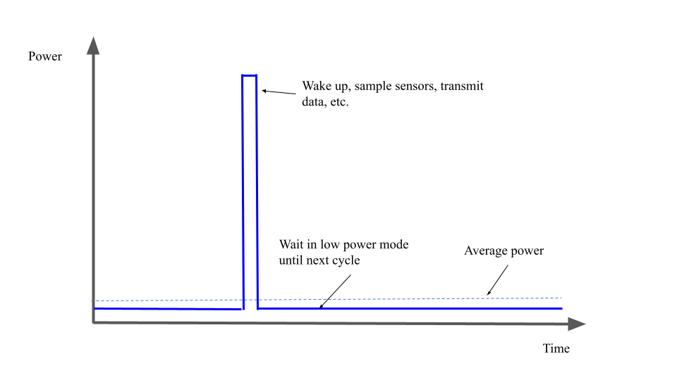
04/25/2021 at 17:40 • 0 commentsIn many designs, “ultra-low power” is a bit of a misnomer. More accurately, most designs are ultra-low average power. While these devices may also have low active power consumption, the real power savings are achieved by operating most of the time in a lower power state. The figure below shows a nominal plot of the power used in an ultra-low power device. The device periodically wakes up, performs tasks such as sampling data from sensors, transmitting it over a wireless network, and then re-enters its low power mode as quickly as possible. If the duty cycle is high enough, this can result in average power consumption that is very close to the power consumption in its low power mode.

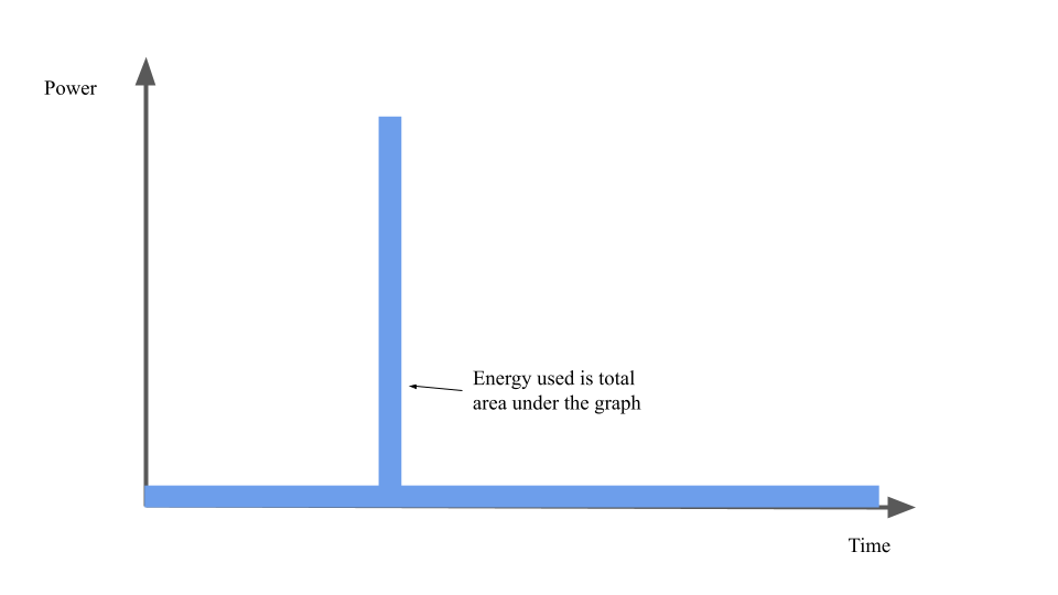
While “power” and “energy” are sometimes colloquially used as interchangeable, engineers know they are not. Energy used is equal to power used over time, and therefore the total energy used throughout this example is equal to the area under the graph. This is shown in the figure below.

While this plot is a simple way to show the data, it is misleading. It appears that the ultra-low power mode consumes roughly 10% of the power needed in active mode. In reality, the gap between active and sleep modes is often far wider. For example, the Microchip ATSAMD21 (used on many Arduino compatible development boards) requires roughly 4-7mA in active mode while running at 48MHz. In standby mode, it requires roughly 1,000X less power. This gap is even wider for the wireless-enabled ESP32. With Wi-Fi connected, the ESP32 can easily require 150mA or more, and can drop down ~15,000X to 10uA in deep sleep! Neither of these components are really ultra-low power microcontrollers either; those that are can have significantly lower-power low power modes.
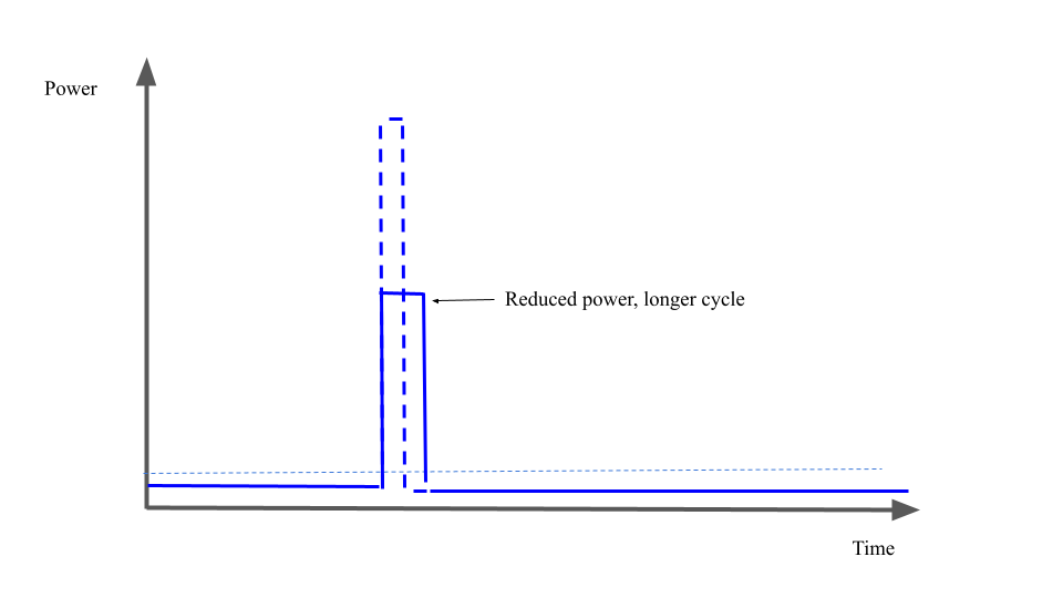
With this gap in mind, it is useful to consider at a high level how a designer might reduce the average power of their design. Consider a simple design that consists solely of an ATSAMD21. Every 10 seconds, it wakes up and does some processing, If this processing requires 100ms, it will be in low power mode for 99% of the time. This results in an average current of ~54uA. Due to the enormous power difference in the modes, >92% of the total energy is used during the 1% of time spent in active mode! Therefore, the developer’s focus should usually be on reducing the energy used while in active mode. Clearly, this can be done in two ways: the power used or the time spent can be reduced. Often, these can be related. Most microcontrollers can operate at various frequencies. They will typically consume more power at higher frequencies, but of course will then be slower. The image below shows the potential power profile change when lowering the active mode frequency significantly.

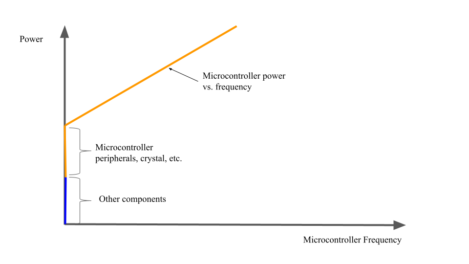
Although reducing the operating frequency can reduce the power used by the microcontroller, this is typically only an effective change if the time spent in active mode is not CPU limited. For example, if the active time required is due to the sample time of some sensor, the CPU may simply be waiting for data for most of the active mode section. In this case, reducing the CPU frequency can reduce overall energy use. The image below shows why. Even with the microcontroller CPU frequency set very low, there is a base power consumption by other components and microcontroller peripherals that is unaffected. By lowering the frequency, this base power consumption is consumed over a longer time. Of course, in reality many microcontrollers have numerous internal clocks running at configurable frequencies. The summary is that the microcontroller should typically perform its active mode operation as quickly as possible, then re-enter low power mode.

Introduction to Ultra-Low Power Electronics
An introductory guide to designing ultra-low power electronics for makers
