How It Works
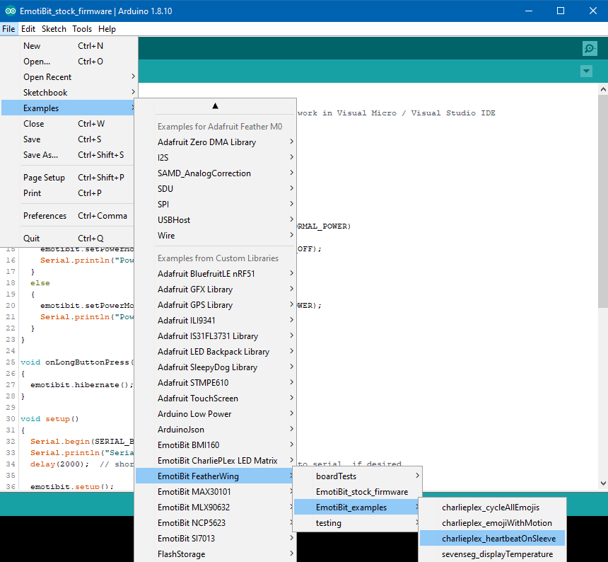
- The EmotiBit firmware library communicates with the onboard PPG sensor (MAX30101) via I2C to get PPG data. The sensor has 3 different wavelengths that can easily be accessed by tweaking the stock example to provide different cardiovascular information.
Code snippet below:
void loop() { emotibit.update(); size_t dataAvailable = emotibit.readData(EmotiBit::DataType::PPG_INFRARED, &data[0], MAX_DATA_SIZE); // do something cool with your data! } - The raw PPG data is then passed through a simple first-order lowpass (LP) IIR digital filter. This filtered signal acts as a threshold for the crossing detector (discussed next).
- The crossing detector is created by comparing the raw PPG signal with the LP filtered threshold signal.
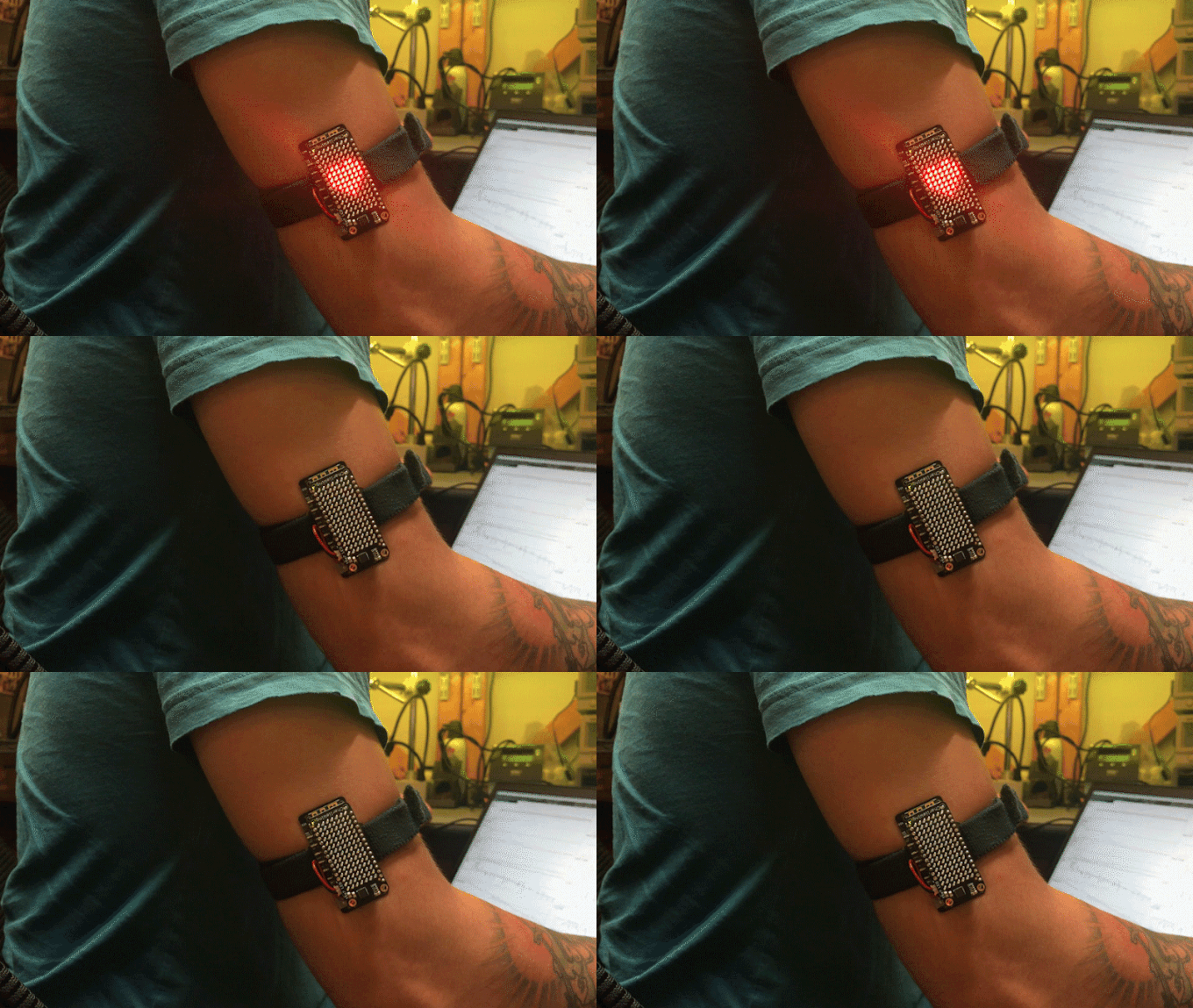
If the raw PPG signal goes above the threshold, the CharliePlex led matrix is turned ON. Conversely, when the raw PPG signal goes below the threshold, the display is turned OFF.
Above is a screen capture showing the trigger for the led matrix as the green square wave signal. The raw PPG signal is shown in blue and the LP filtered threshold signal is represented by the red line. Note that this is also mathematically equivalent to using a high-pass filter with a zero-crossing threshold.


Tried this with a working Emotibit from their basic setup. But all I am getting is a serial error:
Setup failed: SD-card not detected.
Card is in place with correct config info..