 Yann Guidon / YGDES
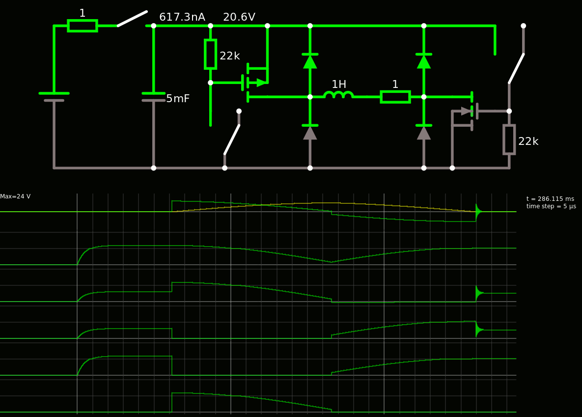
After playing with pen&paper, here I am looking at the more detailed behaviour and I got one first system that operates in 3 phases :
- load the tank capacitor
- when done, discharge the capacitor into the inductor by enabling the N and P MOSFETs
- when the capacitor is discharged, recover the energy by blocking the MOSFETs
The fact that the MOSFET are driven by the capacitor's value provides an avalanche effect because the lower the capacitor discharges, the lower the conductance of the MOSFET so the higher the reactance from the coil.
Here is the link to the sim if you want to play at home.
For now, the inductor is arbitrarily chosen to 1H and the tank has 4700µF. Circuitjs helps choose the tank capacitor's value. Here I can expect easily 4 to 5Hz. The period would depend on other parameters that could be controlled by a microcontroller or more analog parts... Some feedback is required though but I don't intend to make a pure analog Finite State Machine.
Discussions
Become a Hackaday.io Member
Create an account to leave a comment. Already have an account? Log In.