-
1Order Everything
Omc-Stepperonline: pretty straight forward just sign up, and order.
Maedler: is a site where we order many mechanical parts. These parts are universal and available on many sites. https://www.mcmaster.com/
Bearings: maybe it's locally available otherwise many sites are available for orderings these bearings, same goes for Timinig Belt, Pulleys, Retaining rings square axle, Circulair axle, end stops, MDF Plate.
Sheet Metal: https://metalscut4u.com/carbon-steel, https://www.247tailorsteel.com/nl, https://csmfab.net/
-
2Bucket
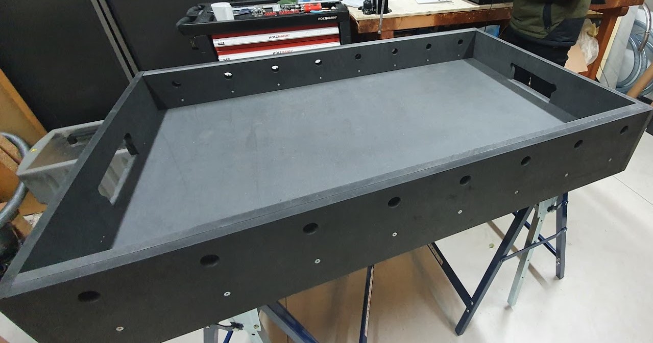
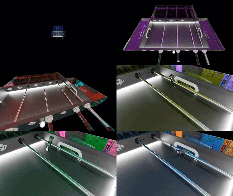
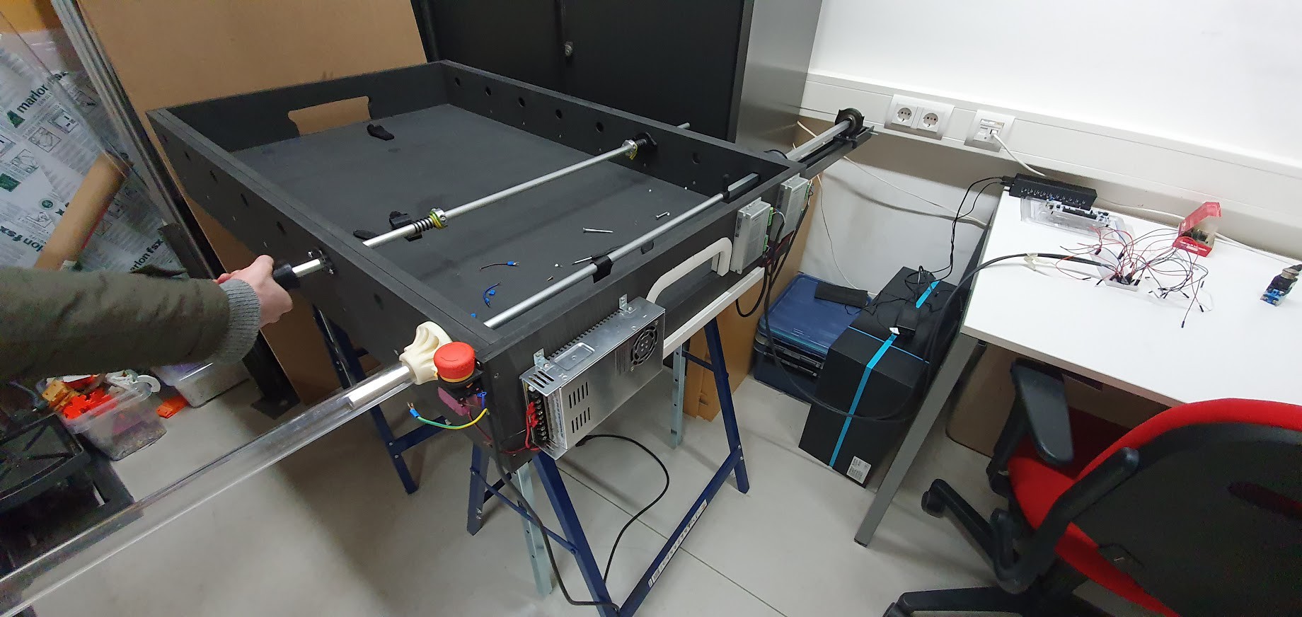
The Bucket is pretty straightforward, you get a wooden plank 18mm thick. you cut the required pieces out of it to make the field. We used a total piece of 344X122cm. And had something to spare. You need to be a little creative on the holes not everything is done for.
![]()
![]()
![]()
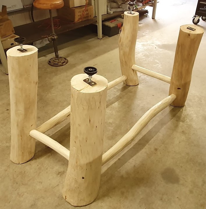
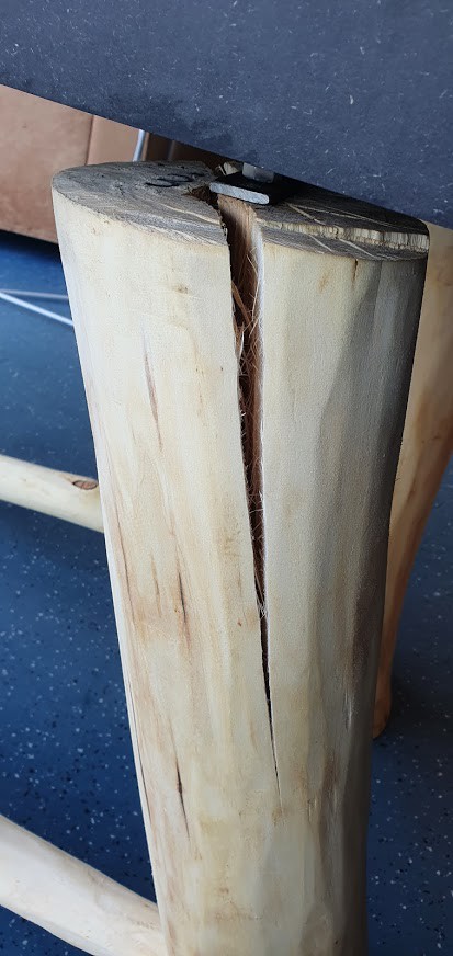
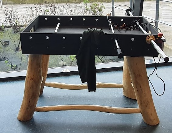
This undercarriage looks pretty cool. It was drenched with linseed oil. It had no time to dry.
![]()
![]()
![]()
-
3LRAM (Linear Rotational Axle Mechanism)
We thought about a rack and pinion system. Electromagnet system, only they're really expensive.
![]()
So we settled for something more simple.
![]()
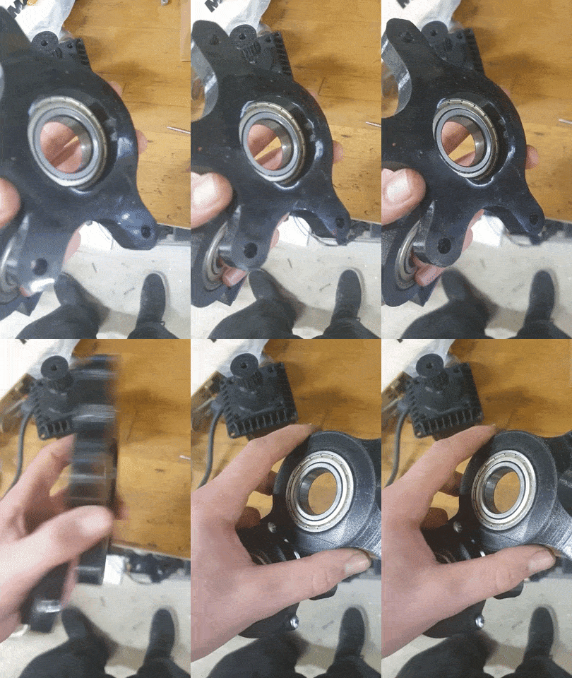
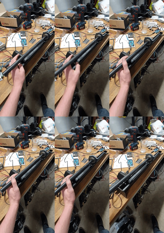
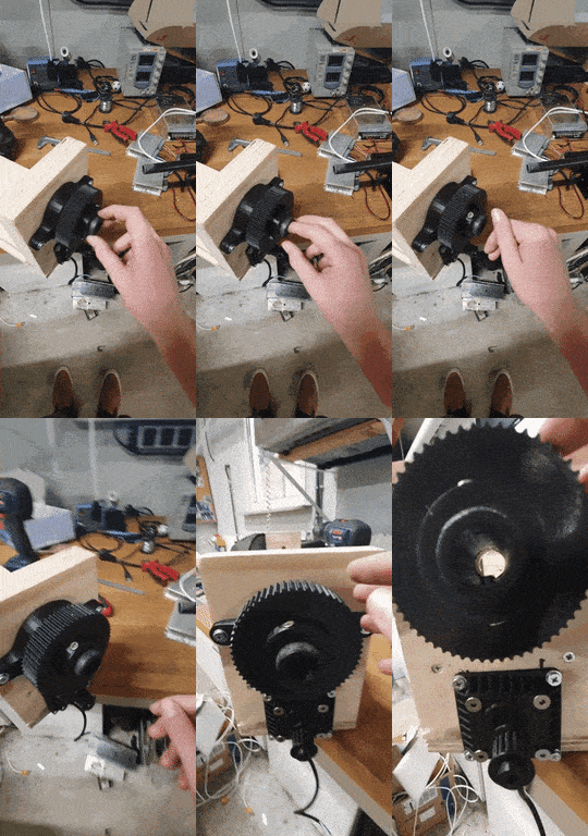
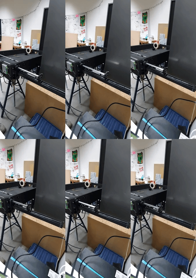
One part is a linear belt system where a slider is dragged linearly over an axis. there's a bearing clamped into the slider. Which allows for free rotation whilst the linear movement.
![]()
![]()
![]()
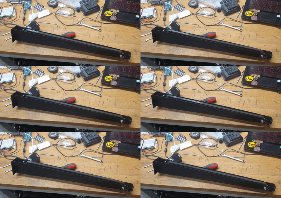
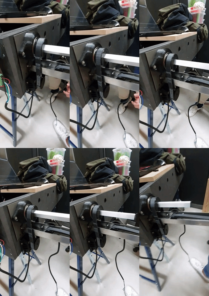
The inside was the first circular with a feather key inside it. The other part would slide through. The problem we ran into was that the friction was too high. So we used a rectangular aluminum extrusion with the same mechanical principle in mind, only a different shape to translate the force to.
![]()
![]()
![]()
![]()
-
4LCS (Light Coordinating System)
LCS: We did a couple of experiments, trying a field of lasers, white led, And IR. All didn't work well with us. So temporarily we're using a camera. Until we finish the system.
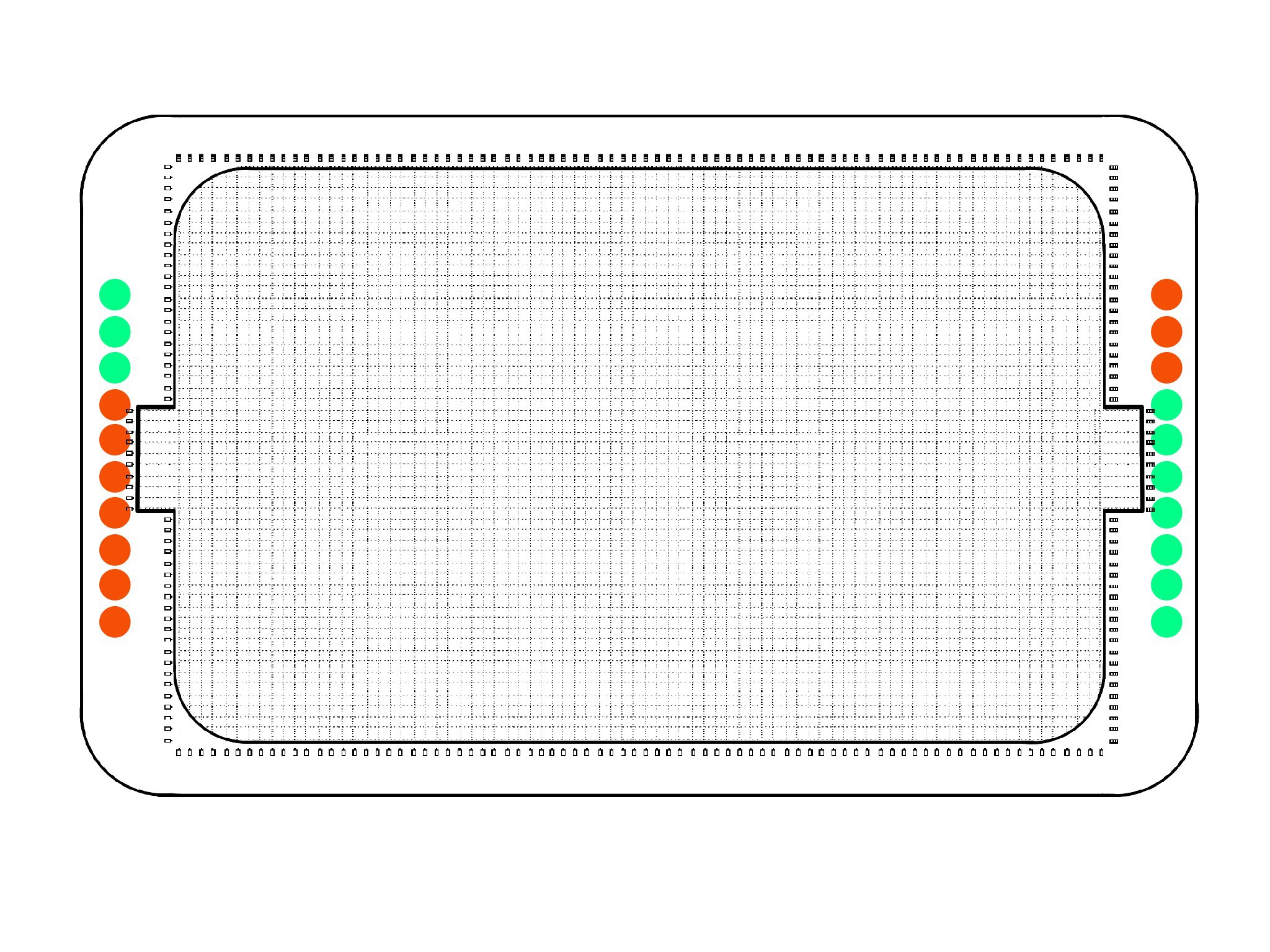
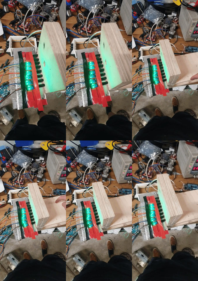
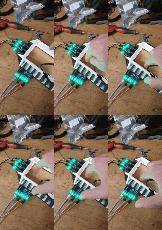
Grid System: We had in mind a grid of light on two perpendicular sides of the field on the opposite side there would be sensors that would detect any interruption of the light. With the interruption of light on two axes, you can calculate the coordinates of the ball interrupting the light field. In this way, we only have to put light and sensors contour of the bucket. If we would put a sensor for example under the field we would need a sensor on the whole surface of the field. That would be a difference of a factor 44,21. That means we would need 44 times more sensors if we would do it surface wise. If we would we want a precision of 8mm we would need sensors every 10mm, contour that would be 1200+700mm:10=190 sensors, in contrast, if we would do it surface wise it would be 1200x700mm:10=8400 sensors. With one ball in the field, it doesn't matter if you would use a contour grid system, however, if you want multiple coordinates of objects in the field and the objects cross each other on one of the two axes, you couldn't get the exact coordinates.
![]()
![]()
![]()
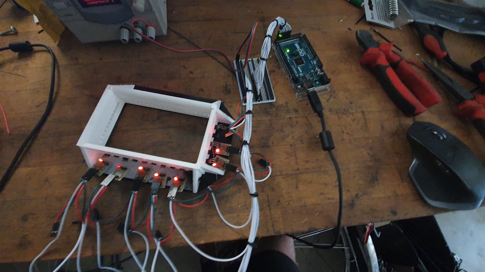
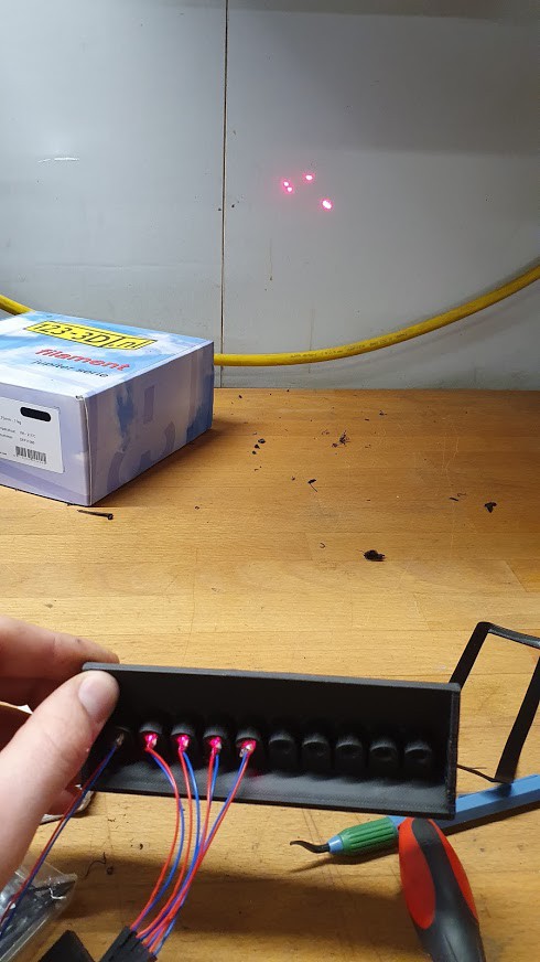
The printed structure holds the diodes parallel to each other, however, the light beams were not parallel to each other. To adjust every diode to hit the perfect spot across the field is not possible while reliable. So we had two options ditch the laser prototype or buy really expensive lasers. We went with ditch the lasers.
![]()
![]()
![]()
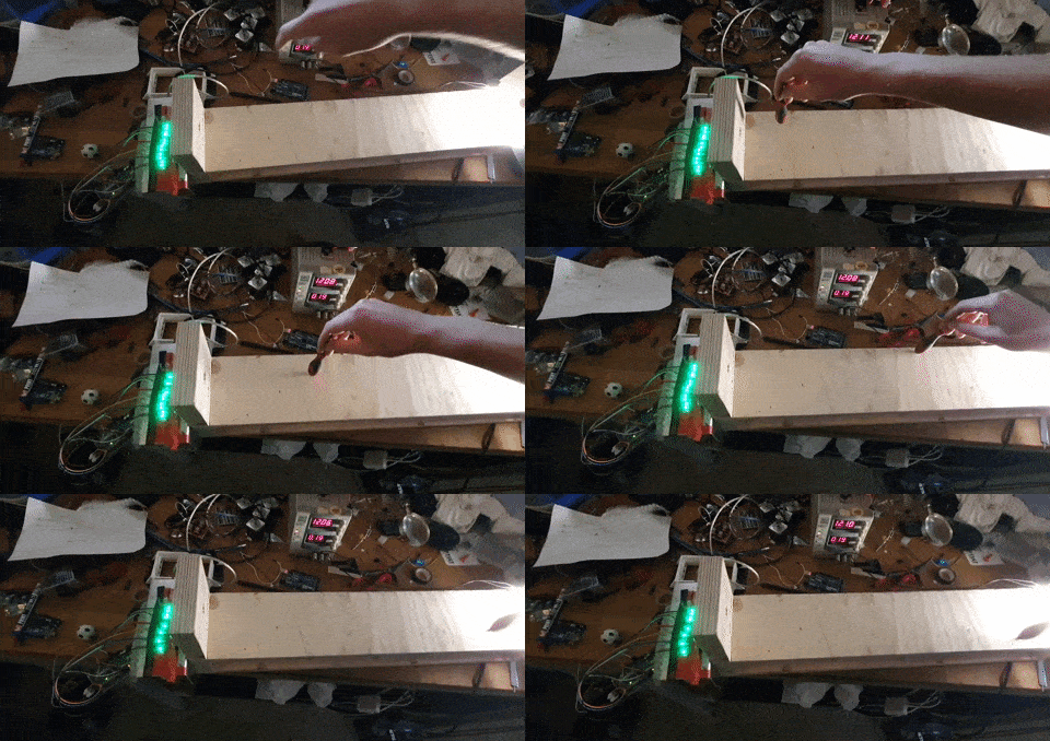
Next was white led, The nice thing about a White led strip is that the light emitted always shines right into the tubes where the sensors lie behind. The only problem was how farther the object is towards the light source the bigger the shadow, therefore the results were unclear. We tried to minimalize the shadow effect with long black tubes, which should absorb all the light the shines into the tube at an angle. Unfortunately, that didn't work as well as expected. Also, White Led corresponds with daylight on the EM spectrum, which makes it very vulnerable to changes in daylight. So we also ditched this idea.
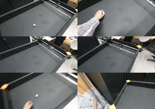
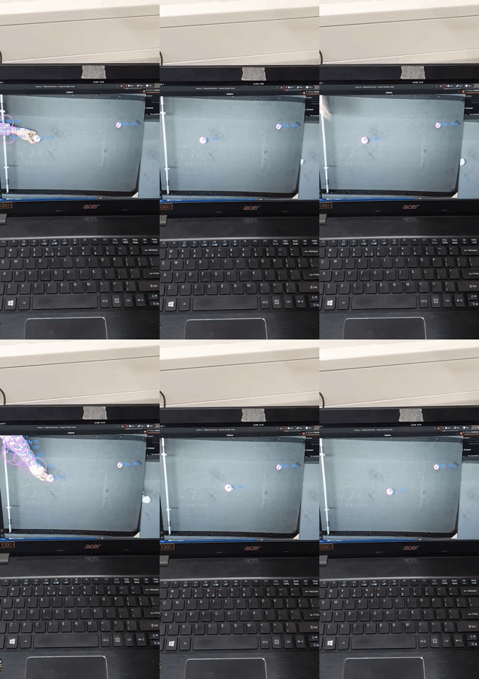
At this point, the LRAM was ready to test so we rushed the camera ball coordinator. This video shows a bit of how we used OpenGL with a circle detector to only detect the ball. Therefore the system is not vulnerable to the movement of the axes. The system still needs a calibration sequence to transform the perspective view of the ball into coordinates that more resembles an orthographic view.
![]()
-
5KOS (Knock Off System)
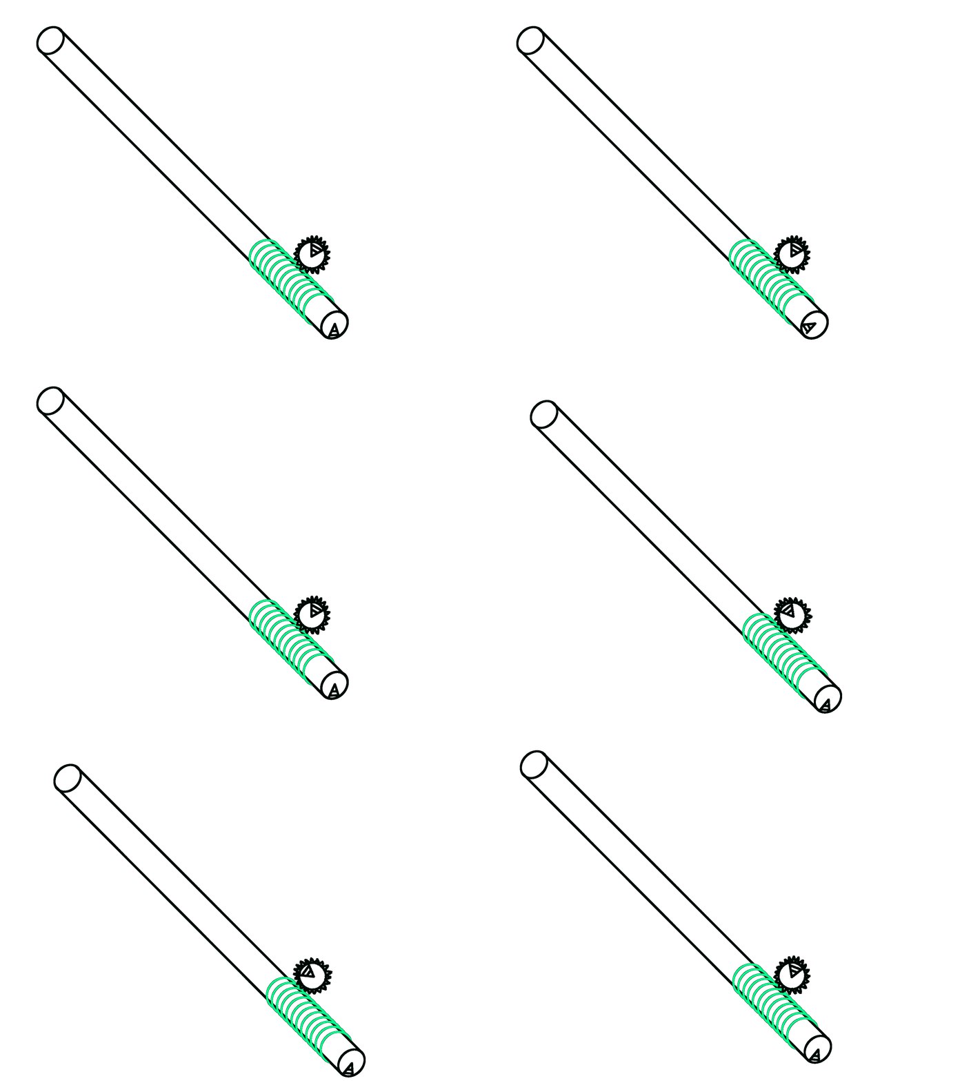
Here is a system that calculates the position and rotation of the human axes. We use 2 LADAR TOF sensors. One sensor is aimed at the outer circle, this sensor measures the linear position. Because this outer circle doesn't change its distance while rotating, the output value of the sensor stays the same. The other sensor is aimed at the spiral, this sensor measures the rotation by subtracting its value by the value of the outer sensor.
-
6SKYNET (RL System)
This part is still in development.
![]()
 Sixth_Nassau

Discussions
Become a Hackaday.io Member
Create an account to leave a comment. Already have an account? Log In.