 Peter Buchegger
-
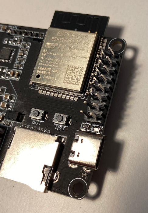
1Solder the pinheader on the PoE board
you need to solder the 2x8 pinheader on the upside of the PoE board like you can see in this picture:
![]()
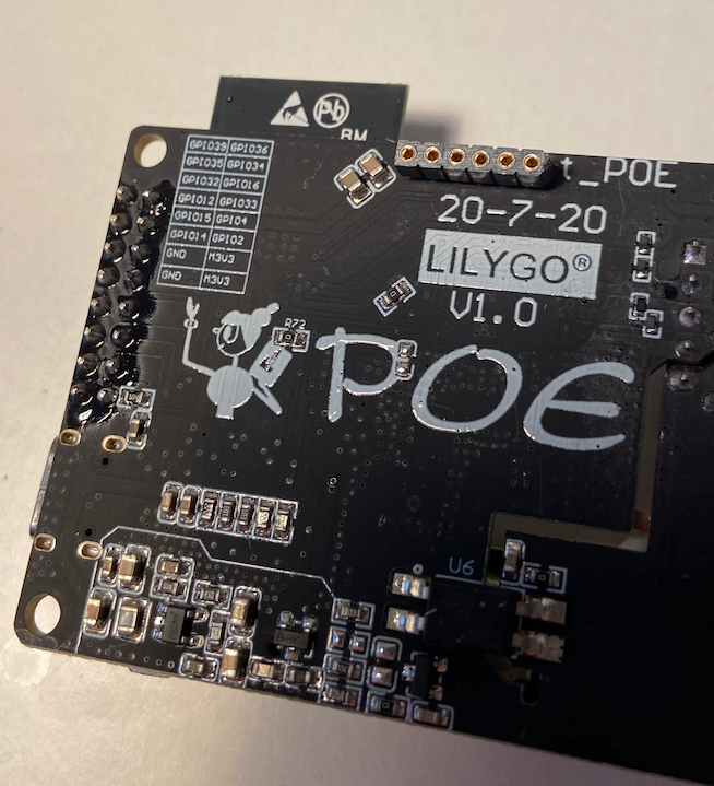
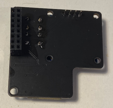
Now solder the 1x6 pinheader on the underside:
![]()
-
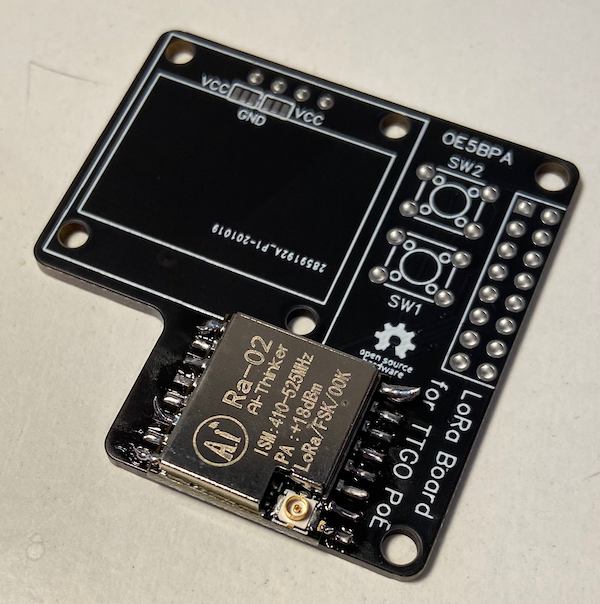
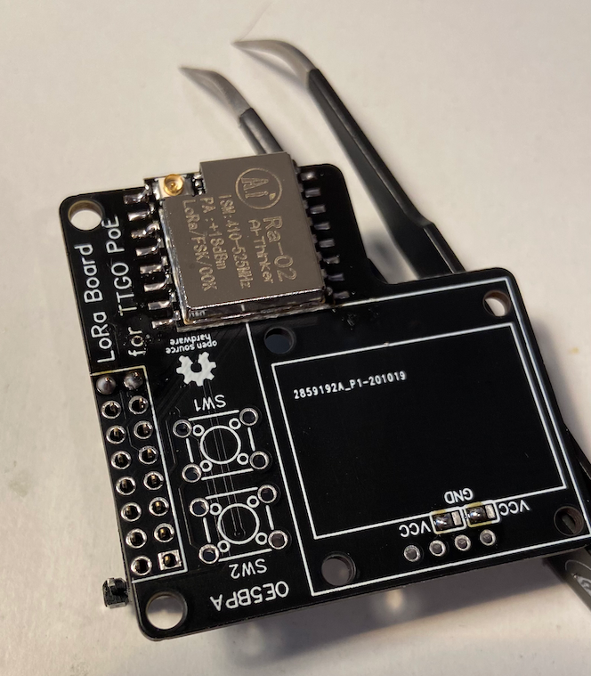
2Modem PCB: Solder the LoRa modem
Start with the modem, take care of the orientation and take your time.
![]()
Like you can see in the picture it is first not very nicely done. Remove the solder which is too much with a desoldering braid.
-
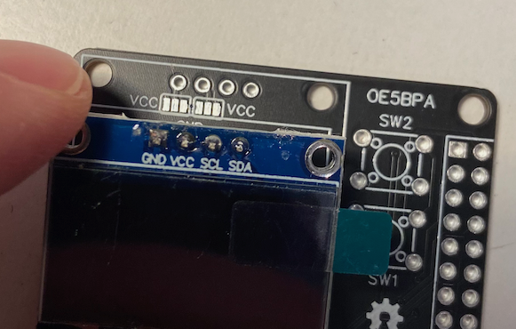
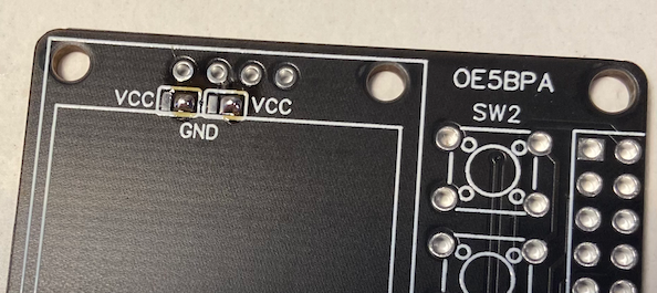
3Modem PCB: take care of the LCD supply
The board can take all two versions of the LCD (switched power pins). Just solder the correct pads together. Take the two pictures as an example. Don't solder the LCD now on the PCB.
![]()
![]()
-
4Modem PCB: pinheader
Solder the 2x8 pinheader on the downside of the PCB. I am using a tweezers to get the board straight for simpler solder joints.
![]()
-
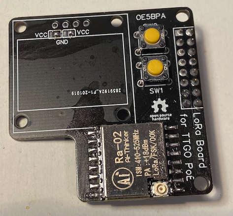
5Modem PCB: button
Add the two buttons on the PCB and solder them.
![]()
-
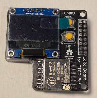
6Modem PCB: LCD
Now solder the LCD and you are finished with the modem board.
![]()
![]()
-
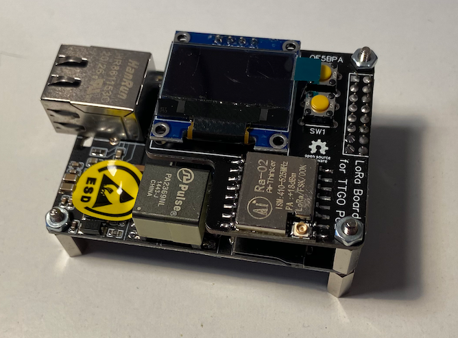
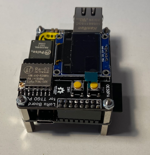
7Finish the build
Stack the two boards together with the spacers and the nuts.
![]()
![]()
Congratulations the complete build is finished now.
-
8Flash the ESP32
LoRa APRS iGate on ESP32 PoE Board
This LoRa APRS iGate is using the T-Internet-PoE Board from TTGO.
Discussions
Become a Hackaday.io Member
Create an account to leave a comment. Already have an account? Log In.