DIY Ringlight
The spotlights on my microscope didn't cut it. So I'm making a ring light to improve video quality.
The spotlights on my microscope didn't cut it. So I'm making a ring light to improve video quality.
To make the experience fit your profile, pick a username and tell us what interests you.
We found and based on your interests.


Finally done with the project, it has definitely improved video quality (as far as it can be with the microscope itself being the limiting factor), the image is still a bit noisy but the ring light has helped remove shadows that were cast by the spotlights, I will still use the spotlights alongside the ring light though.
Spotlight only:
Ring light only:
The PCB's arrived this morning and I have assembled both boards and tried fitting them in the housing, need to make some changes so I am working on another version. This was my first time using a stencil and solder paste. I definitely want to make a pickup tool and paste dispenser in the future, almost all the joints on the dimmer PCB had too much solder.
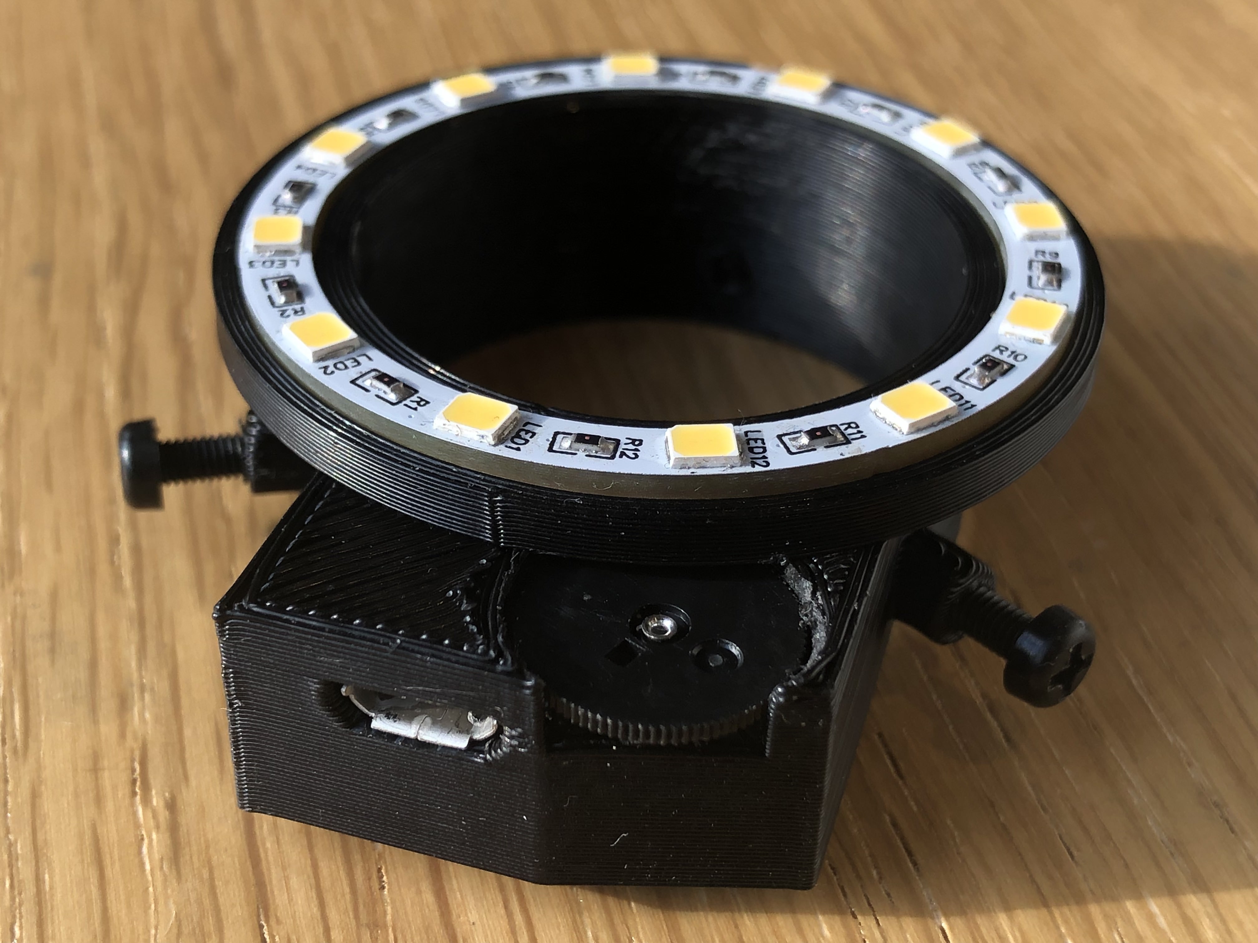
Assembly went fine, you can see more images on my Instagram: @lectro_net but here are some brief ones.
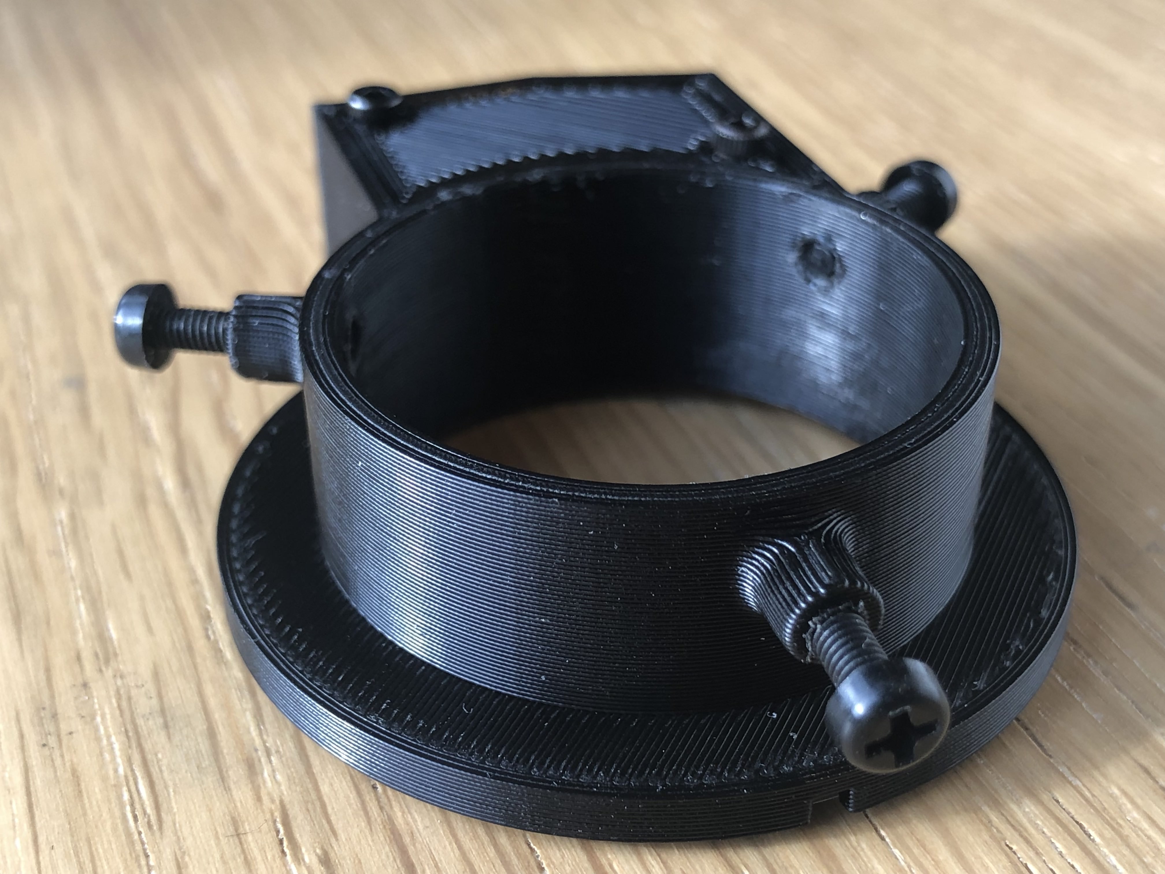
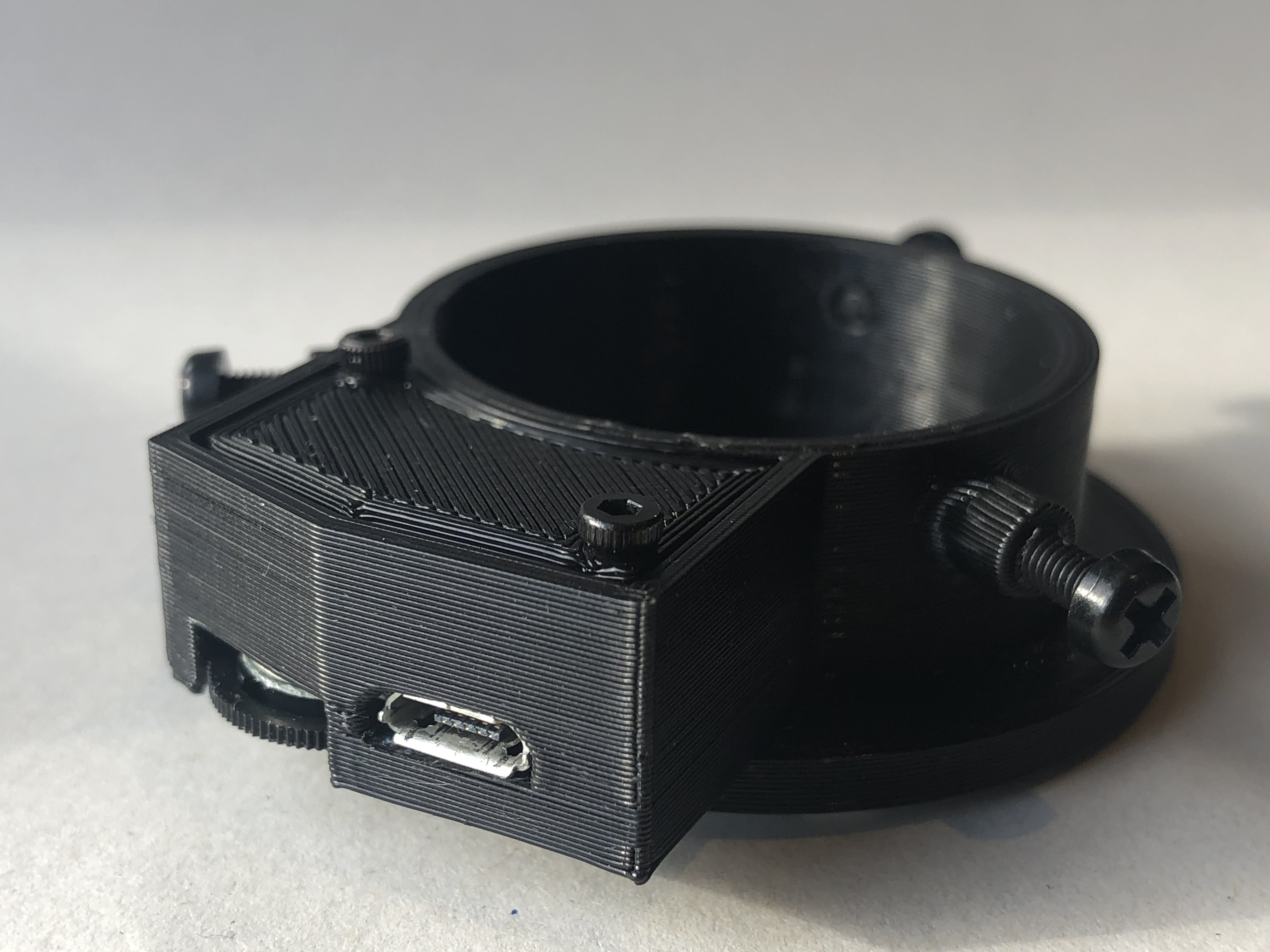
This is the body of the ring light, the brightness will be controlled with a potentiometer which you can see in the images below, I do worry that I may not be able to drop the PCB in but if that's the case then I can make some modifications, I didn't have space for screw holes in the LED ring so I will have to use a friction fit or rely on the translucent diffuser/lens to hold it in place. This is just the first version though so I don't expect it to work smoothly, ill definitely need to cut, file, and melt some areas.
When I get a PCB assembled I will look at the output, interested to see if the compact design increases the frequency and produces a cleaner wave.
I had a 555 timer-based PWM generator lying around for another project but I noticed it flickered on camera so I made some tweaks to the circuit and increased the frequency from 1kHz to about 30kHz, hopefully, there won't be any flicker, if there is then its just a simple change of a capacitor.
I don't expect the ring to get very hot but in case it does, I made the ring as dense as possible with copper and exposed the copper on the backside.
For the dimmer PCB, I just made the timer circuit as small as possible, I'll be using micro USB to power the ring light and the microscope and I shouldn't see any issues with current consumption from the USB power supply.
The ring is estimated to take 720mA at full brightness, ill be running each LED at 50mA instead of 60mA, which will keep it cooler as well.
White solder mask on the ring is to prevent any colour distortion.
The PCB's are on the way as well as the components. I also bought a stencil with the led ring, first time using one so will be interesting. I also bought an MHP30 by MiniWare but just realised that the heating plate is too small :), may need to do it in sections or something.
The next update will be when everything arrives and I can start to assemble, haven't tested anything except the 555 timer circuit so hopefully the LED ring is ok.
Create an account to leave a comment. Already have an account? Log In.
There are but it's more for single LED's on a PCB not a ring of them, for that you'd need custom optics. I may experiment with that but even without optics the light is pretty good actually, it makes more sense to get a better microscope now rather than tweaking with optics to make full use of all the extra light.
very nice looking! I made one with 10mm leds and one prior with SMDS. Yours way more appealing on the eyes. Love it.
Thanks for the comment, I was thinking of using THT LEDs so I can angle them but it would have been too big for this very small microscope. Maybe if I get a trinocular one I'll make a big version.
Become a member to follow this project and never miss any updates
I am wondering, is there an optic lenses suitable for SMD LEDs. To form a more straight light stream.