schuhumi
-
smoking robot out of control
08/08/2015 at 18:31 • 0 comments"Angstwiderstand" (literally "fear resistor") is a German expression for resistors you put in your design that do nothing in normal operation. Here's why you should put them in there anyways:
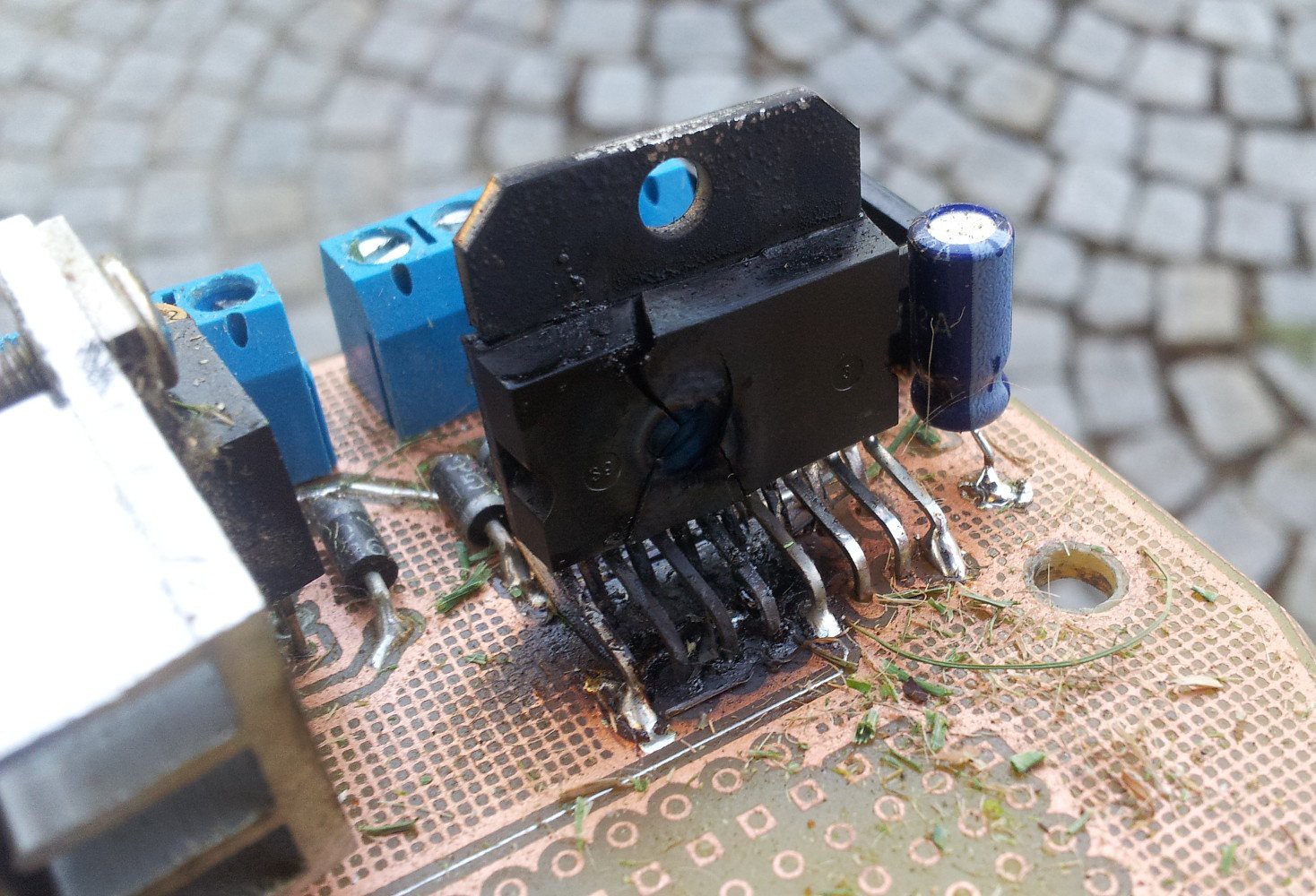
Today I had a few problems with the h-bridge controlling the height adjustment. Later I foolishly left the robot unsupervised in the garage with the high power circuitry on to let the usb power banks charge. After some time the l298 h-bridge went nuts:
![]()
![]()
![]()
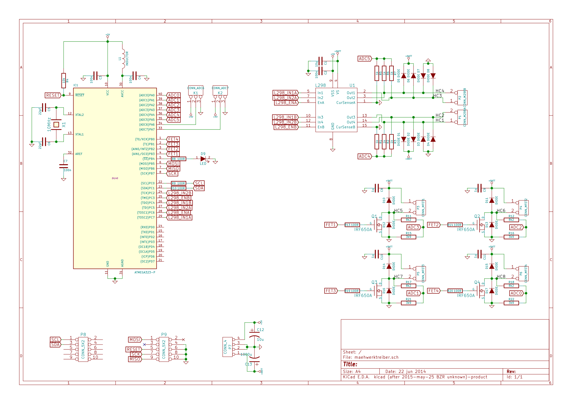
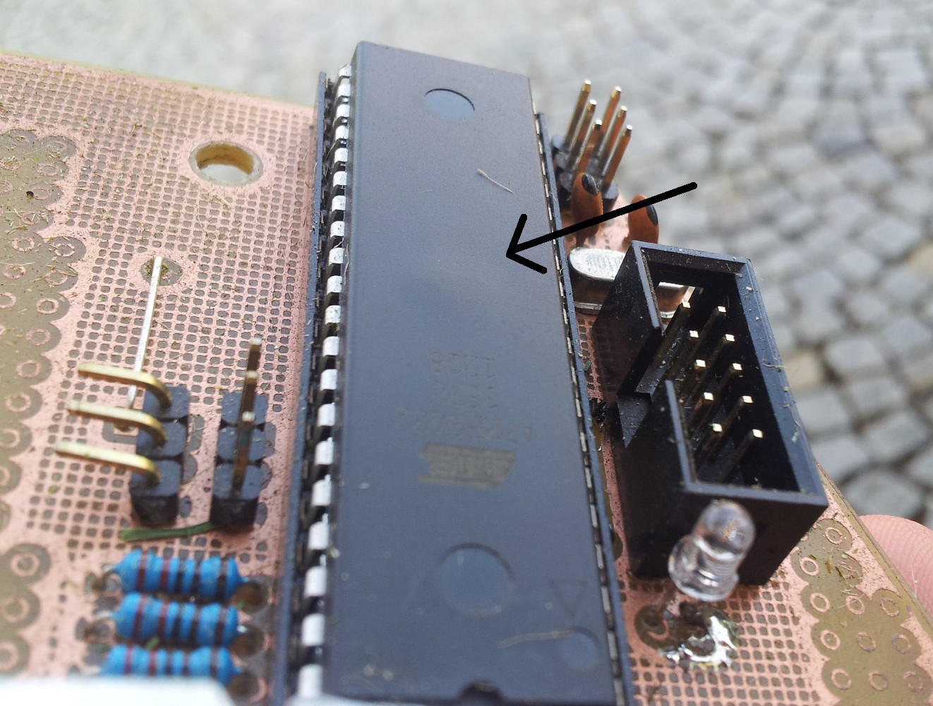
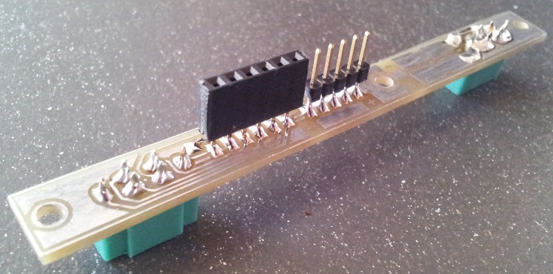
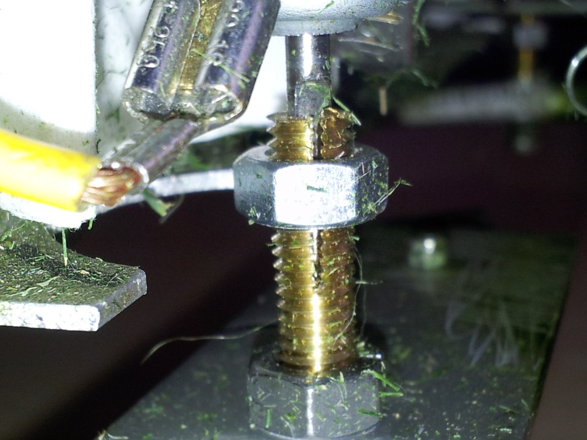
Now that's toast. On the high power side the l298 is connected to the 14.8V power rail (+BATT), the input pins are connected to the microcontroller:
![]()
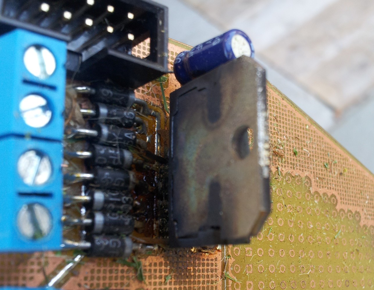
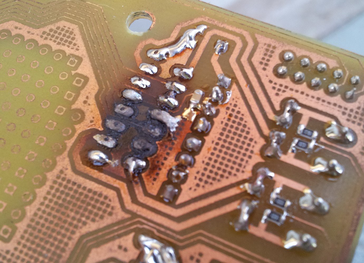
It seems like while bursting in smoke the l298 shorted +BATT to the micro, which destroyed it. Have a look at that bulge:
![]()
As you can see in the schematic the micro also controlls 4 FETs, two of which power the mowing motors.
As a result I had a smoking robot running it's mowing blades at full speed despite all controllers powered down
When I discovered that scene gaining control again luckily was as simple as flipping the switch for the high power circuit. Things learned from this:
- Put current limiting resistors in datalines (Angstwiderstand) to protect components from each other in case one blows up. In this case 1k resistors in all connections between l298 and microcontroller could have prevented this scenario
- Don't leave weird contraptions unattended with only a mosfet preventing them from becoming hazardous
-
Snow Shield & Refurbishing Drive System
12/30/2014 at 22:43 • 0 commentsWell, it has been some time since the last update.. - but with vacation now there's stuff happening:
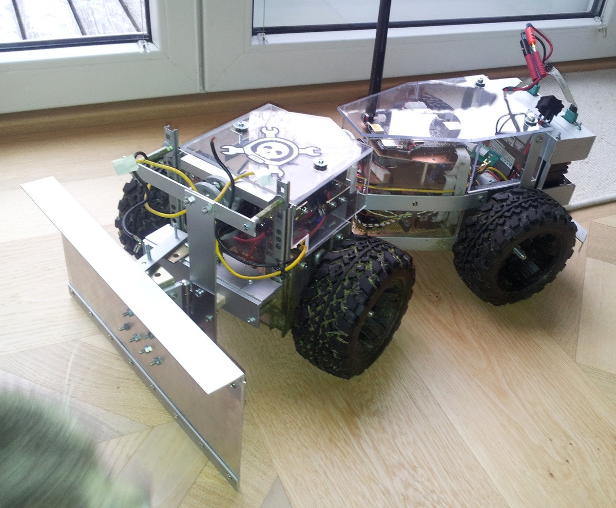
![]()
As you can see the casing on the back made some progress and there's a snow shield now!
I assure you it does work reasonably well, but I missed to shot a video and took it apart shortly after. The reason is that now the drive system has to do some heavy work and it revealed some issues:
- The mounting of the wheels to the motors is not sufficient for snow plowing
- The drive system supports two modes: a) regulate torque: measure a torque-ish value from the front wheels, do some calculus and apply it to the back whells b) regulate speed: the speed for all wheels is regulated individually, this isn't ideal for flat surfaces (more motors than there are degrees of freedom -> slightly tearing tires due to inaccuracies) but very nice for snow. Problem: b) doesn't seem to work as nice as it once did, not sure why though. I suspect the BackEMF-speed-measurement to have some trouble
Countermeasures:
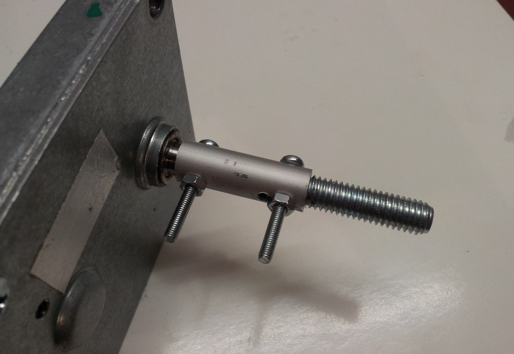
![]()
this is the new mounting system for the wheels. Yes, I drilled wrong :-D No problem though.. Thanks to the screws there is no slipping no more and the axis is quite straight as well.
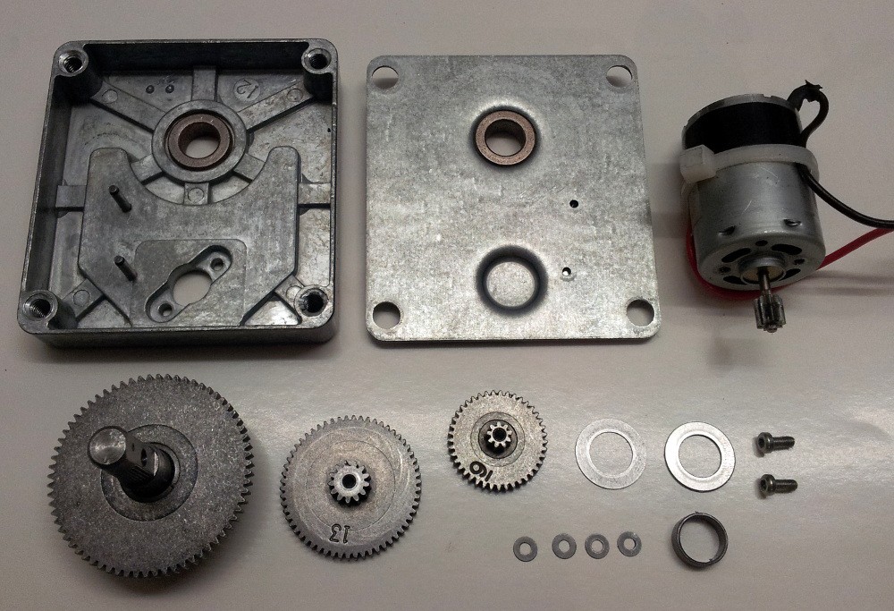
Another problem with the motors was that the connections between gearbox and motor itself were loose in all cases and therefore the whole assembly was rather noisy. To solve that I opened the boxes. Sadly they're not meant to be opened so you have to drill-open them (6-7mm drill, go down ~2mm in each corner). This is what you're greeted with:
![]()
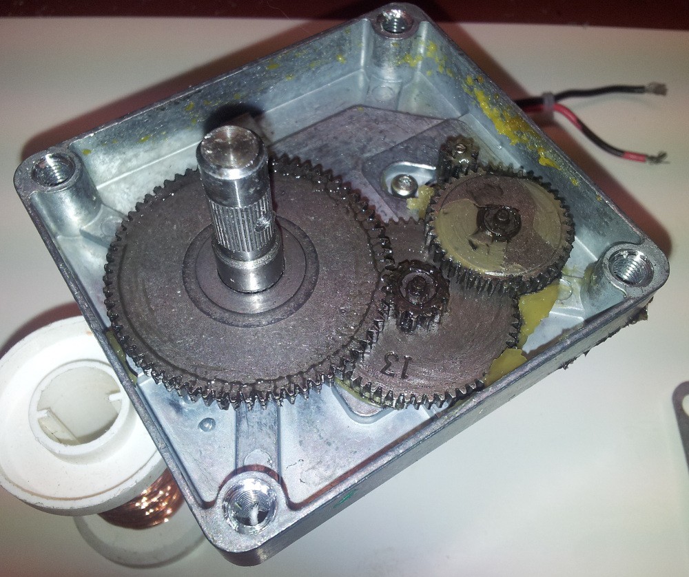
Cleaned of the nasty grease (<- honestly the most work) and disassembled:
![]()
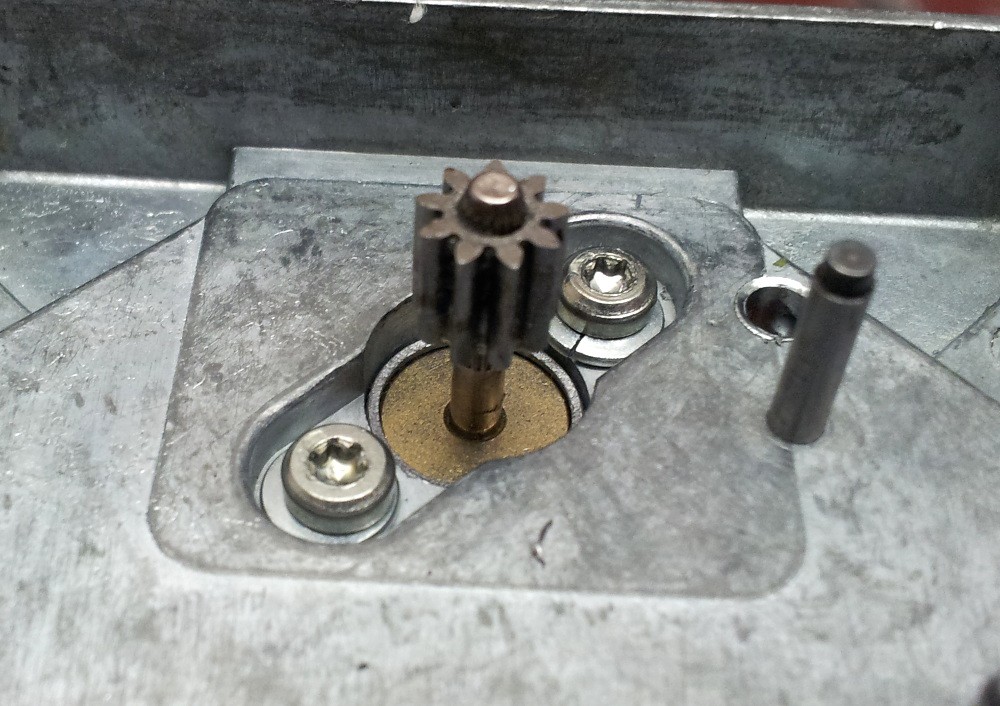
The motors are mounted with (slightly oversized) retainer rings, originally only loctite was used.
![]()
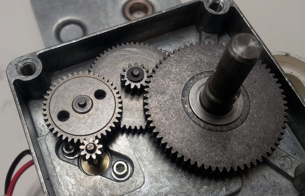
And here's the clue regarding the speed measurement:
![]()
BackEMF is going to be supported by photoelectric sensors, hence the two holes in the gear. Why not replace BackEMF completely? Well, these are the numbers of teeth of all the gears:
- Motor: 9
- Small gear: 9, 41
- Middle gear: 13, 58
- Big gear: 67
Therefore the number degrees per either rising or falling edge from the photoelectric sensor are:
0.5 * 9/58 * 13/67 * 360° = 5.4°
With the 14cm wheels that's a distance of :
0.5 * 9/58 * 13/67 * 2 * Pi * 70mm = 6.6mm
And I'm pretty certain that that's not enough for proper regulation on very low velocity. Now I could drill more holes into the gear, but those are so damn rock solid I ruined all my 3mm HSS-G drill bits with the 4*2 holes already - so no, won't do that..
For the sensors itself I ordered 3mm (like LEDs) phototransistors which get inserted in a 3mm hole on one side of the gear and a 3mm LED on the other.
In case you're interested the the motors: CHM-2435-1 is their model number and they're quite cheap. Got mine for 9€ each on http://www.pollin.de/shop/dt/Nzc1OTg2OTk-/Motoren/DC_Getriebemotoren/Gleichstrom_Getriebemotor_CHM_2435_1.html
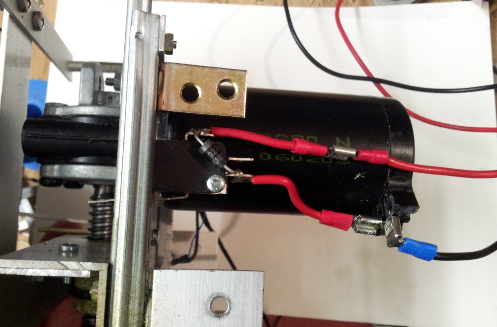
And here's another minor thing I added to height adjustment mechanism:
![]()
Before in case the connector of the height measurement would have become loose in theory the motor could have teared the assembly apart or made the circuit burst in smoke. Now it gets shut off by a limit switch and a diode allows it to drive down only
-
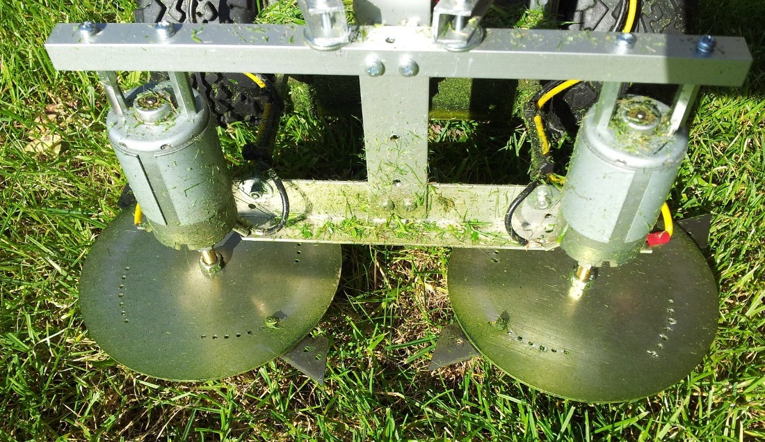
Testing the new mowing system
10/10/2014 at 21:09 • 0 commentsThe last few days I was busy with rebuilding the mowing system. Now there's a lot less noise and vibration. It also got the laser cut hood mounted with springs to make it flexible.
![]()
The gain in power is just astonishing:
-
New embedded Linux computer
10/08/2014 at 21:22 • 2 commentsNo doubt that the Raspberry Pi was the Board bringing embedded Linux to hobbyists and tinkerers. In fact I was one of the very early birds purchasing one. As you might remember RS and Farnell got DDOS'ed very badly - it was an awesome feeling seeing the Rapberry gathering that much attention.
But at the moment I'm a bit fed up with it:
- Slow CPU
- Very limited RAM (remember that the first version had 256mb only)
- Power consumption is not particularly low
- Most annoying: A terrible hardware related I²C bug which makes communication with AVRs very hard. If an AVR can't handle an I²C event immediately it uses clock stretching, but this can screw up the Raspberry's I²C-bus hardware wise.
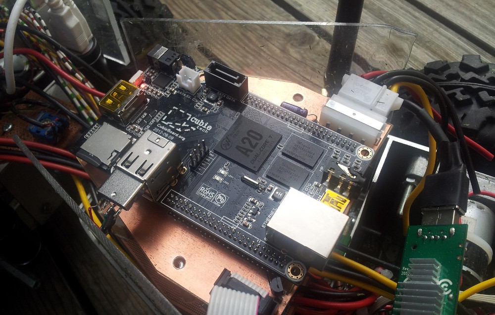
I checked all the boards supported by ArchLinux ARM and settled with cubieboard 2:
![]()
It sits on a home etched PCB and is only connected with 5V/GND/I²C
Some benefits relevant for this project:
- Proper I²C interface (!)
- Dualcore A20 Processor is very fast
- 1GB of ram
- Less power consumption
- 4GB internal flash. The cubieboard 2 (Class 4 µSD) already boots faster than the Raspberry Pi (Class 10 SDHC), and usage of the internal flash would reduce boot time even further.
- On shutdown the board actually switches itself off - this could be used as a power off signal for the power supply module
- Extension headers on the right side of the board (bottom)
Things that are not ideal (just minor flaws):
- The extension headers are 2mm, so prototyping boards are not an option
- No USB on extension headers
- To power it through the header one diode (D2) needs to be shorted ( http://www.iotllc.com/joomla/index.php/forum/baseboard/2-powering-the-cubie-with-the-baseboard )
So far I'm very happy with it!
-
Ultrasonic distance measurement master <-> node
09/27/2014 at 18:06 • 5 commentsMeanwhile I got a working master and node. The master can send a package (one byte so far) to the node, the node responds and the master calculates the distance:
Keeping in mind that it is calibrated rather loosely the results are very good. The distance value is very stable and +-0.5cm accuracy should be archieveable.
What the data package looks like:
- two start bits (both high)
- four bits target address
- four bits command (The master transmits 1=DoEcho and the node responds 2=EchoReply)
- two parity bits
- one stop bit
I need to increase the number of parity bits, because two bits result in an easy 25% chance for the parity to be right anyways.
-
laser cut aluminium parts arrived
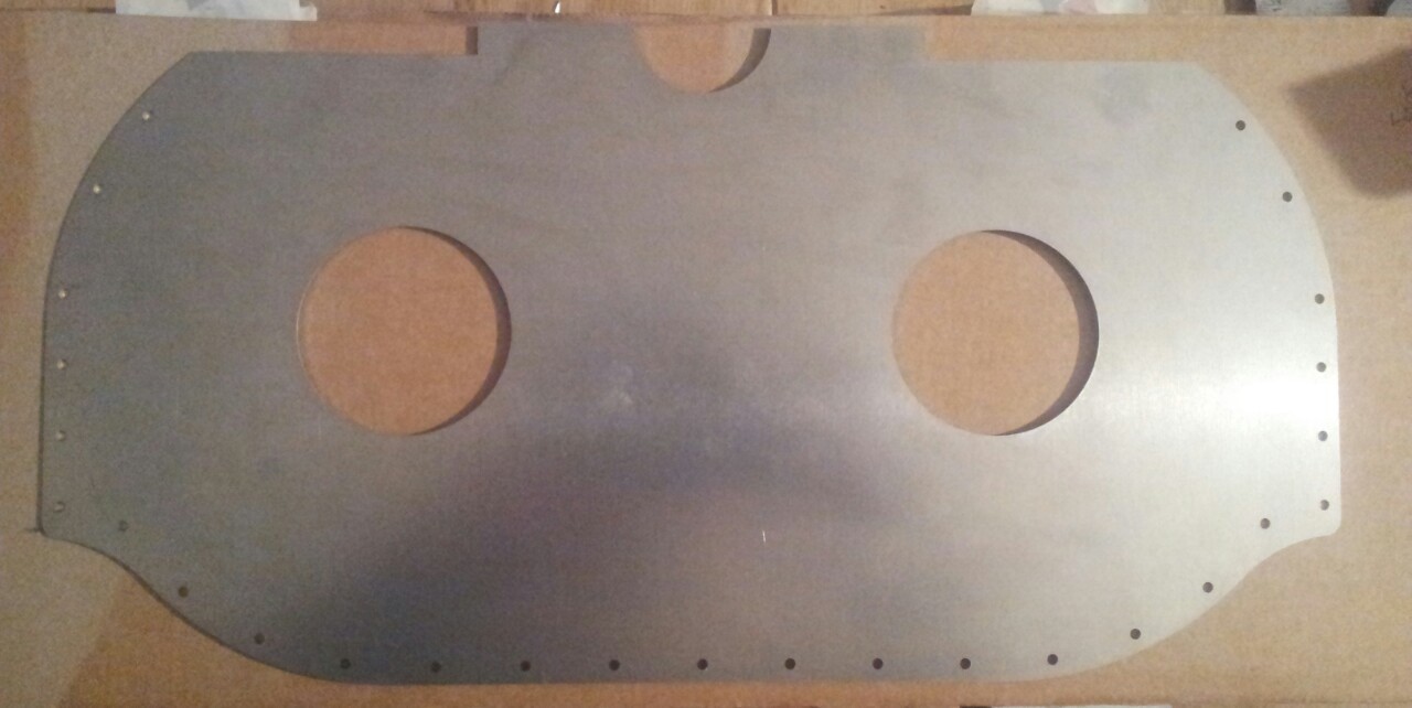
09/24/2014 at 22:31 • 4 commentsCutworks where surprisingly fast (compared to the estimated delivery date in their mail (10. oct)). Everything turned out very nicely. The hood (sorry for bad quality, phone had problems with focus):
![]()
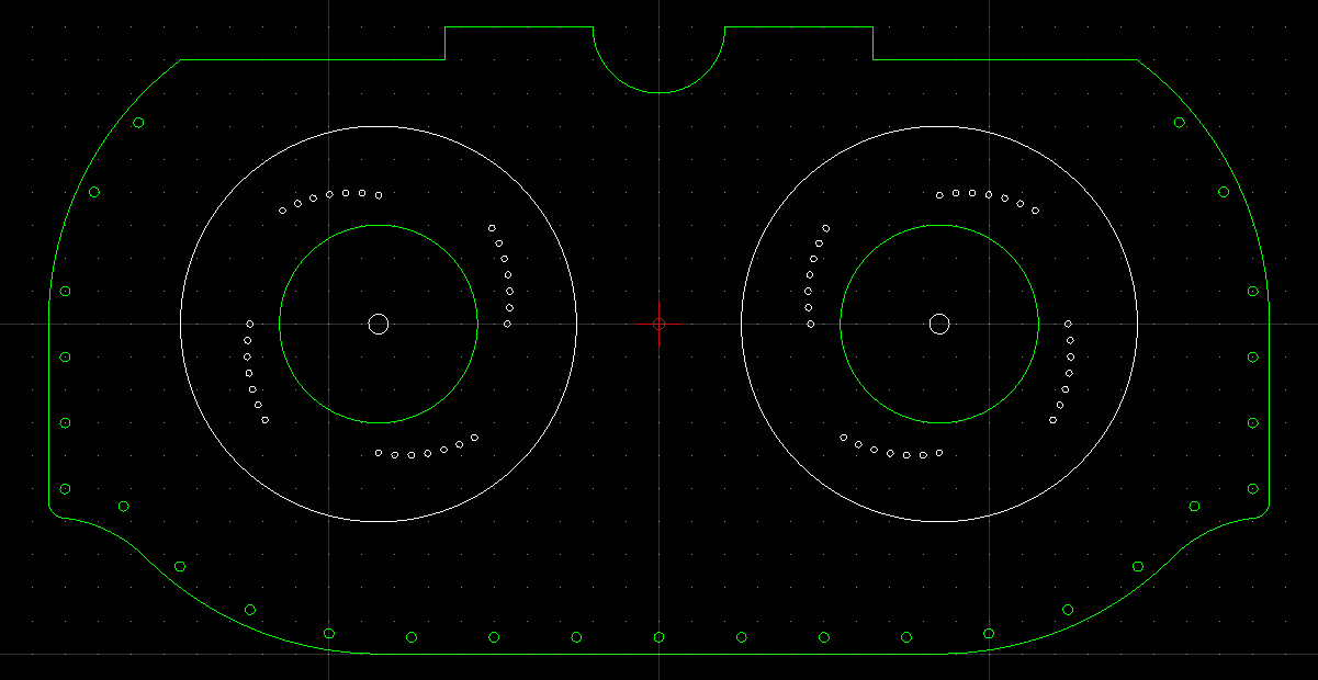
The the platters:
![]()
As you can see either two or four blades per platter and variable diameter are possible. Mowing some grass:
The new platters reduced the noise a lot, but there's still some vibration due to worn out bearings (previous designs rather unbalanced) and inaccurately modified motor shafts (previous designs needed a flattened shaft).
-
Ultrasonic data transmission - proof of concept
09/16/2014 at 22:03 • 2 commentsOne of the outstanding features of autoCut is the ultrasonic positioning system. Since no other (lawn mower) robot I heard of has this feature it's a tough one. I posted a sketch on how this could work and I set out to make a proof of concept.
After some tinkering it works very well, here's a demo:
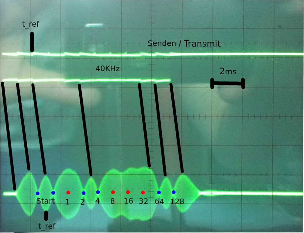
This is how it works:
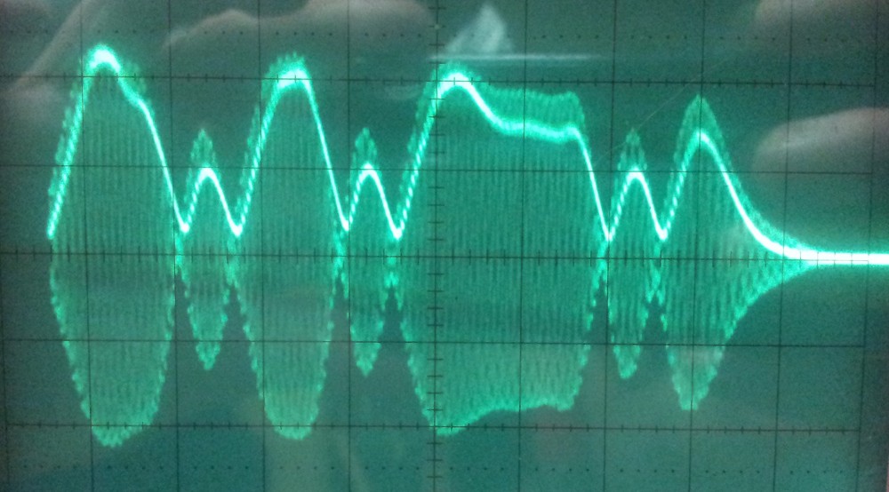
![]()
The signal on top is the one fed into the ultrasonic transmitter. It is 40KHz as long as data is transmitted, and on every 1 there is a phaseshift of half a period (waves get inverted). On the oscillating receiver this causes the amplitude to drop to 0 and then start rising again. So 1es are where the amplitude is zero (blue dots) and 0 are where the amplitude remains high (red dots).
In this case the data stream is 01100011, written in correct binary: 0b11000110 (least significant bit gets transferred first).
![]()
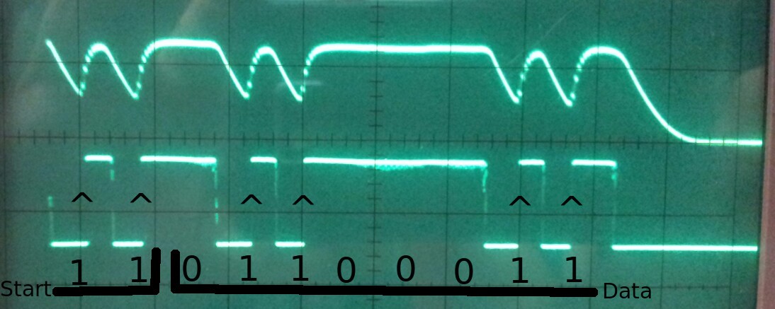
The signal of the receiver gets amplified, one-way rectified and buffered by a capacitor. This creates a signal the represents the amplitude of the received signal.
![]()
With the help of a small phaseshift (caused by resistor+capacitor) comparator creates a digital signal which indicates when a signal starts rising or falling. Now when the amplitude is ~0 and starts rising again, the digital signal switches from low to high. Under friendly conditions this is enough already to decode the data stream.
![]()
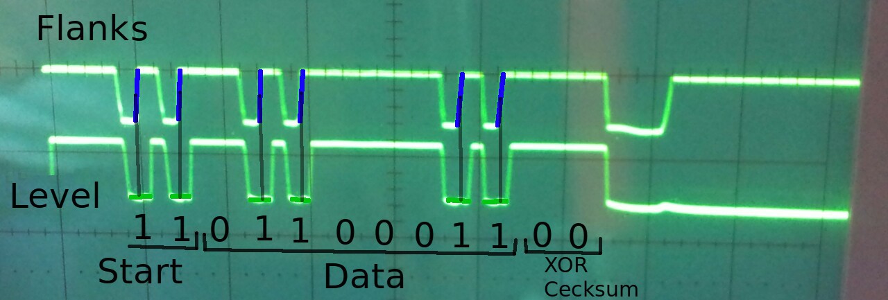
To make sure that the switches from low to high are valid 1es (amplitude must be near zero) another comparator is used to create a signal representing the level of the amplitude. To receive a valid 1 the flank from low to high must occur AND the level of the amplitude must be zero. As you can see I also introduced a small XOR-checksum, which will be extended to 4 bit due to occasional false data (2 bit: 25% chance that checksum of corrupted data stream happens to be right).
So far I'm pretty satisfied with the results. Improvements I'm working on:
- use MAX232 as amplifier for the transmitter
- use better receiver/transmitter capsules
- use a better operation amplifier for the received signal (CA3140 so far which can't do rail-to-rail -> 2-3V max output on 5V power supply)
- Get bidirectional data transmission and distance measurement working
- work out a way to spread the sound into all directions
-
Bunch of minor updates
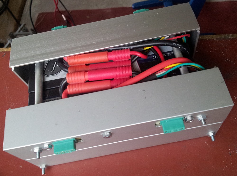
09/16/2014 at 20:30 • 0 commentsAlready some time ago I built this prototype of a battery pack:
![]()
It can hold two 14.8V 5Ah LiPo batteries wired in parallel. I did some tests with one battery earlier and estimated from that this should be enough to mow at least 1.5h non stop.
Apart from connector orientation the design is mirrored. The front face with the two connectors will sit on the robot with the left connector providing the amps and the right one reporting individual cell voltages. The connectors on the other side (facing upwards when battery pack is mounted on robot) do exactly the same. The idea is that the battery changing station can grab the pack and connect to it in one step. The changing station will be a big disk that can rotate, move up/downwards and hold up to 3 battery packs (see sketch on system design)
The biggest problem on a mechanical point of view is how to craft the docking mechanism. The problem is that this has to be very accurate to work smoothly, but my most advanced tool is a cordless drill... Fine adjustment must be possible via screws with washers in bigger holes or something.
This are the electronics inside the battery pack. There are two of these simple boards in one battery pack:
![]()
As you can see rather simple, simply a bunch of connectors and solder pads to join everything in parallel and provide mounting options. The PCB is homemade via toner transfer (probably should do a video on my selfmade laminator and etching machine..)
I also purchased the mowing plates and hood that will be laser cut from aluminium:
![]()
As you can see blades of different sizes and two or four blades per plate can be mounted.
All in all it's 65€ and the parts will arrive ~ 10. Oct. I purchased at http://cutworks.de/ an their website/tools are really great, will see how the parts turn out.
-
Thoughts on the ultrasonic navigation system
08/23/2014 at 00:34 • 3 commentsAs you might have read I claim the ultimate goal of the robot to be to navigate through the garden with an ultrasonic positioning system. I thought about navigation and positioning since the beginning of the build, but just recently something came up my mind that I think of as an realistic solution: sound
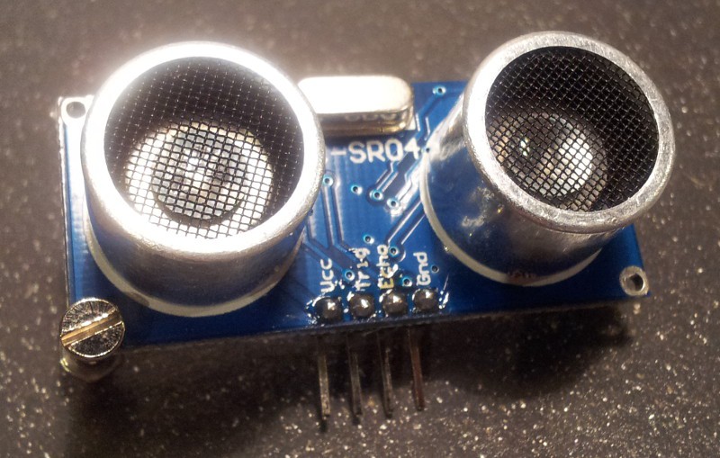
Sound moves rather slow compared to the speed a microcontroller can process data, thus making precise distance measurement easy. There's a great chance you actually used one of these at some point:
![]()
This is a HC-SR04, a cheap (~5€) ultrasonic distance sensor widely used by hobbyists. The principle is fairly simple: One of the round thingies is an ultrasonic speaker, that transmits a short ultrasonic burst into the world. Eventually this sound reaches an object and gets reflected on its surface (echo). The other round thingy listens for that echo. The delay between transmit and the receive is what the module sends to your microcontroller which can then easily calculate the distance from that.
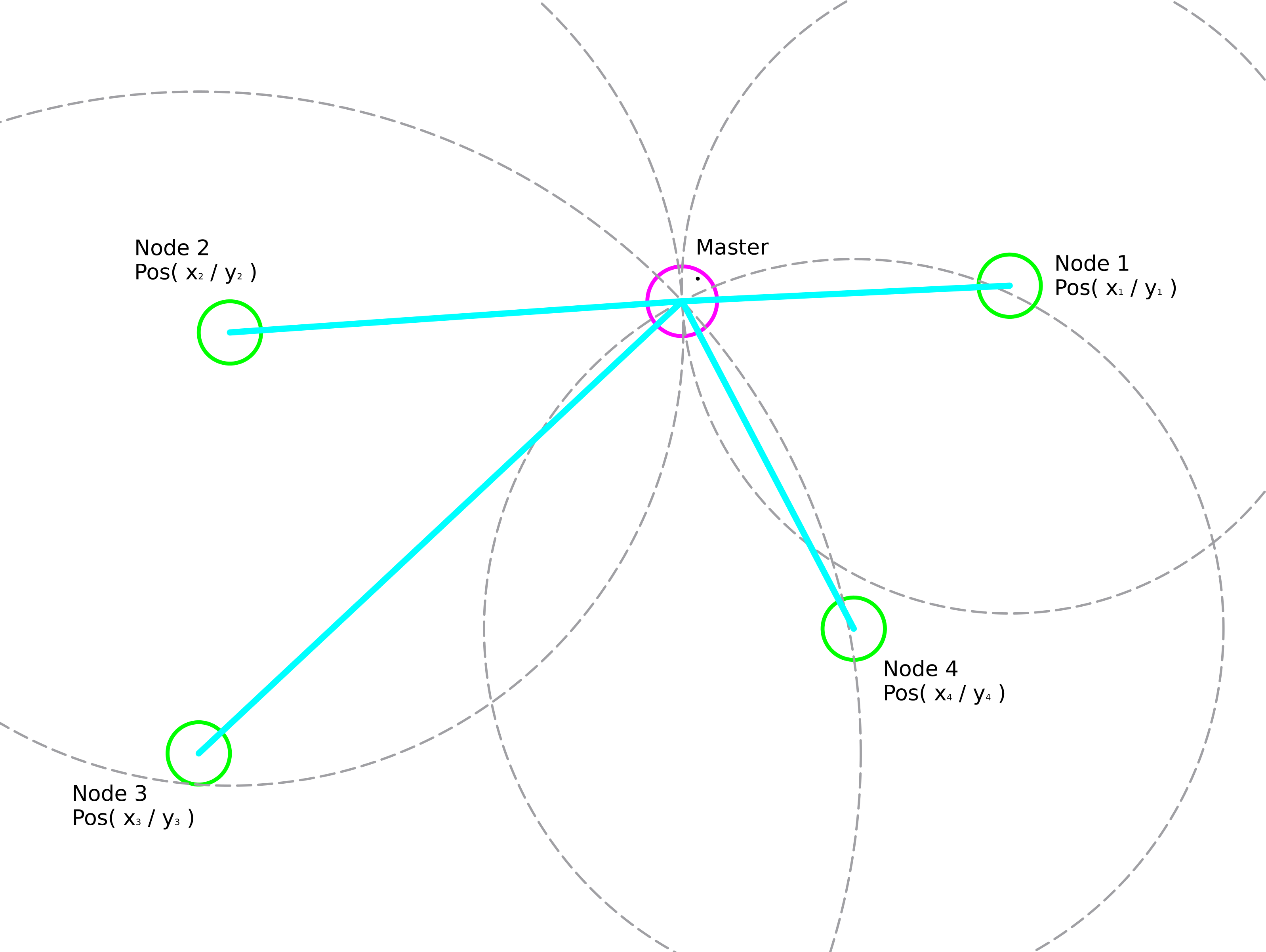
Now I want do take this principle one step further:
![]()
The master is the robot and has an ultrasonic transmitter as well as an ultrasonic receiver. The nodes are small circuits with microcontrollers and equipped with transmitters and receivers as well. For the master to calculate its position it needs to:
- Know the nodes
- Know the distance to each node
- Know the nodes position
Know the nodes
That's an easy one: just tell the robot the nodes ID via the web interface
Know the distance to each node
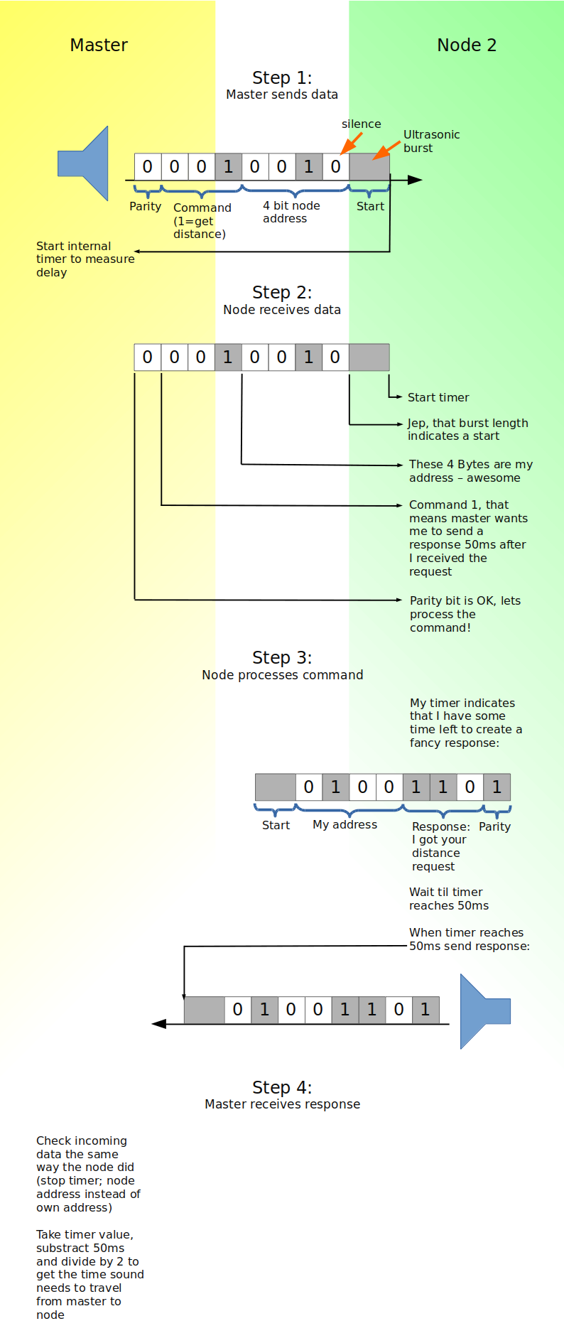
Here the ultrasonic sound comes in: The master sends a few bits encoded as ultrasonic bursts, including the nodes ID it wants to know the distance to. The nodes react accordingly, here's a diagram on that:
![]()
Of course this is just some concept to present the basic idea. In reality it might come in handy to add unique message IDs to cancel out echos etc.
Know the nodes position
In theory the network could calibrate the node positions itself by measuring the distances between the nodes (master sends command like: "node 2: measure your distance to node 4 and report it to me!"). After measuring various distances it should be possible to populate relative coordinates for each node. Even if this doesn't work well in reality, I'd be happy with putting in the positions by hand (into the web interface).
Remember that this is just a concept that rumours in my head. Also making the robot itself work properly and building a battery changing station are to be done first.
-
Improving the mowing system
08/20/2014 at 18:56 • 0 commentsThe mowing system turns out to be one of the toughest parts to work out. Of course the robot can't mow as fast as it's gasoline powered competitor, therefore it needs to be very silent to compensate the longer noise-frames and not annoy the neighbours.
I decided to ditch the bearings since exactly aligning the motors with the bearings while maintaining a connection withstanding the tremendous torque was beyond my capabilities. (note that my most advanced tool is a cordless electric screwdriver / drill ). This shouldn't be too much of a problem, since one motor of this kind costs ~2.5€ and these probably need to be replaced anyways at some time since they have brushes.
This is how the shaft of the motors is connected at the moment:
![]()
(I can't see the bend when looking at the real thing - not sure whether camera or eyes broken..) To minimize vibrations I'll craft these once again as precise as I can and mount laser cut mowing platters to them:
![]()
The hood (green) will also be lasercut from aluminium. The straight sides are for mounting vertical flaps. They will not only prevent grass (and slugs..) from flying around, but also sense if the blades are about to touch the ground. Our garden (and probably most others too) has lots of little holes in it. That's not a problem with the rear wheels (front tips up a bit), but with the front wheels it occasionally happens that the blades get stuck. The design isn't finished yet, but the company that run this service are on operational vacation anyways.
JohnsonFarms.us wrote a comment whether I considered to use a string trimmer instead of blades. I built one and tried it out
![]()
Here's a video on that:
( Sorry for occasional brain overflow - either forgot how to English or to move the cam accordingly. The string trimmer is almost invisible since tiny grey surfaces move damn fast )
In a longer test I did previously the string trimmer (had strings on both motors) turned out to use just too much energy. The RPMs need to be very high to actually cut the grass and not just bend it, which makes it noisier than the blades. The idea is great, but I'll stick to blades.