I tend to make mistakes on my first pass of something - case in point, the PCB I designed had the resistors for the real time clock DS1307 chip acting as pull down resistors, and they should have been pull up resistors. (In plain English I should have connected them to the 5v line instead of ground). It's easily enough fixed and I have the clock working on the board, even if I have a bit of an ugly corner of the board...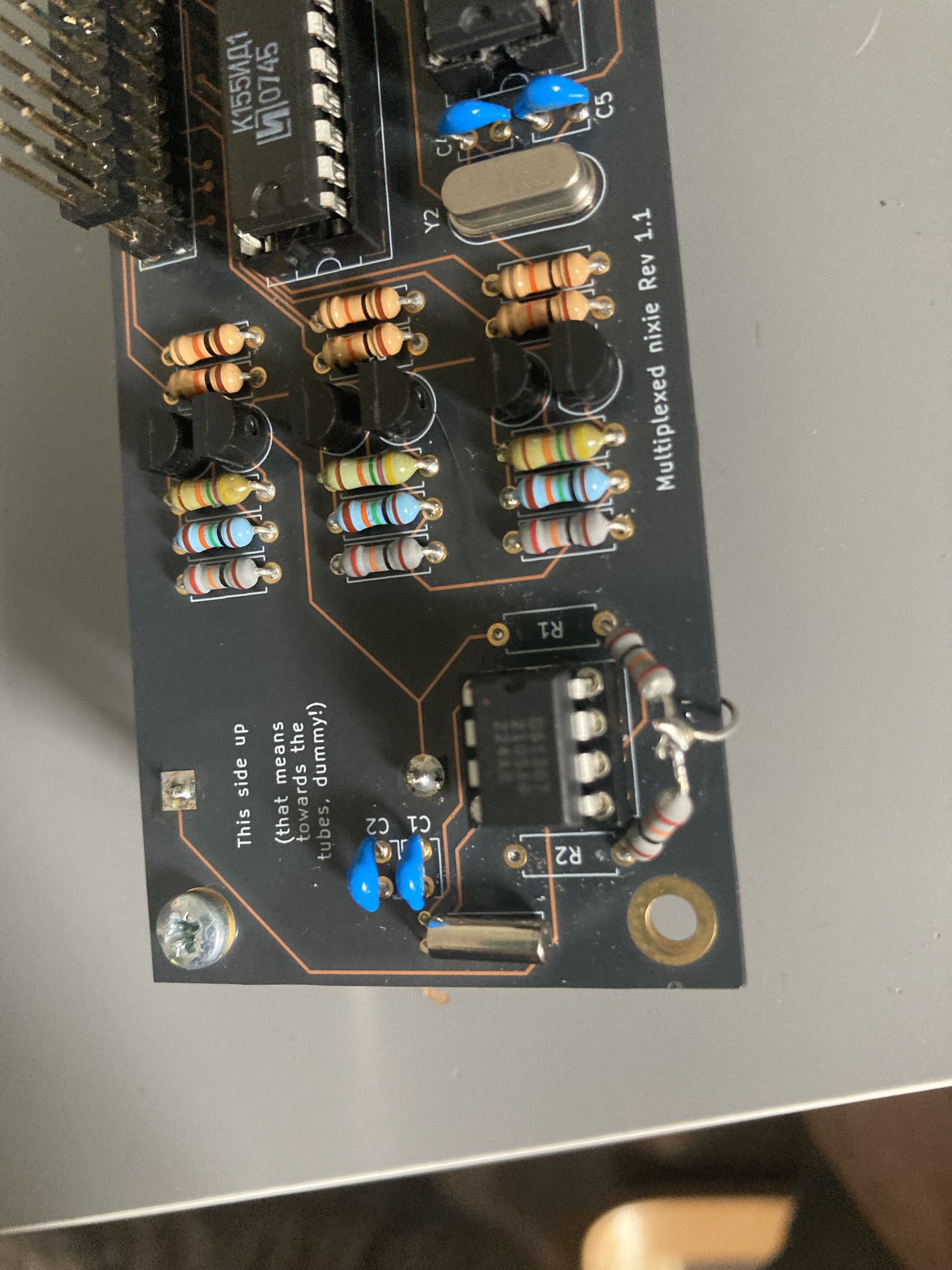
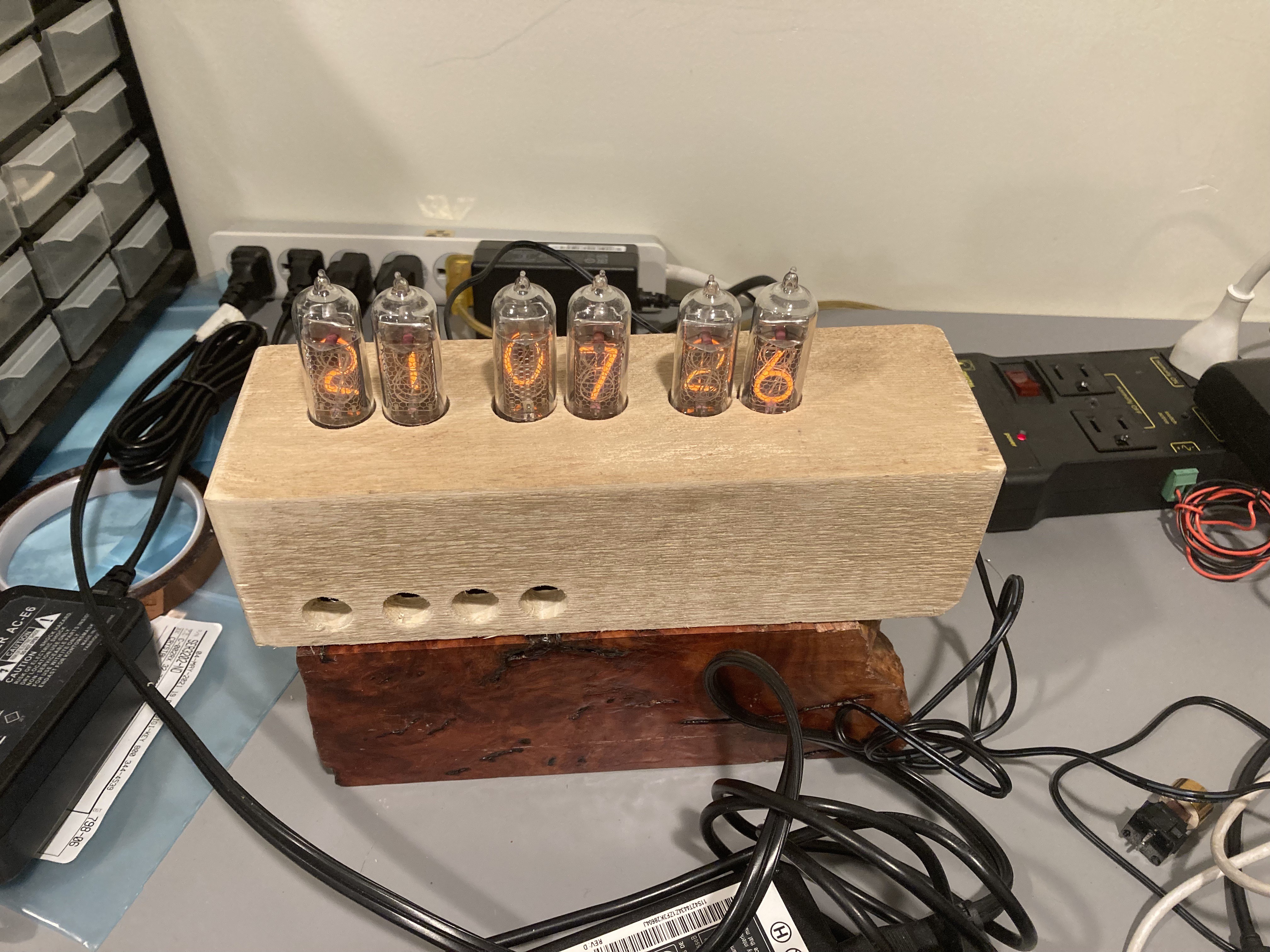
And I have the clock assembled and working:
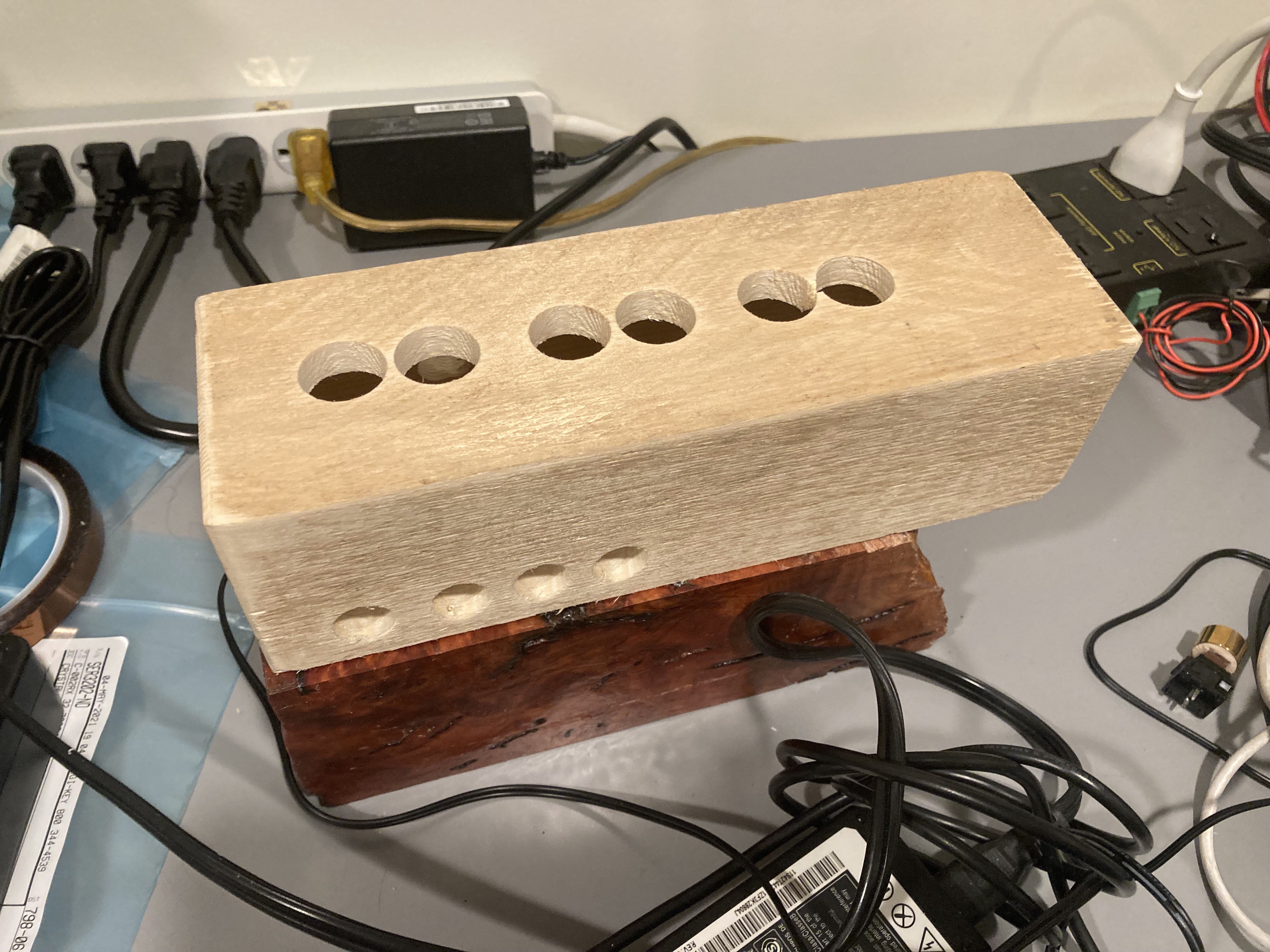
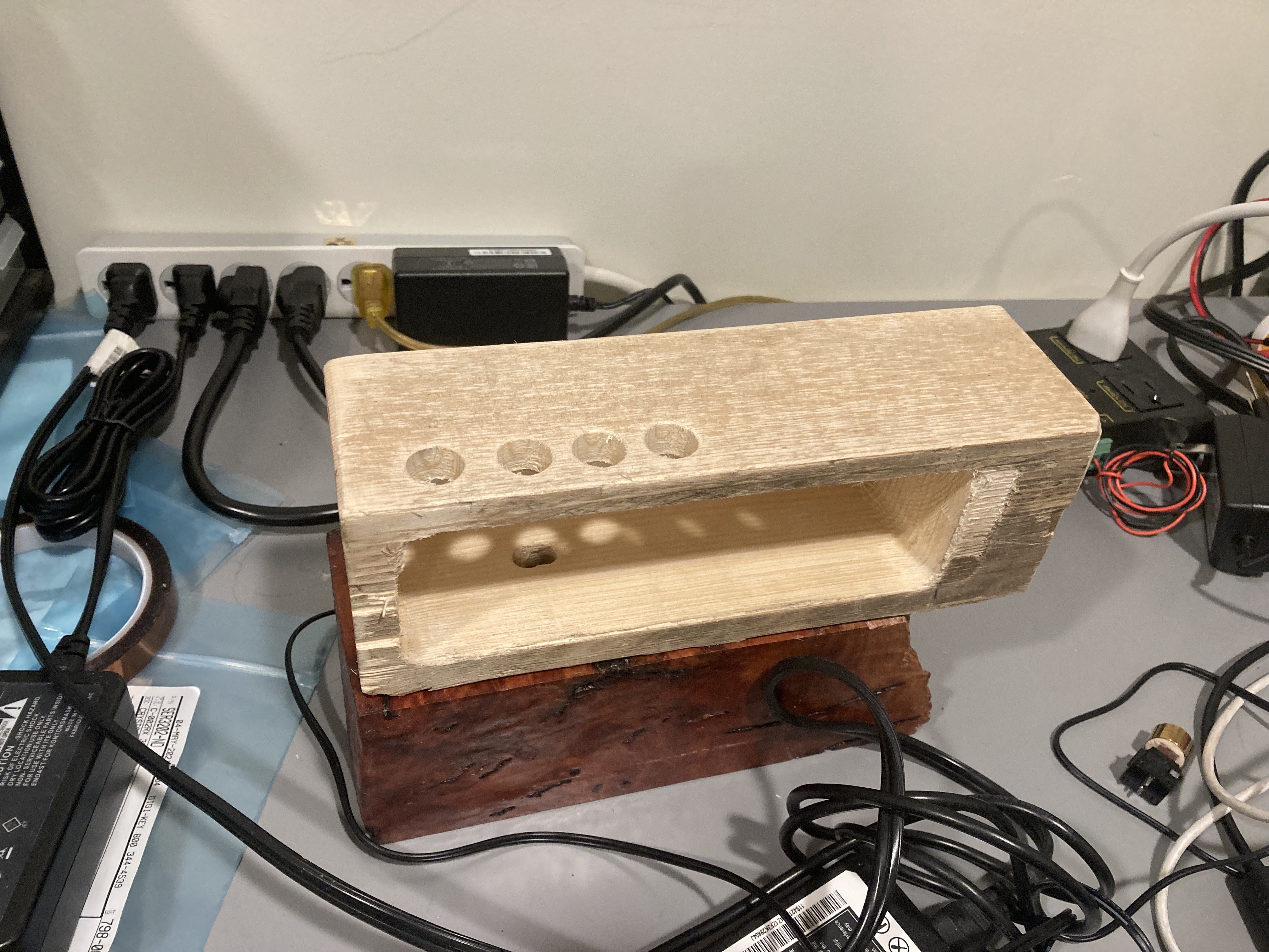
Finally, I milled out the test block (seen sitting on top of what will be the clock body for real) to ensure that my CAD design for the body worked:
Overall I'm pretty happy with the design - I need to figure out I want to mount it inside though as my original idea of having mounting brackets won't work. I tried neodymium magnets but those interfered with the inductor on the power supply. Smaller ones seem to work ok though, so I may go with that. Still much to think about.
There are definitely tweaks to be made before I cut up the expensive piece of wood though. I'm glad I did the test piece first!
Discussions
Become a Hackaday.io Member
Create an account to leave a comment. Already have an account? Log In.