Close
0%
0%

Ahmsville Dial V2

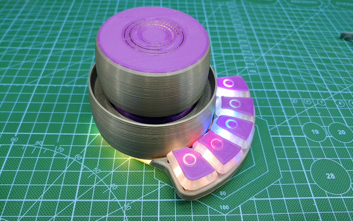
A 3D-printed programmable wireless/wired controller for your PC, and other electronics devices.

Similar projects worth following

I designed the first version of the Ahmsville Dial a little more than a year back, and I’ve loved using it, despite its limitations.

Last year I finally decided to update the dial, so I took all my experience with it, and put it into the development of the version two, with very specific goals in mind, my first goal was to create multiple version of the dial to cater to different types of users, my second goal was to make the dial operate in both wired and wirelessly modes, my third goal was to make the dial extremely easy to use even for people with zero programing skills, this largely meant I had to develop a companion app for the dial, the last goal I had was to give the dial context awareness, which simply means having the dial automatically switch its configuration to match whatever software your using it with, this way, the dial can be programmed to do different things within different applications...this feature is one of many enabled by the companion app.

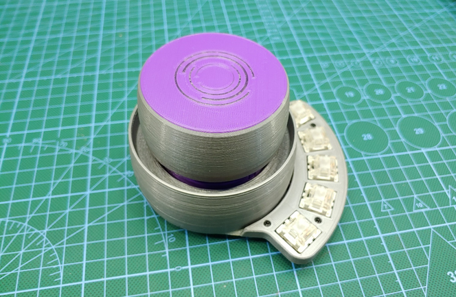
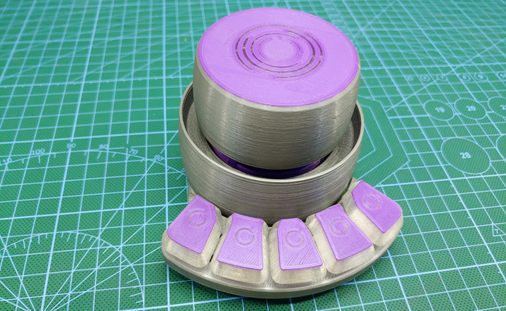
Ahmsville Dial V2 follows the same design philosophy as the version one, only with a higher resolution encoder, new hardware features, improved and streamlined code, simplified assembly process and the aforementioned companion app for windows users.

20210122_135703.jpg

                                                                       Ahmsville Dial V2 Variants

Ahmsville Dial V2 Project Video

The first big change to the system is in the circuit, the dial now uses the ATSAMD21G chip, which is the same chip used in the Arduino zero boards, and a lot of the MKR series boards, compared with the ATMEGA32u4 used in the previous version, this chip is much faster and generally better suited to handle all the new features of the Dial.

Main Sequence_3_Trim_gif.gif

                                                    Ahmsville Dial V2 Boards from jlcpcb.com

Another change to the system is the inclusion of a NRF24 wireless chip, with this, the dial is now able to operate wirelessly. I went this route because Bluetooth hid just wasn’t going to cut it, especially for the more advanced features I implemented in this version of the dial, the dial can also be used wired via the now included USB type C port, I have also made sure that there are no tradeoffs functionally between the wired and wireless modes.so switching between them is as simple as unplugging the USB cable from the PC and plugging in the wireless adapter or vice versa, the software on the dial is smart enough to handle the switching between all the connections.

The dial, although primarily designed for your PC, can also be used to control other devices, the wireless adapter which feature an ATMEGA32u4 has some of its pins broken out to allow for easy integration into other electronics systems.

Ahmsville Dial v2_Momeddnt.jpg

                                                             Wireless Communication Via NRF24

Dial Hardware Features

The Knob (Magnetic Rotary Encoder)

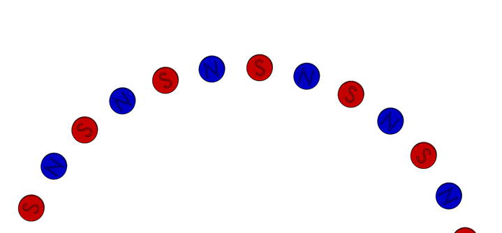
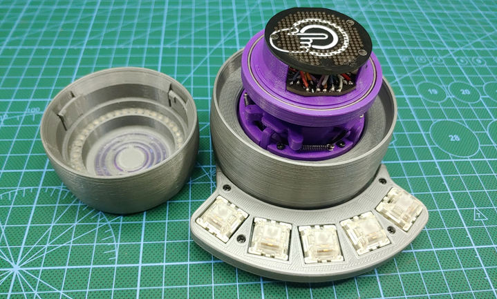
The rotary encoding method that’s used in the dial is one of my very own designs, it’s a ball bearing assisted, high resolution and contactless magnetic rotary encoder, the knob is fitted with a ring of tiny neodymium magnets in an alternating magnetic pole configuration; on the main board there are two linear hall effect sensors used to read the analog values on the magnets. This system allows the knob to operate through a ball bearing without ever touching the electronics, this makes for a very smooth feeling knob and is also one of the reasons the dial is so durable. This trend of isolating all moving parts from the electronics...

Read more »

Base Variant 3D files.zip

Zip Archive - 12.99 MB - 08/22/2021 at 22:55

Download

Macro key Variant 3D files.zip

Zip Archive - 21.29 MB - 08/22/2021 at 22:54

Download

SpaceNav Variant 3D files.zip

Zip Archive - 15.56 MB - 08/22/2021 at 22:51

Download

Absolute Variant 3D files.zip

Zip Archive - 24.42 MB - 08/22/2021 at 22:49

Download

View all 19 components

  • 1
    Gathering The Required Parts
    AHMSVILLE DIAL ABSOLUTEfinal_gif.gif

    To build the dial, you’ll need to get the kit with all the required custom PCBs from my Tindie Store,you can get the boards alone and source the rest of the parts yourself, I also have the full assembly kit with all the required parts available and you can also get the dial as a fully assembled device.
    3D printing files can be downloaded here.

    The assembly process is pretty straight forward and quit satisfying, I have also prepared detailed step by step Build Instructions for all the variations of the dial.

    Required Electronics and Hardware Parts 

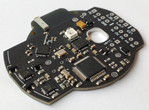
    Ahmsville Dial v2 Main Board

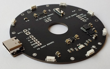
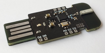
    USB C Board

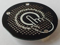
    Capacitive Touchpad

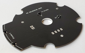
    Secondary Encoder Board


    Macro Key Board

    Wireless Adapter Board


    Vibration Motor


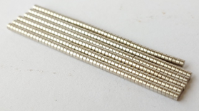
    2x1mm Neodymium Magnets (90pcs)


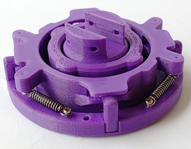
    Space Navigator Mechanism


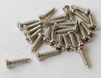
    M1.4x6mm Self Tapping Screws (2pcs)


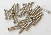
    M1.4x10mm Self Tapping Screws (19pcs)


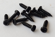
    M2x10mm Self Tapping Screws (4pcs) & M2x8mm Self Tapping Screws (4pcs)


    6809 Ball Bearing & 6811 Ball Bearing


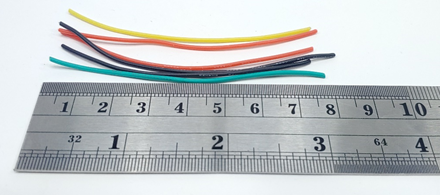
    Thin Flexible Individually Colored Wires (14 colors, length – 150mm) (For Primary connections to the Main Board)

    If you cannot get 14 individually colored wires, you can use a black permanent marker to create more colors, for example a plain blue wire marked with a black line becomes a blue-black wire.


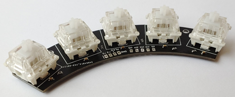
    Thin Flexible Wires (6pcs of length => 80-90mm) (For Secondary connections)

    Silicone Rubber Base Pads (6x2mm 10pcs)


    Lipo Battery (Max allowed size => 44 x 37 x 5.5mm)

    Required 3D Printed Parts

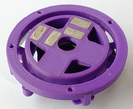
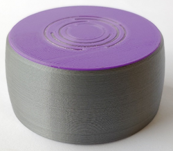
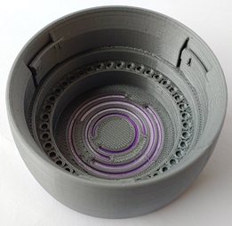
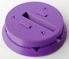
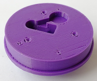
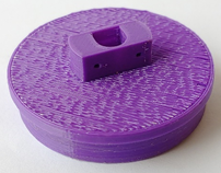
    Knob1

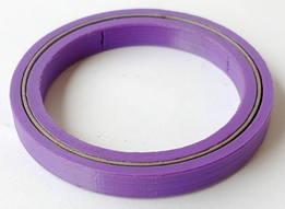
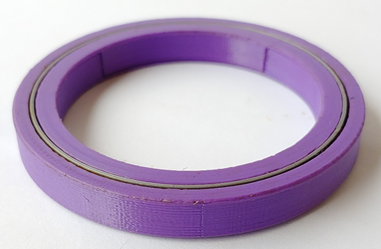
    Printed with three filaments (Purple, Transparent, Silver)

    Material – PLA

    Recommended infill % = >40


    Knob2

    Material – PLA

    Recommended infill % = >40


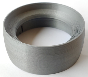
    Battery Holder

    Material – PLA

    Recommended infill % = >40


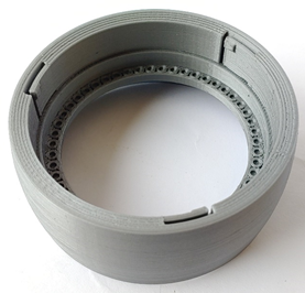
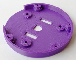
    Secondary Encoder Board Holder

    Material – PLA

    Recommended infill % = >40


    SpaceNav Mechanism Holder

    Material – PLA

    Recommended infill % = >50


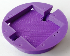
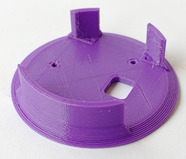
    Main Board Holder

    Material – PLA

    Recommended infill % = >70


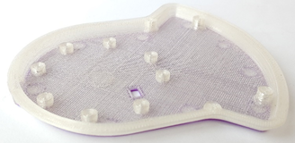
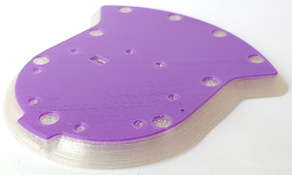
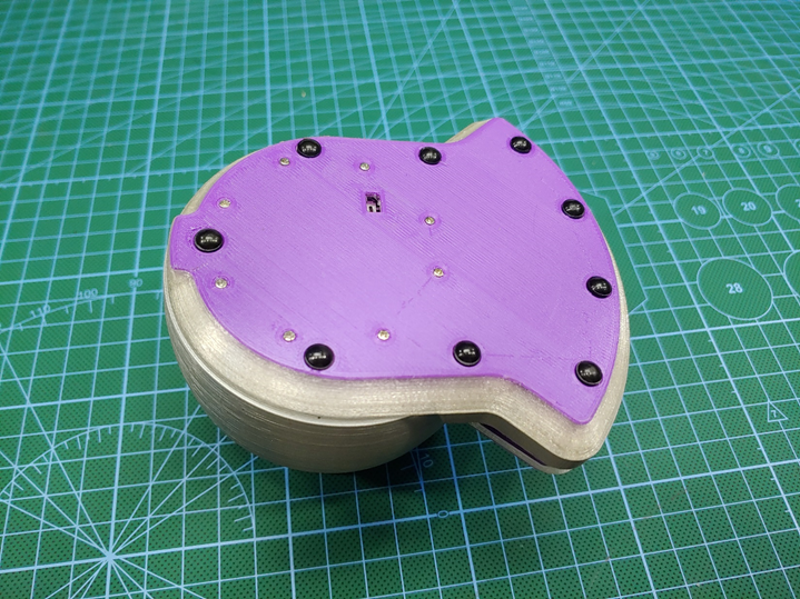
    Base

    Printed with two filaments (Purple, Transparent)

    Material – PLA

    Recommended infill % = >50


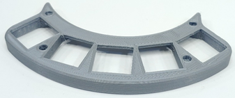
    Macro Key Holder

    Material – PLA

    Recommended infill % = >40


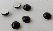
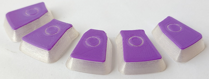
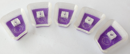
    Key Caps

    Printed with two filaments (Purple, Transparent)

    Material – PLA

    Recommended infill % = 100


  • 2
    Preparing To Assemble the Dial

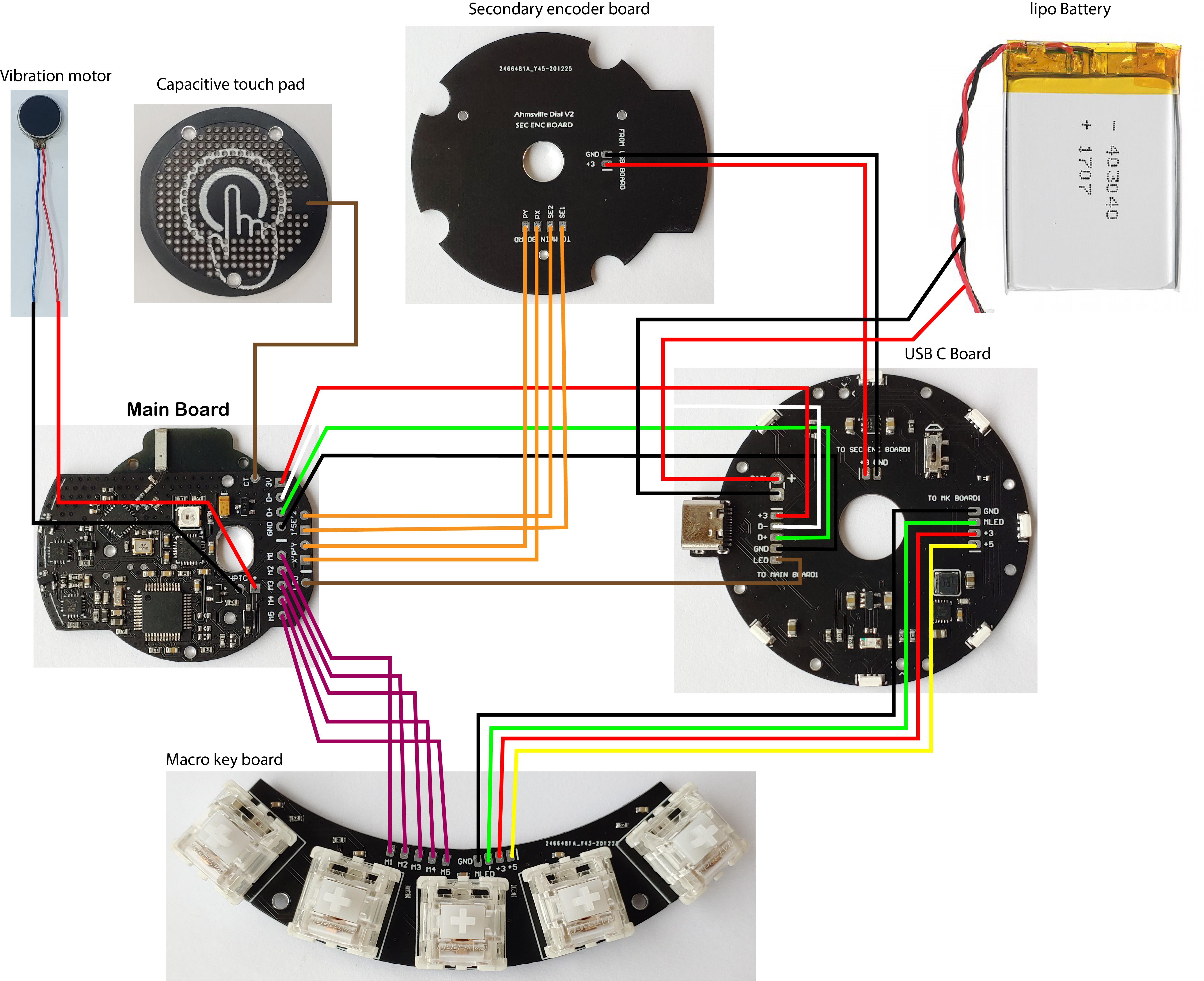
    Before starting the actual assembly, i recommend taking some time to study the wiring diagram, understanding the wiring diagram will make the assembly a lot easier.

    Wiring Diagram

  • 3
    Assembling the Dial

    Step 1

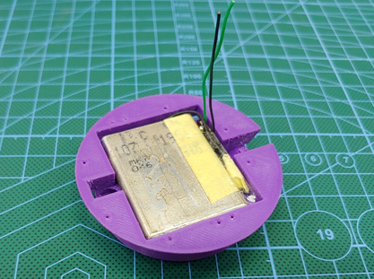
    Insert lipo battery into the battery holder


    Step 2

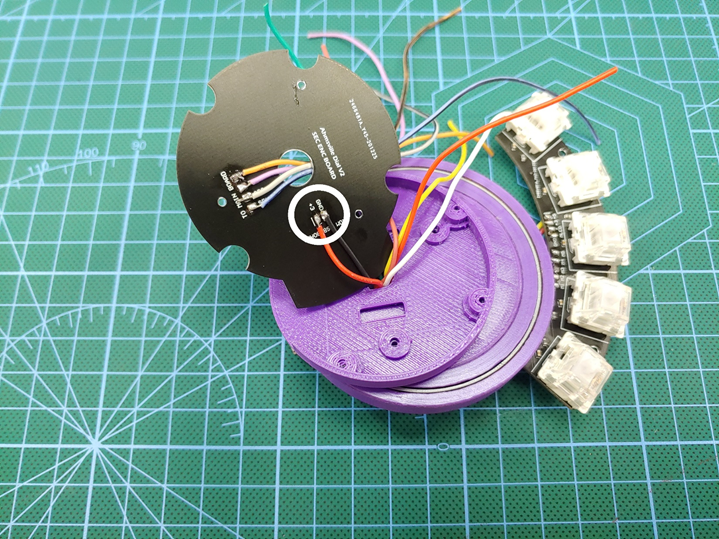
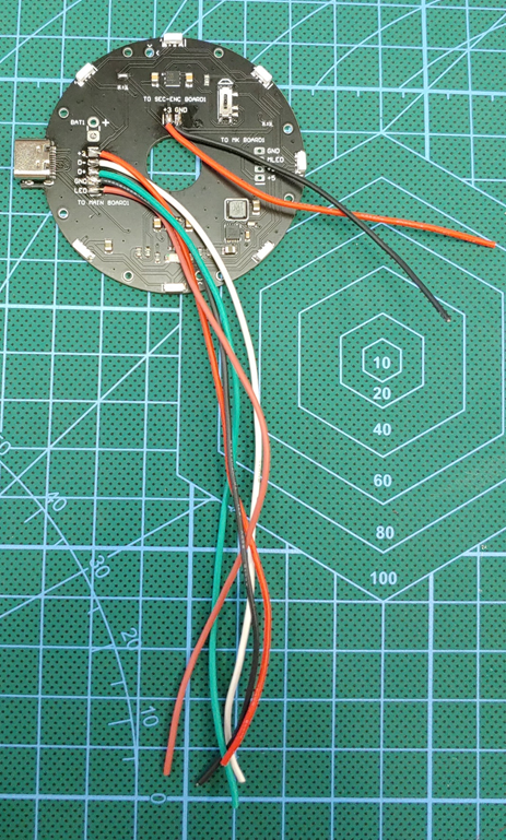
    Solder five 150mm wires to +3, D-, D+, GND, and LED (TO MAIN BOARD). 

    Solder two 85-90mm wires to +3 and GND (TO SEC-ENC BOARD)

    Step 3

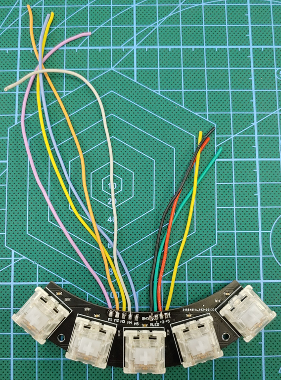
    Solder five 150mm wires to M1, M2, M3, M4 and M5 (TO MAIN BOARD).

    Solder four 85-90mm wires to +5, +3, MLED and GND (TO USB BOARD)


    Step 4

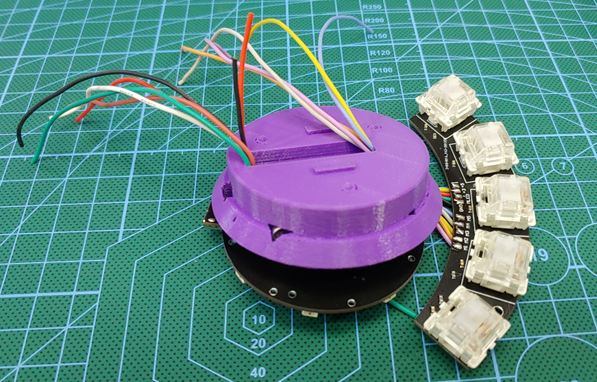
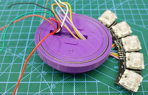
    Route wires through the USB board and the battery holder


    Step 5

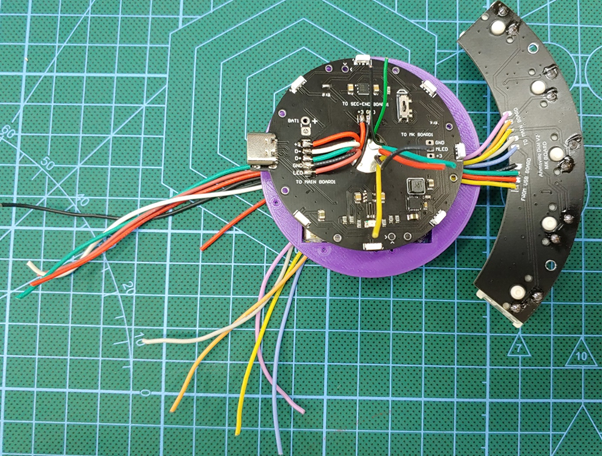
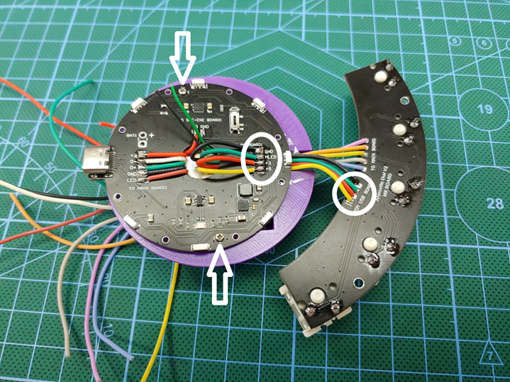
    Terminate +5, +3, MLED and GND wires from the macro key board to the USB board.

    Secure USB board with two m1.4x6mm screws.


    Step 6

    Install 6811 ball bearing on the battery holder


    Step 7

    Attach secondary encoder board holder, making sure to route all the wires through the center hole.


    Step 8

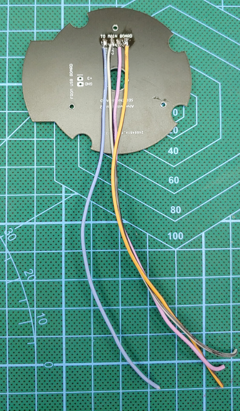
    Solder four wire to SE1, SE2, PX and PY.

    Take note of the connections using the wire colors as identifiers, you can write it down somewhere or simply take a picture of it.


    Step 9

    Terminate the short +3 and GND wires from the USB board to the Secondary encoder board, these wires provide power to the sec-enc board.


    Step 10

    Attach the secondary encoder board to the holder, making sure to route all 14 wires through the center hole.

    Secure the board and the holder with three m1.4x10mm screws.


    Step 11

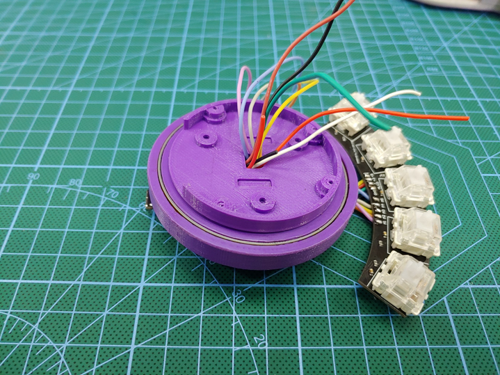
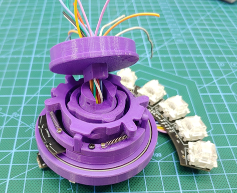
    Install SpaceNav Mechanism, making sure to route all 14 wires through the center hole.

    Secure the Mechanism with four m2x10mm screws.

    Step 12

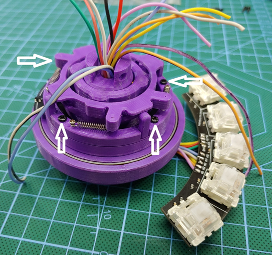
    Attach the Spacenav mech holder, making sure to route all 14 wires through the center hole.

    Secure the holder with two m1.4x10mm screw.


    Step 13

    Install vibration motor.


    Step 14

    Install 6809 ball bearing.


    Step 15

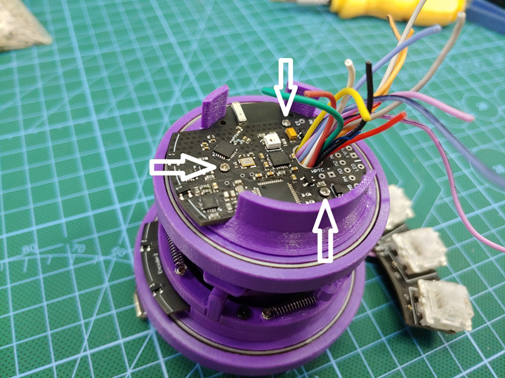
    Attach main board to the main board holder.


    Step 16

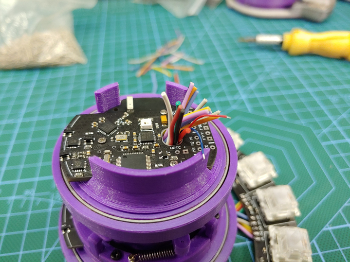
    Install the main board together with its holder, making sure to route all 14 wires and the vibration motor wires through the center hole.


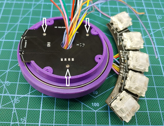
    Step 17

    Secure the main board and its holder using three m1.4x10mm screws.


    Step 18

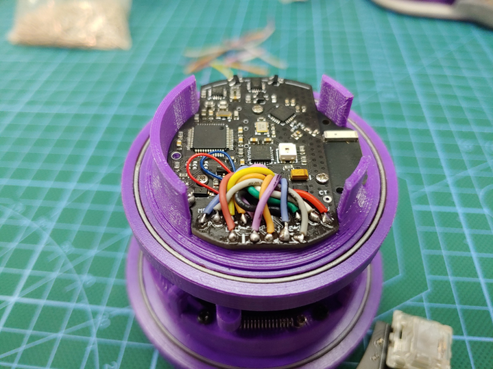
    Shorten all wires, be careful not to cut them too short.


    Step 19

    Terminate all wires to their appropriate spot, refer to the wiring diagram.


    Step 20

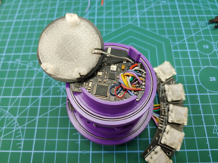
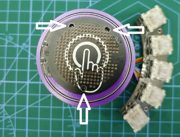
    Solder a wire to the capacitive touchpad and terminate it to the CT pin on the main board.


    Step 21

    Secure capacitive touchpad with three m1.4x10mm screws.

    Step 22

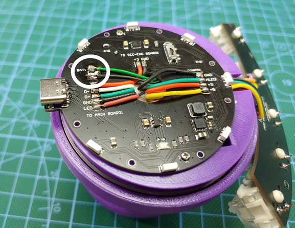
    Solder battery wires to the USB board.

    You may want to double check all your connections before doing this, make sure all your power connections are soldered to the right pins and with the right polarities.


    Step 23

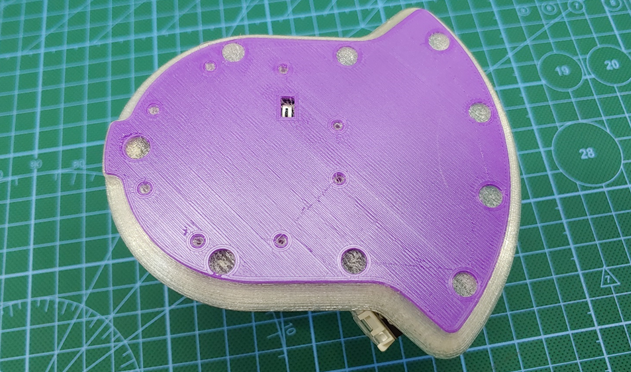
    Attach the base.

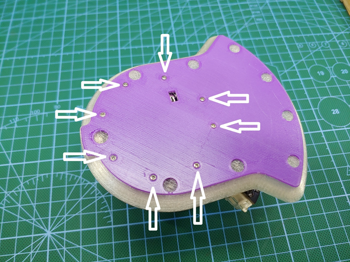
    Secure the base with eight m1.4x10mm screws.


    Step 24

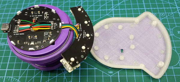
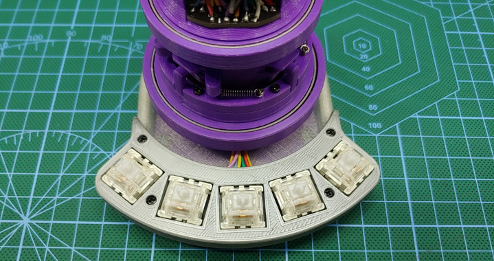
    Attach macro key board holder and secure it with four m2x8mm screws.


    Step 25

    Install the neodymium magnets on the knob, the magnets should be arranged with alternating poles next to each other.

    Depending on your 3D printer’s tolerance, you may or may not need to use superglue to secure the magnets.

    Step 26

    Attach the knob to the dial.

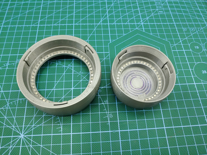
    the knob has three self-locking tabs that helps it to grab onto the bearing, so you just need to gently force it onto the bearing and push down until the knob seats in place.


    Step 27

    Install Key caps.


    Step 28

    Attach rubber base pads.


    Congratulations!!!


View all 4 instructions

Enjoy this project?

Share

Discussions

Similar Projects

Does this project spark your interest?

Become a member to follow this project and never miss any updates