Kevin Kadooka
-
3. First Light
05/30/2021 at 03:30 • 2 commentsI have a terrible, terrible habit - and that is speeding through a project without making detailed documentation of the process. Sometimes the momentum just builds and rather than pause to snap a picture or two - and just like that, the camera is already done! I did manage to take a few in-progress photos, though:
![]()
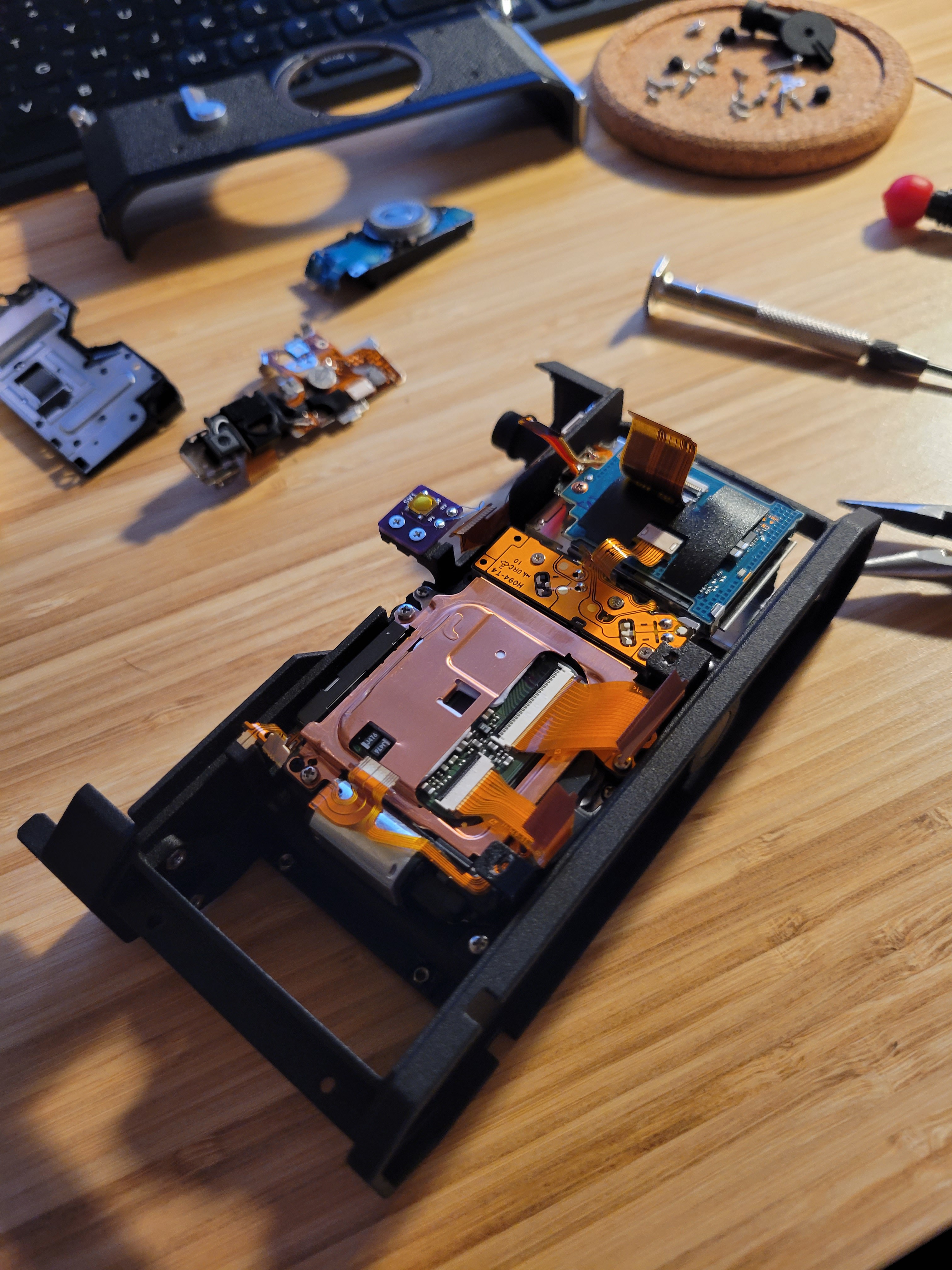
Shutter, sensor, and battery/SD assembly in place. The relocated playback button is also visible here, it's the purple OSHPark PCB in about the center of the frame. ![]()
The motherboard is in place, with most of the ribbon connectors hooked up. The one dangling off the motherboard connects to the LCD display, after the rear shell is mounted. The rear control panel has also been connected. ![]()
More detail of the broken out switchgear. The playback button (left) is actuated by the backlight compensation button on the Canon 7's top shell, the shutter button (center) aligns with the opening for the same, and the power switch (right) is a rotary DIP switch that lines up with the opening for the film advance lever. ![]()
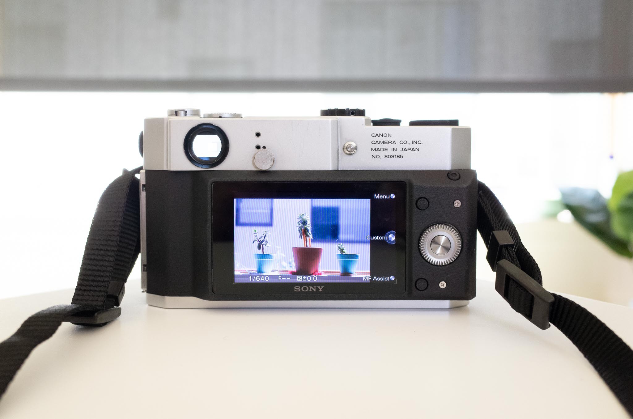
All buttoned up, and there are scarcely any hints that this is a digital camera. ![]()
Viewing from above, it becomes a little more obvious. You can see the modified shutter button and a power switch in place of the film advance lever. The sensor, motherboard, and screen cause the back of the camera to extend a little beyond the original envelope. ![]()
And from the back... Yup, that's a digital camera, all right. Some sample photos from the camera, using the Canon 50mm f/1.8 (the only LTM lens I own):
![]()
![]()
![]()
![]()
I'm not entirely sure if it's the nature of the lens, but it certainly is not very sharp! It improves a little bit when stopped down, but off-center softness is very evident when focusing on distant subjects. I suspect that the sensor is skewed a bit and doesn't align perfectly with the image plane. The sensor is held in place rather lackadaisically without any real measures to ensure alignment other than relying on the dimensional accuracy of the 3D print. One of these days I'll need to place a depth gauge between the sensor and the lens flange, and try to get it dialed in. But for now, I'm just glad that it works!
-
2. Progress, and "for want of a nail"
05/29/2021 at 06:34 • 0 commentsAh, finally - some progress to report. All of the parts and pieces are in at last. The pieces I was anticipating the most were definitely the 3D printed pieces. All were printed in Shapeways' MJF plastic, which I have had numerous excellent experiences with. I used their medium-fast service and I had parts on my doorstep within 2 weeks. I also ordered one translucent SLA part (a replacement frameline window for the Canon 7 - mine crumbled into dust during disassembly), which took a couple more days to print and be processed. If I had printed everything in MJF, I'm sure it would have been even faster.
![]()
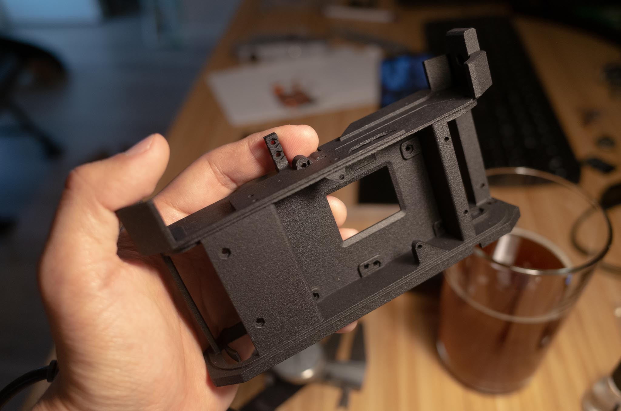
The main chassis. ![]()
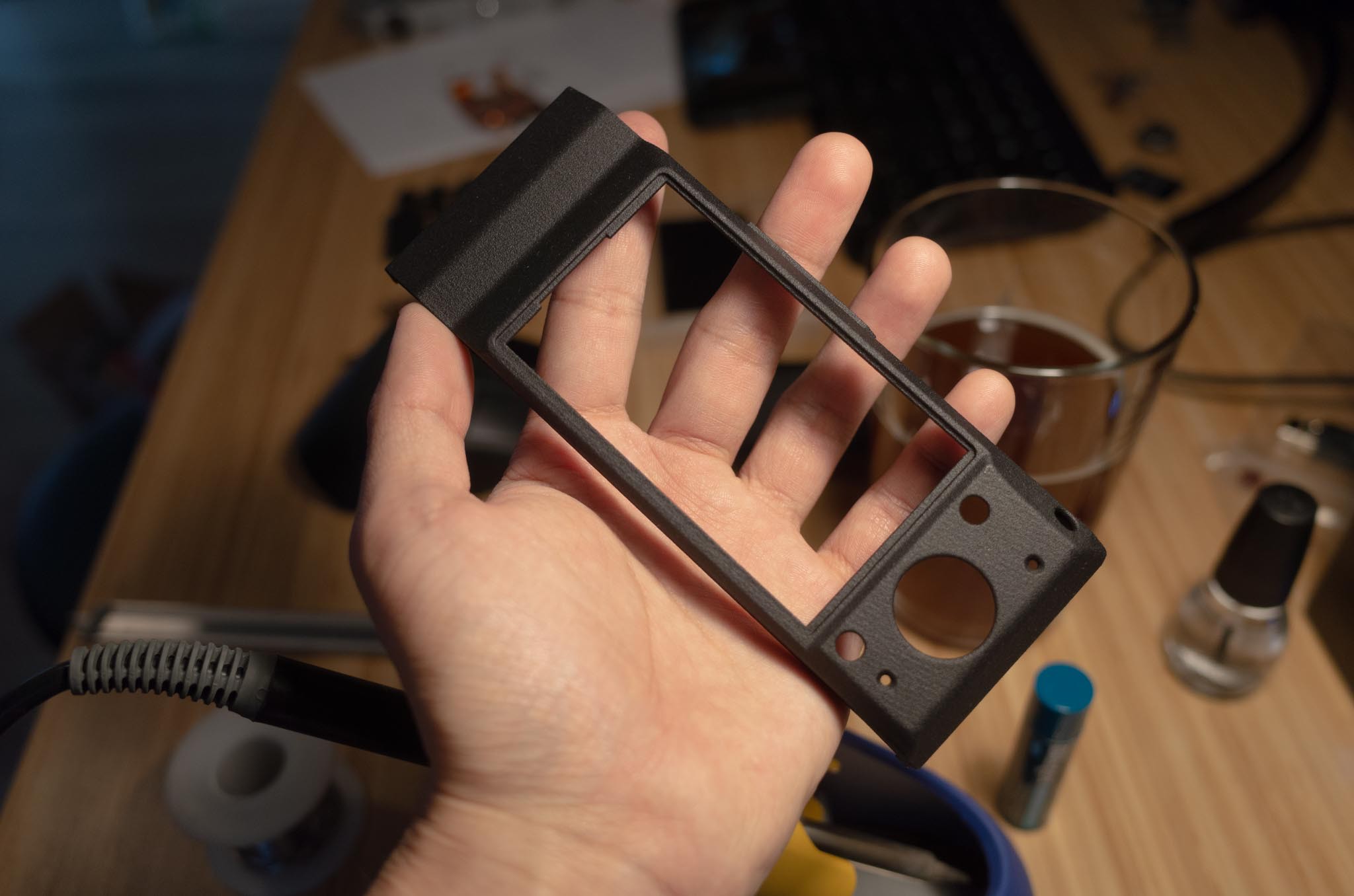
The rear shell. ![]()
Various bits and pieces, held together with sprues. It's MUCH cheaper to print this way! I've already started the process of putting the camera together, but there have been two major setbacks:
- Something in the NEX-5 donor electronics gave up the ghost. I've not been so kind to it (generally manhandling the electronics without any anti-static measures) I think the nail in the coffin was plugging in the battery without properly insulating all of the flying wires and exposed PCBs. A short probably occurred which has sent the camera to an early grave. RIP, you will be missed. Anyway, I bought a new donor camera - there is no shortage of these things.
- I bought the wrong freaking size of M1.6 hex nuts. This is quite a sordid tale. First, I wanted some thin M1.6 hex nuts, under DIN 439B standard. Those things are unobtanium, it seems. And when they are available, sellers want an arm and a leg for them ($3-4 a pop! And I stupidly designed this thing needing 26 of them...). I finally found them at a decent price, but the seller waited a full week to tell me that they were out of stock and not planning on backordering any. So, I decided to suck it up and buy some regular M1.6 hex nuts (the DIN 934B standard) and shave them down where necessary (there are only a few places where their thickness is actually important). I decided to go the cheapest possible route and buy some on Amazon Prime, not realizing that they were of a nonstandard size. See, standard M1.6 nuts are nominally 3.2 mm flat-to-flat and 1.3 mm thick. These ones I got on Amazon were 2.5 mm flat-to-flat and 1.5 mm thick. This meant that the hex-shaped features I designed in the 3D prints did not hold prevent them from rotating at all. A copious amount of CA glue was needed to fill in the gaps and hold the nuts in place, which worked half of the time. Another quarter of the time, the nuts would simply break loose under torque, or a stray glob of CA glue would gum up the threads. The lesson here? Always check availability of components before you design around them. I took the availability of a simple hex nut for granted, and it keeps biting me in the ass (hence the title).
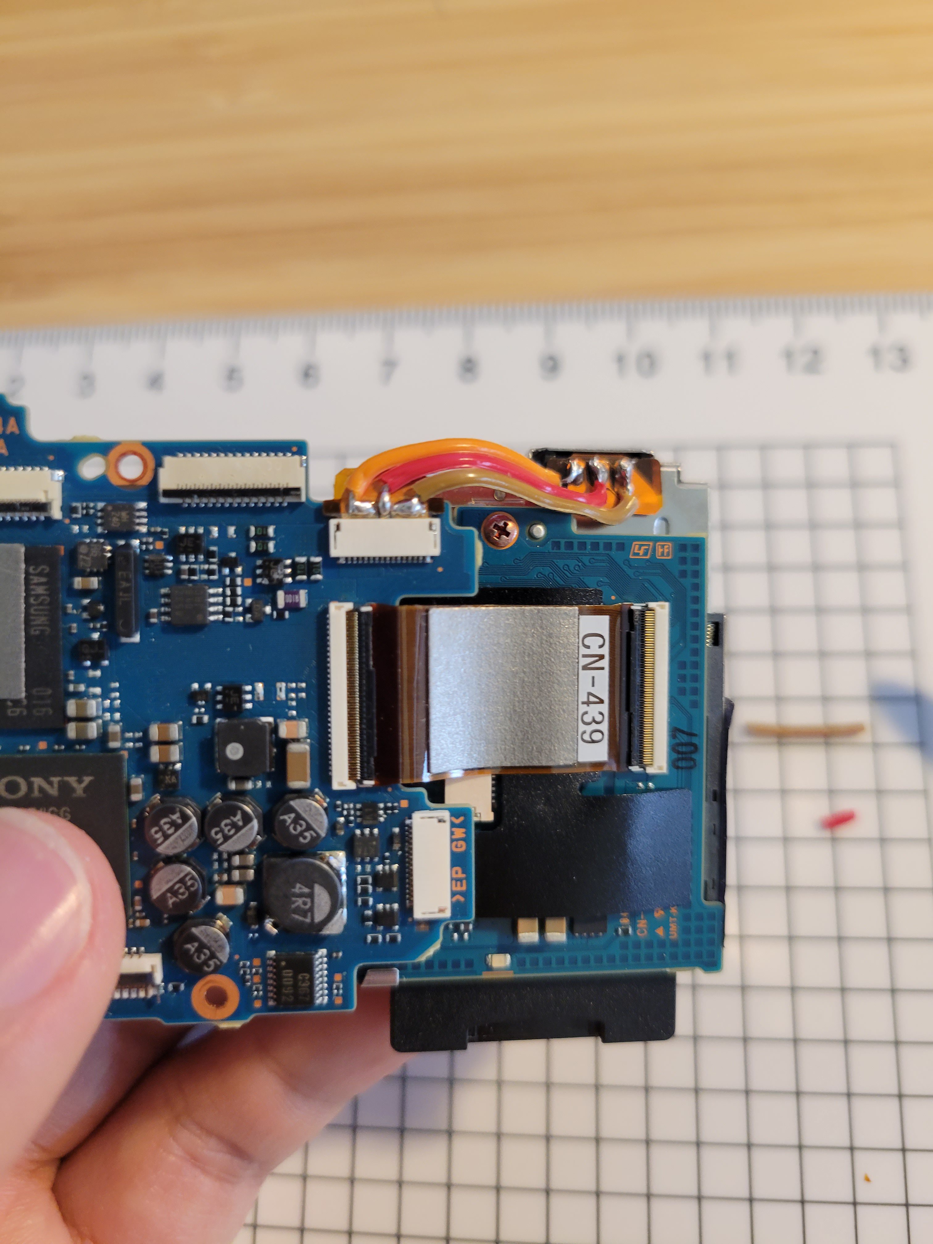
There was some success, however, with doing some of the electrical setup for the conversion. First, a bespoke solution is needed to connect the battery to the motherboard. To fit inside the Canon 7, the battery compartment of the NEX has to be rotated 90 degrees and sit just behind the motherboard, as shown below. The original flex connector is not meant to contort in such ways, so I snipped off the end and soldered 3 strands of a flat ribbon cable between it and the battery contacts. It's a tedious and careful job to strip away enough of the polyamide insulation on the flex circuit to expose enough bare area to solder to.
![]()
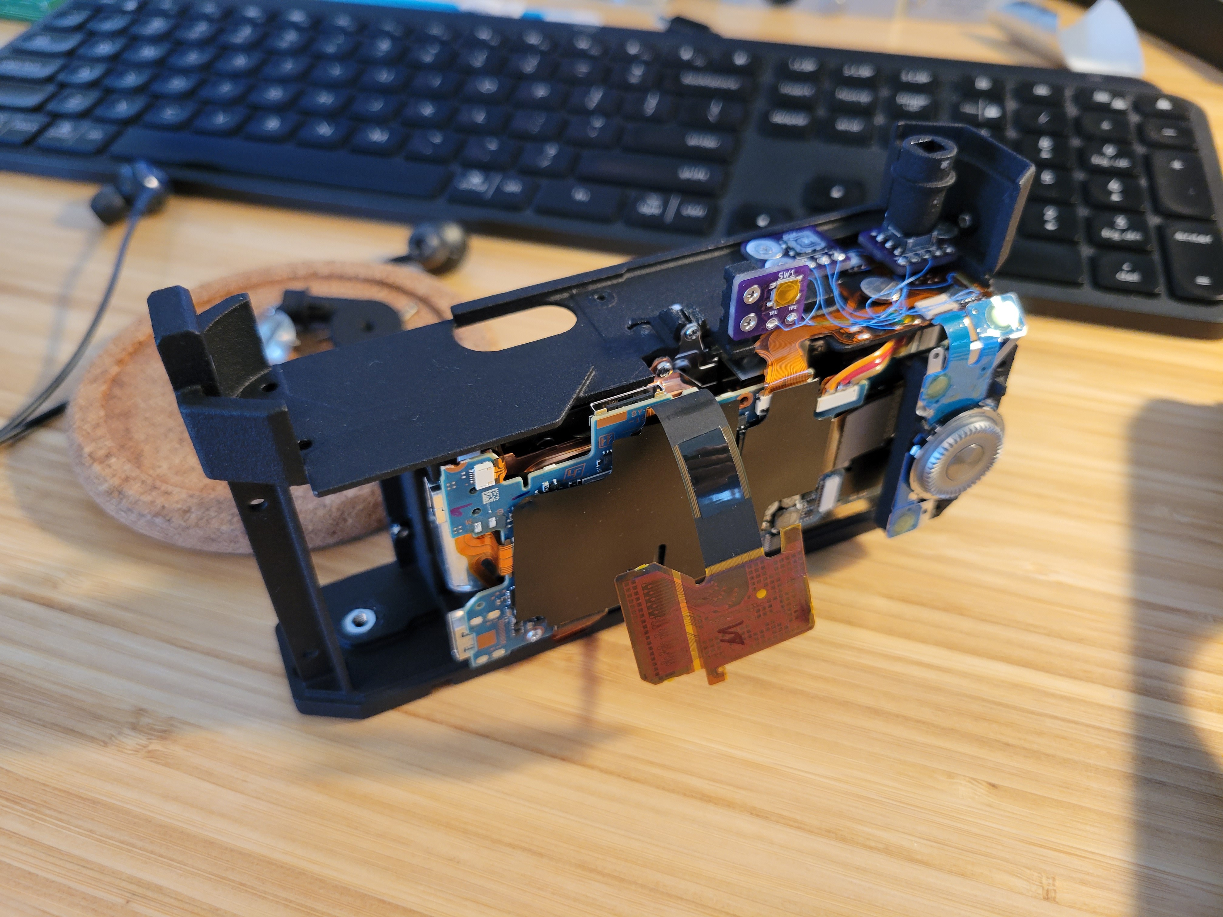
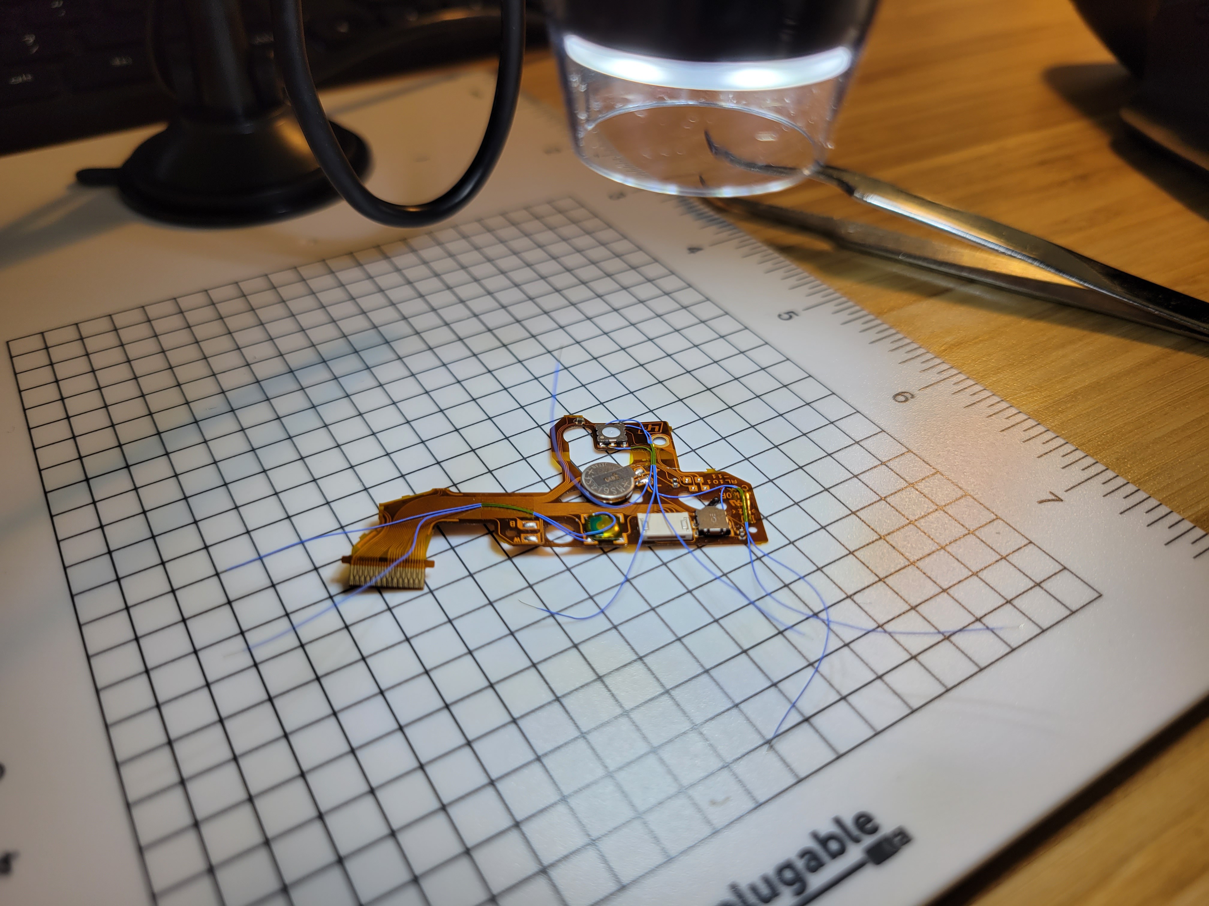
A not-so elegant solution, but it works. The top flex circuit of the NEX has some very important features: it holds the power switch, shutter button, and a button to enter playback mode. These will all be "broken out" via flying wires to locations easily accessible under the Canon 7's top shell (the exploded diagrams in the last entry may help to explain this). More tedium, but after a bunch of squinting and careful tweezer action, 38 AWG leads have been attached to the proper points on the flex circuit:
![]()
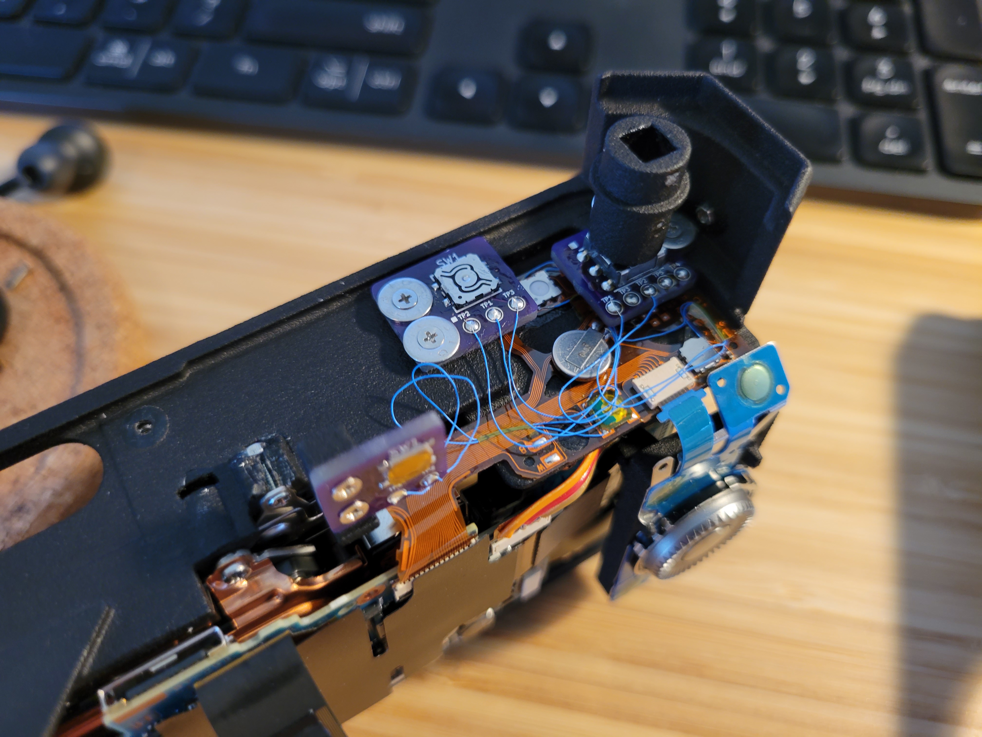
Again, not a very elegant solution but it gets the job done. For reference, these are the specific points that need to be broken out:
![]()
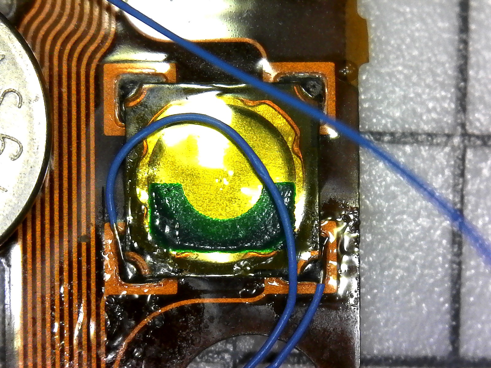
On the playback button, two leads go to another remote tactile switch. ![]()
This is the shutter button, which is a two-position tactile switch. The top left and bottom right are common. Bottom left shorts to common on the first depression. Top right shorts to common on the second depression. ![]()
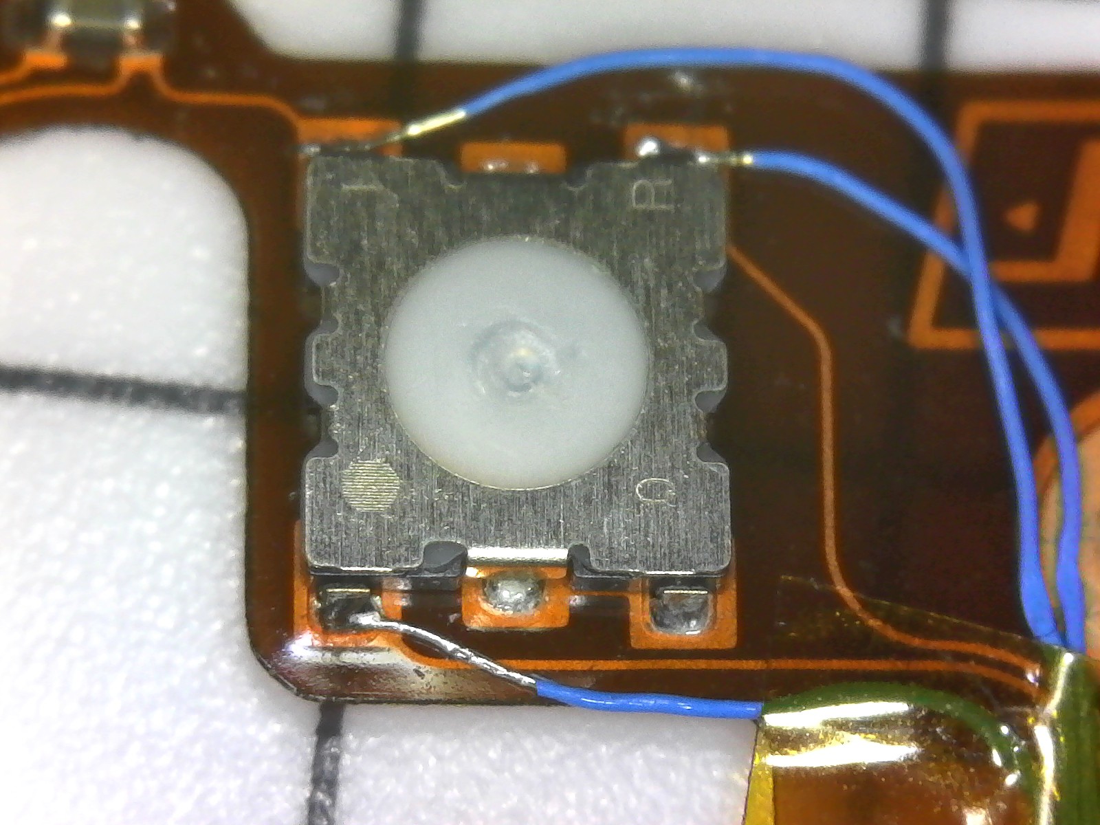
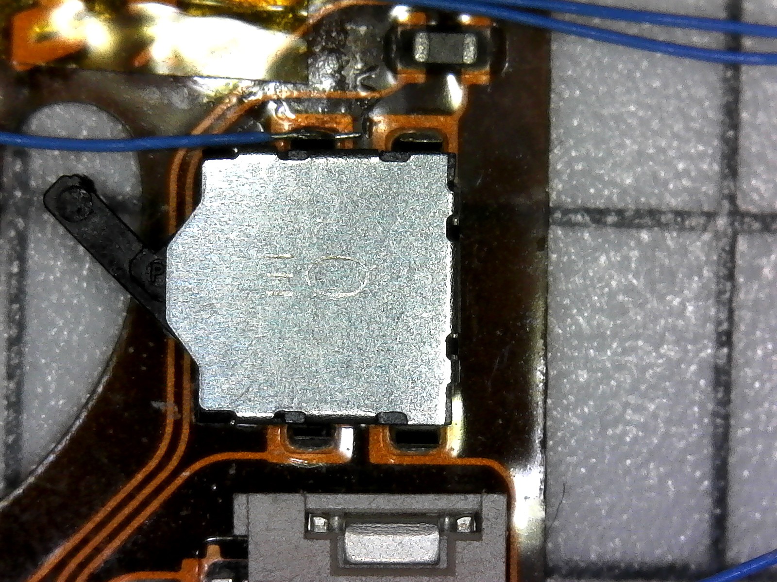
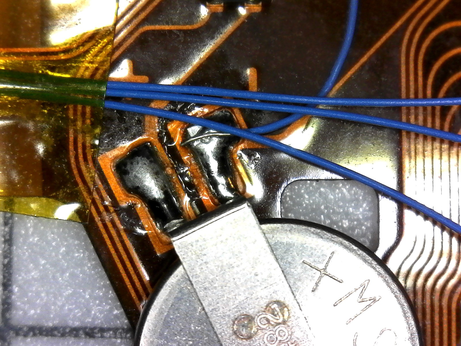
Here's the power switch. I only soldered one wire here, because the other terminals are blocked by a capacitor (top right) and the ribbon connector for the rear control panel (bottom). ![]()
Instead it is much much easier to solder the other power switch wire to one terminal of the little coin cell battery on the top ribbon. That's all for now. Will have a more substantial update soon, as the camera continues to come together. -
1. Introduction
05/17/2021 at 01:41 • 0 commentsHere's the idea. Let's make a digital rangefinder camera by combining the electronic bits of a Sony NEX-5 (the OG version circa 2010-2011) and the body and rangefinder unit pulled from a Canon 7.
I should point off off the bat that this isn't something new - there have been various successful efforts to combine film cameras and digital sensors (see: https://frankencamera.wordpress.com/2014/08/30/the-making-of-frankencamera/). My tenuous claim to originality is that nobody (to my knowledge) has done this to an Leica Thread Mount (LTM) rangefinder, let alone the Canon 7.
Perhaps the best way to introduce this project would be to answer the "whys":
- Why build a digital rangefinder camera? I don't know, for fun, I guess? Digital rangefinder cameras exist, and if you were so motivated, you could just buy one off the shelf. However, the cheapest regular production digital rangefinder is probably the Epson RD-1 (which had a heroically long production run for a digital camera, from 2004-2014) - which you would struggle to find for under $1,000 on eBay. All for 6.1 megapixels. On the other end of the spectrum you have the PIXII ($3,300, with... interesting reviews) or the Leica M8 or later, which when new, will cost well north of $5,000. Before being usurped by the single-lens reflex, rangefinders were the norm. These days they are novel and unique, offering a different shooting experience. This project should cost much, much less than any of the aforementioned cameras, and might open that experience to those who don't have wads of cash burning Leica-sized holes in their pockets, and don't mind doing a little bit of tinkering.
- Why the Canon 7? Well, there are several reasons:
- They are cheap - you can find "for parts" cameras on eBay for as little as $50, and working examples are closer to $150, including shipping.
- They are plentiful - Canon made well over 100,000 of these cameras in the 1960's and 70's, so I don't feel too bad about chopping one up.
- The viewfinder/rangefinder optics comprise a single self-contained module. This makes it exceedingly easy to work with without fears of screwing up the optical alignment.
- Why the Sony NEX-5? Again, a few reasons:
- They are cheap - used examples can be found around $100, sometimes less.
- They are simple inside - Sony made this camera extremely easy to disassemble, by modern standards.
- This camera has been used for film-to-digital camera conversions before, so I don't have to tread through unknown territory. It's been done before, and people like Oliver (maker of the Frankencameras) have done a great job of documenting their work.
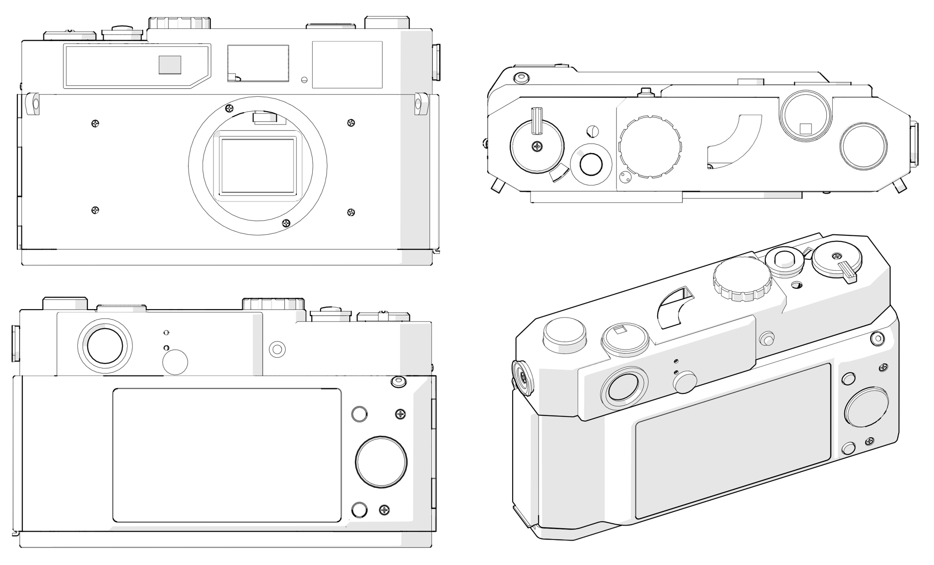
Based on others' work, I was feeling pretty confident that shoehorning this would work out. But still, I did a bit of research before buying parts. Repair manuals for both the Canon 7 and NEX-5 are available online (and free, with a little Googling) and are great resources for figuring out how things fit together. The NEX-5 also has vector drawings of the camera in various states of disassembly, which appear to be true to scale - which I used to make some mockups. Both the NEX and 7 are very prolific cameras, so there is an abundance of repair walkthroughs and teardowns showing off their guts - all good fuel for the imagination when considering how things will fit together.
![]()
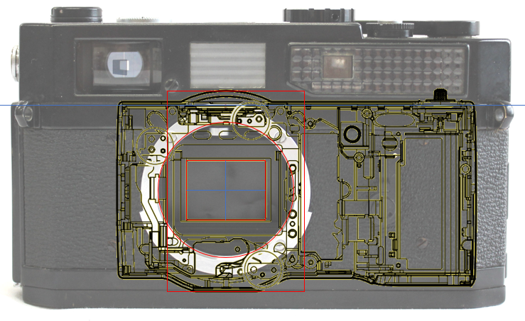
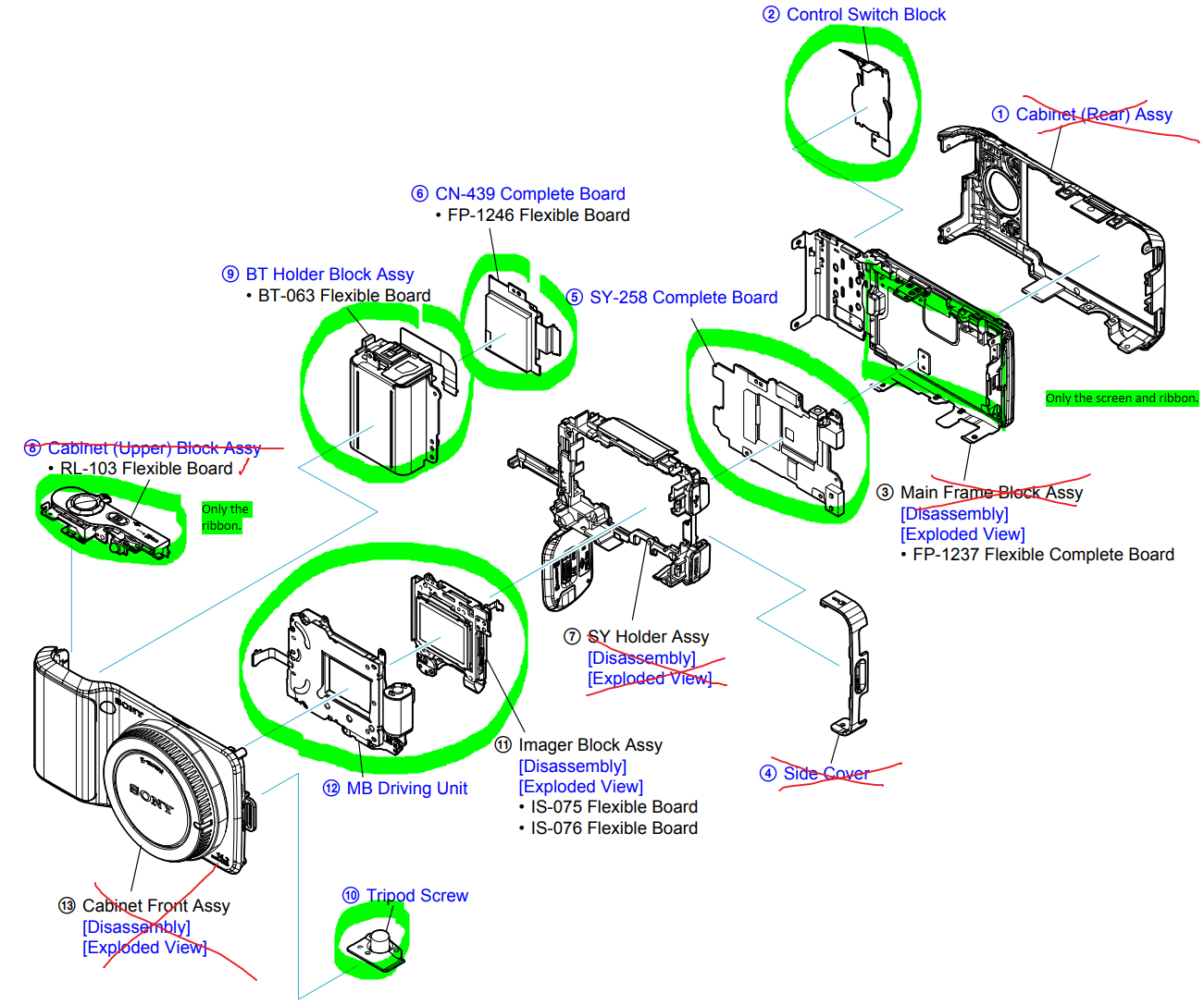
A mockup showing how parts of the NEX would fit inside of the 7. A marked up excerpt from the repair manual, showing which parts of the NEX would be harvested. I happened upon a 7 and an NEX-5 on eBay for $65 and $80, respectively. Both were in pretty well-used condition, and the 7 had recently undergone some surgery to fix a dislodged beamsplitter for the framelines... which immediately undid itself during transit. So, I had the opportunity to get familiar with the optical layout of the 7. Nothing a well-placed dab or two of super glue couldn't fix.
![]()
The donor NEX-5. Works perfectly, but a little rough around the edges. ![]()
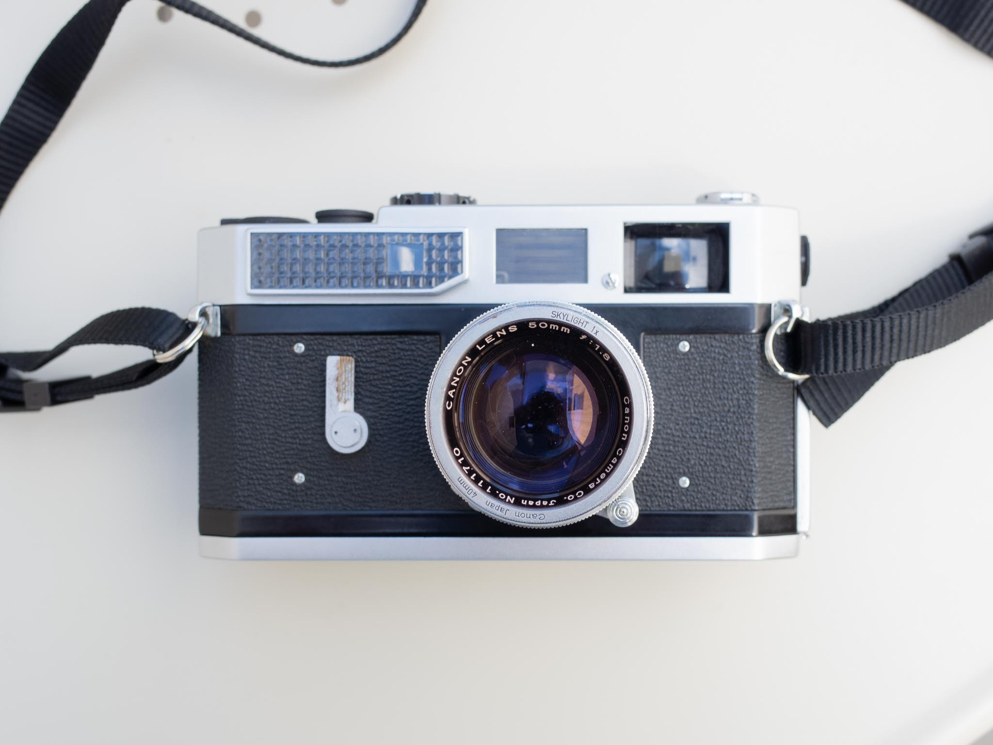
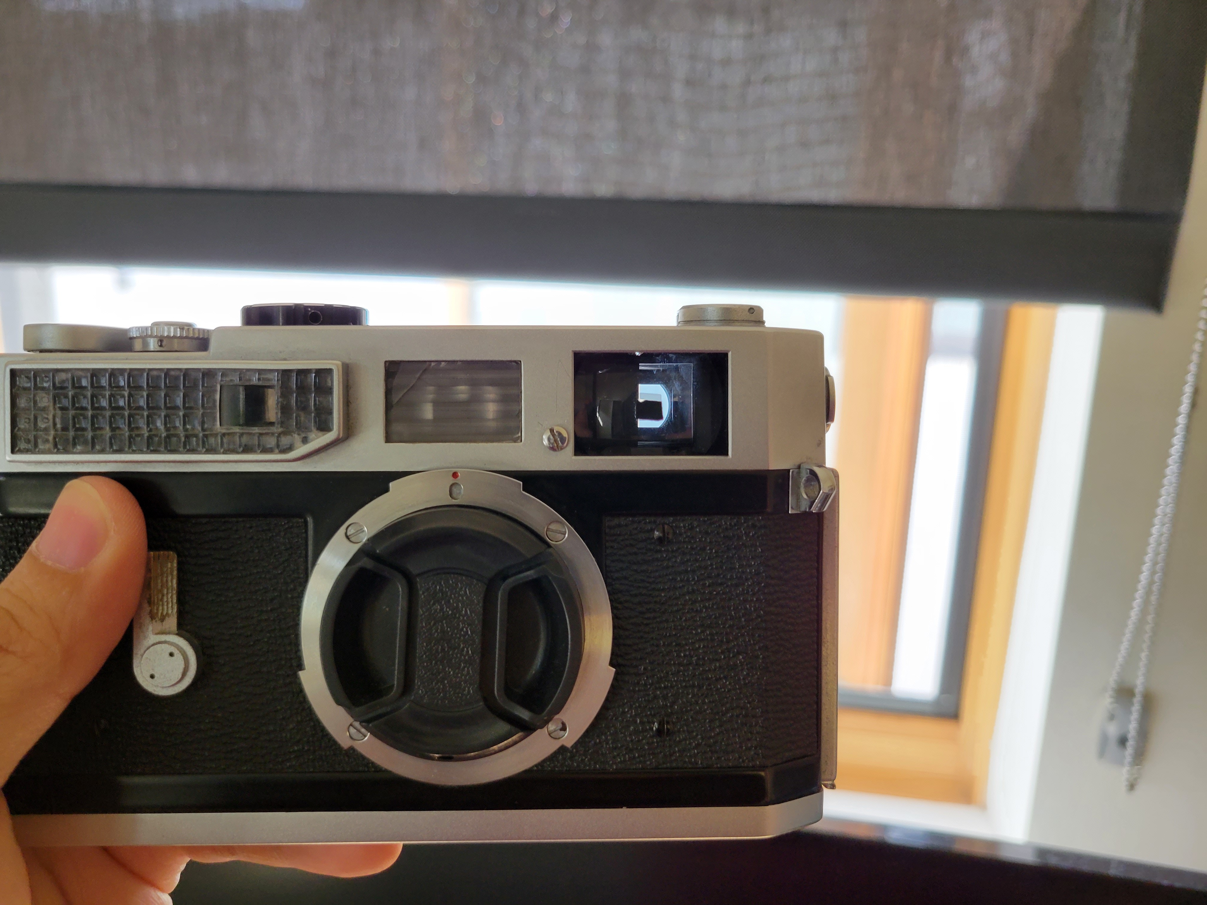
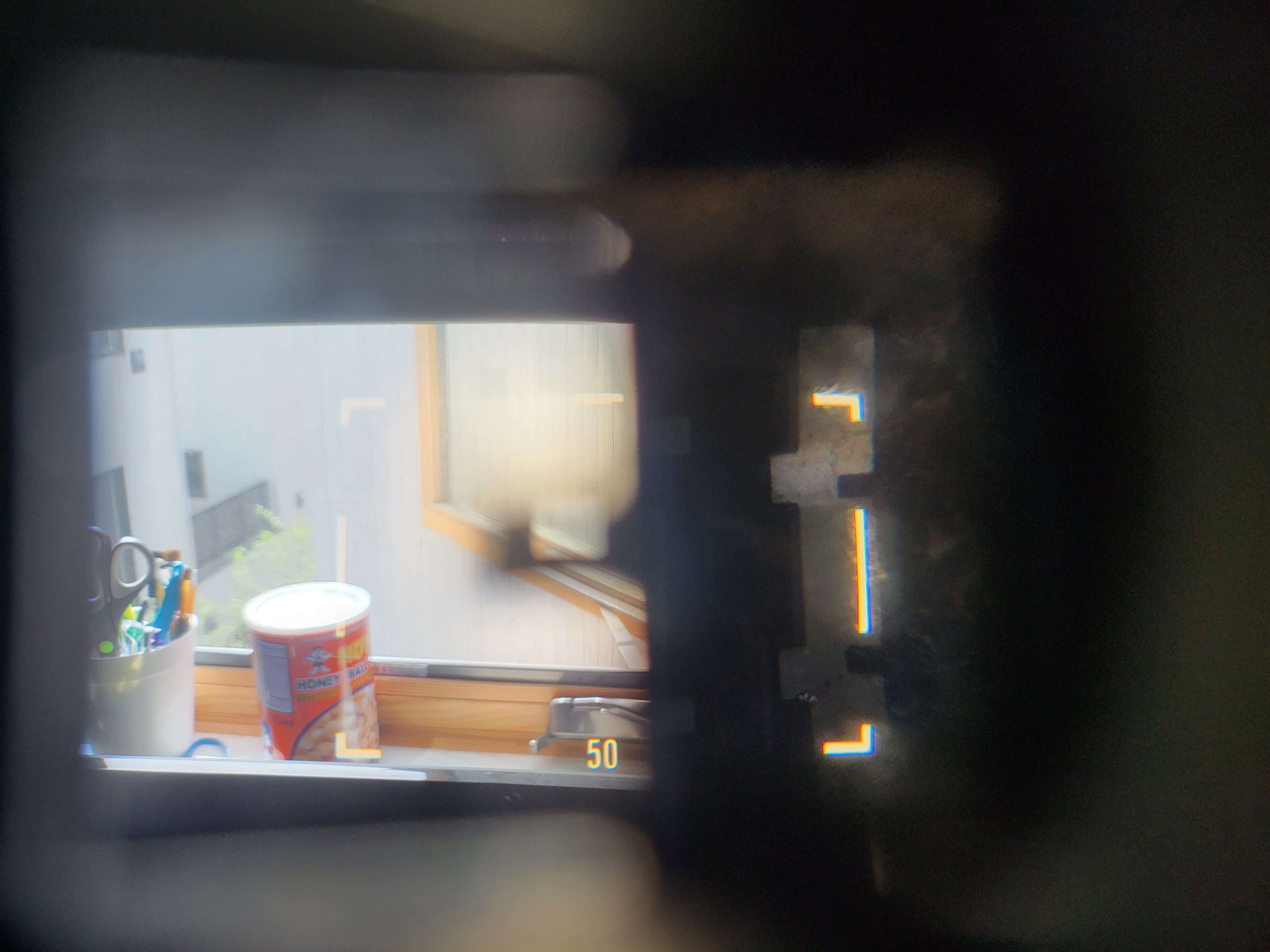
The donor Canon 7. It's no beauty queen. Hang on, something's wrong in the viewfinder... ![]()
Yup, something is definitely amiss. ![]()
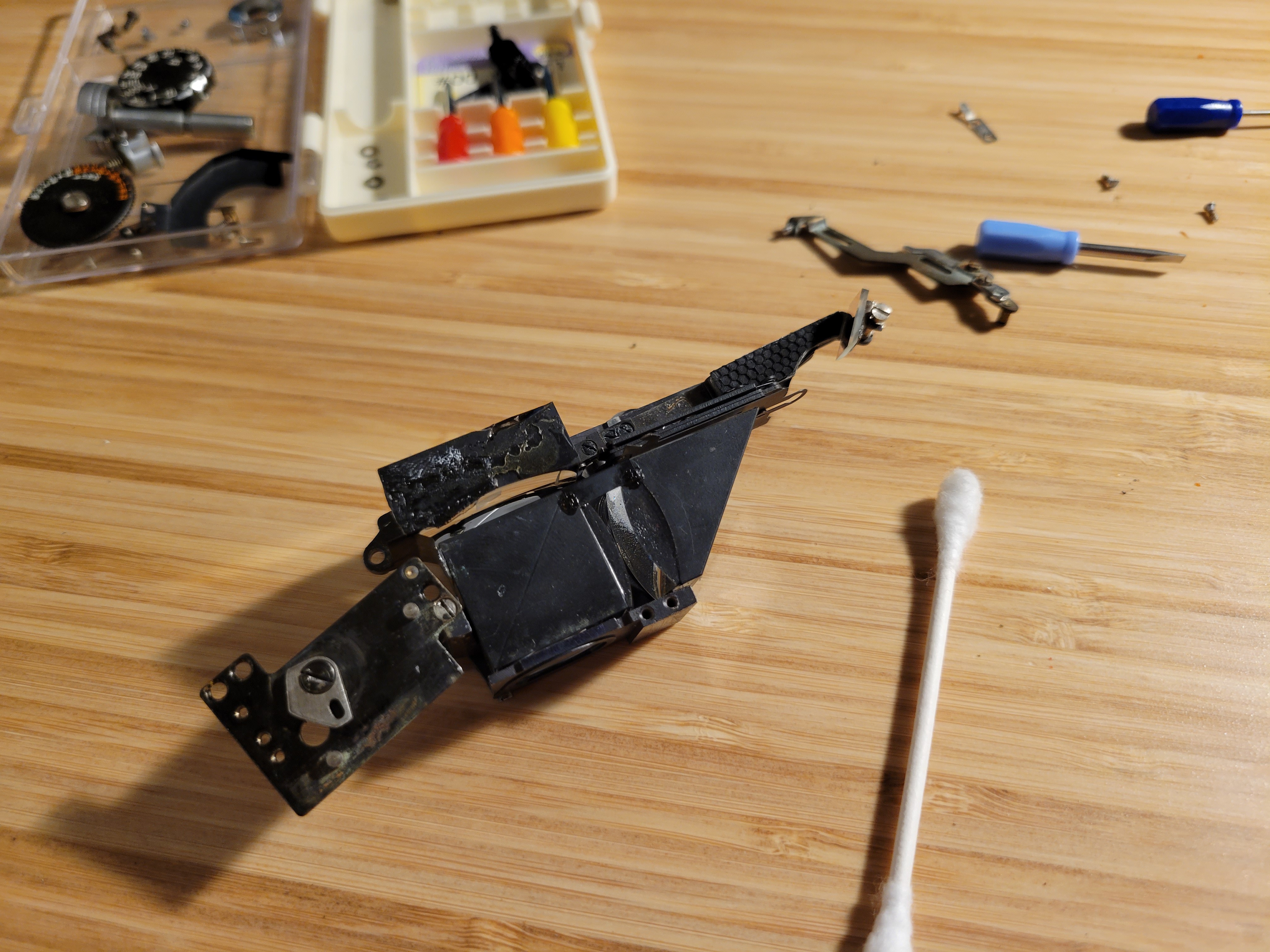
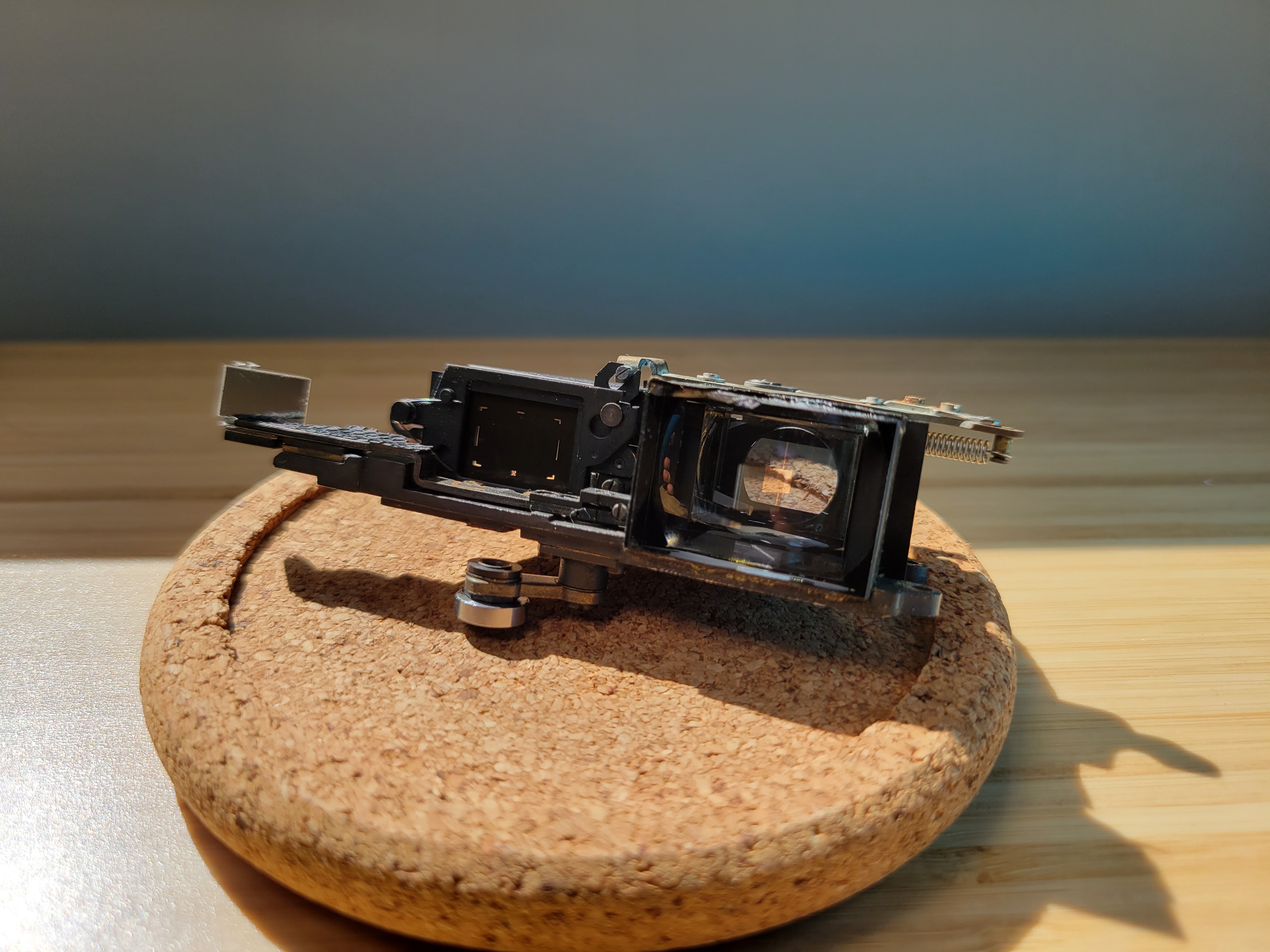
The beamsplitter for the framelines, the black cuboid mass in the middle, rattled loose along with a light shield. ![]()
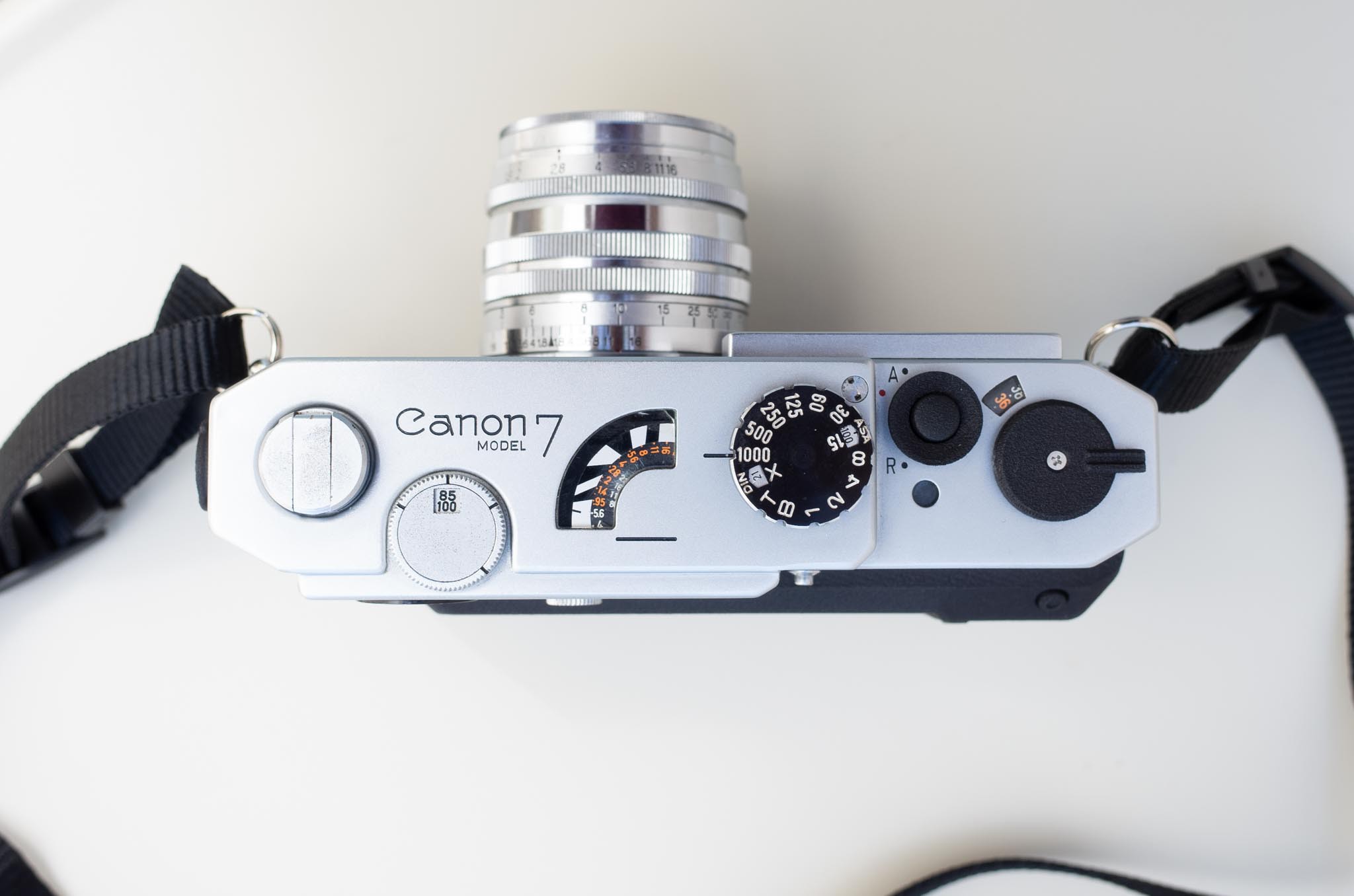
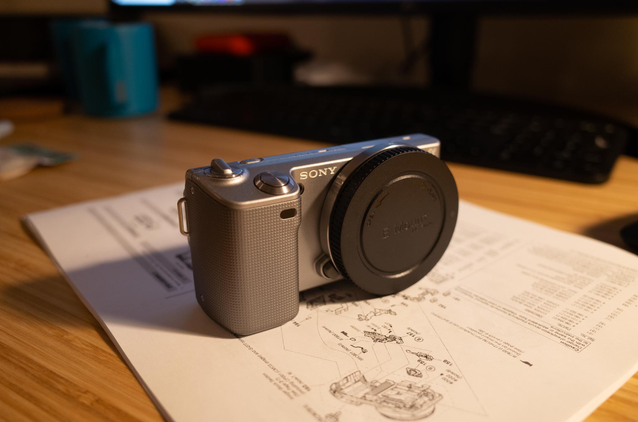
A bit of super glue and it's right as rain again. Note how the entire VF/RF assembly comes out of the camera in a self-contained module. Makes such repair a piece of cake! Anyway, it's been about a month since receiving the cameras, and they've been thoroughly hacked apart, measured, and modeled up in Solidworks. From the front, it looks pretty much like a Canon 7. Working around to the back, well, it looks a lot like a NEX-5 was grafted to the back - what, with the layout of the screens and the buttons, and all.
![]()
With the exception of the rangefinder/viewfinder unit, most of the Canon 7's internals end up in the scrap heap. A brand new chassis has been designed to accommodate the NEX's entrails. Here's my best IKEA imitation showing how the various parts fit together:
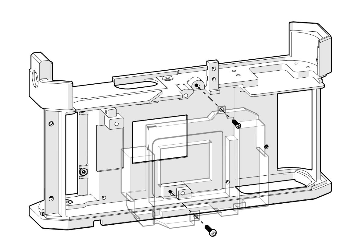
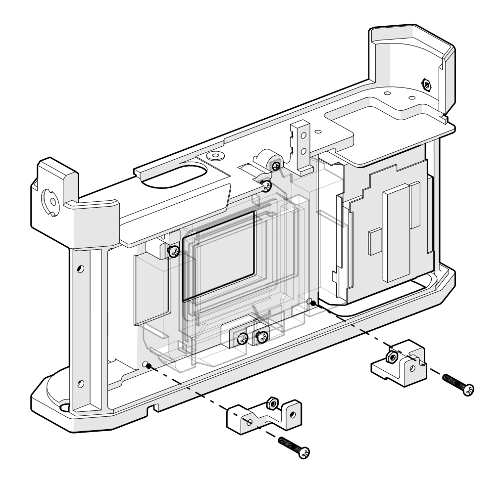
1. The shutter unit (transparent in the below image) is mounted to the chassis with some tiny machine screws.
![]()
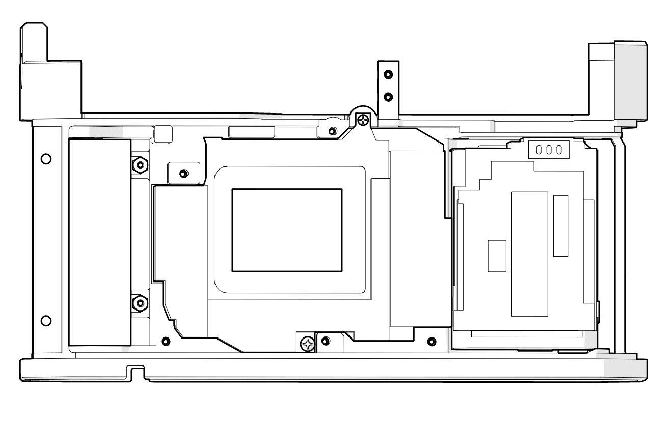
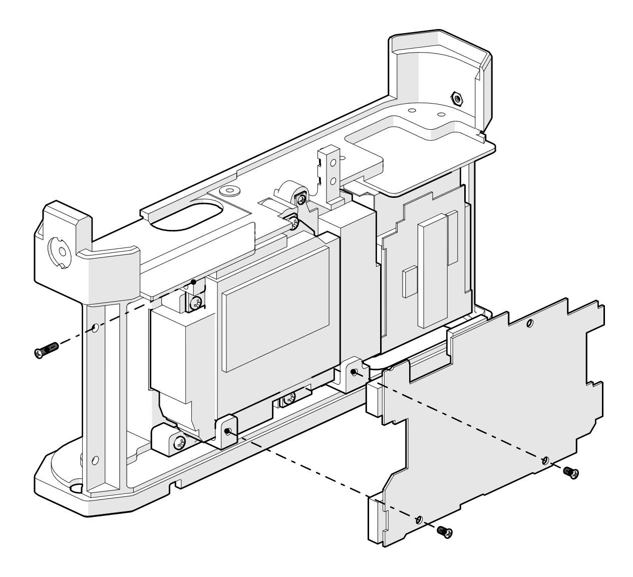
2. The battery "cage" and SD card unit are fixed to the chassis using double-sided adhesive.
![]()
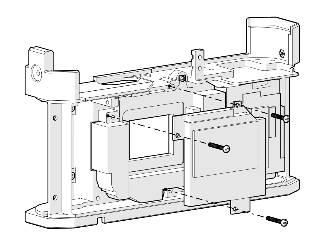
3. The image sensor sits atop the sensor, fixed to the chassis via more tiny machine screws.
![]()
4. Standoffs provide an attachment point between the chassis and the motherboard.
![]()
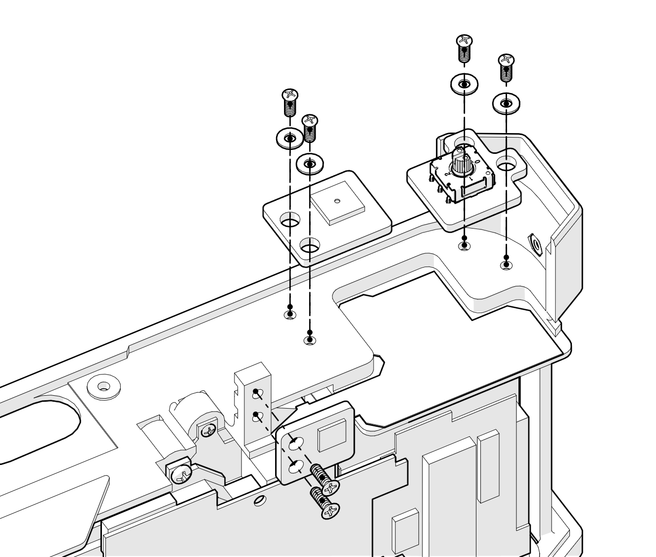
5. The motherboard is mounted to the standoffs.
![]() 6. The NEX top control panel ribbon is fixed to the chassis using double sided tape. Breakout boards are mounted above the original ribbon and connected via tiny 38 AWG flying wires. The 3 PCBs basically just reposition the playback button (bottom), shutter button (center), and power switch (right). The point of relocating these buttons is to position them with access points in the Canon 7 top shell.
6. The NEX top control panel ribbon is fixed to the chassis using double sided tape. Breakout boards are mounted above the original ribbon and connected via tiny 38 AWG flying wires. The 3 PCBs basically just reposition the playback button (bottom), shutter button (center), and power switch (right). The point of relocating these buttons is to position them with access points in the Canon 7 top shell.![]()
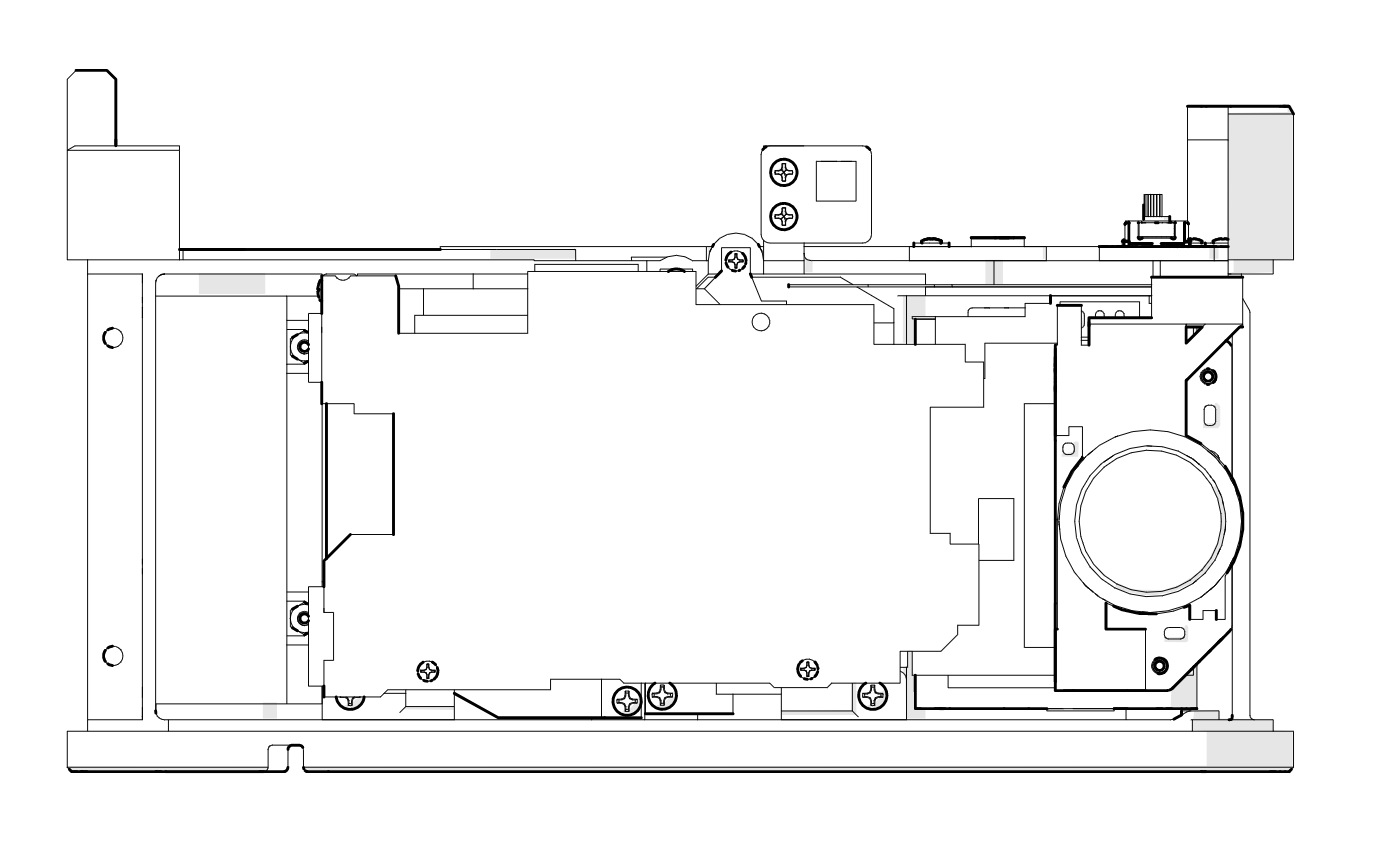
7. The NEX rear control panel sits above the battery cage and SD module.
![]()
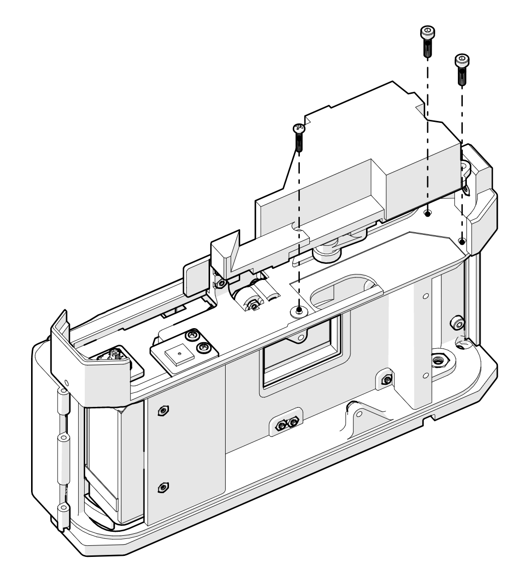
8. The rear shell encloses the rear of the camera and holds the LCD display in place.
![]()
9. The RF/VF unit is affixed to the chassis, and the rangefinder cam slips through a slot into the exposure changer.
![]()
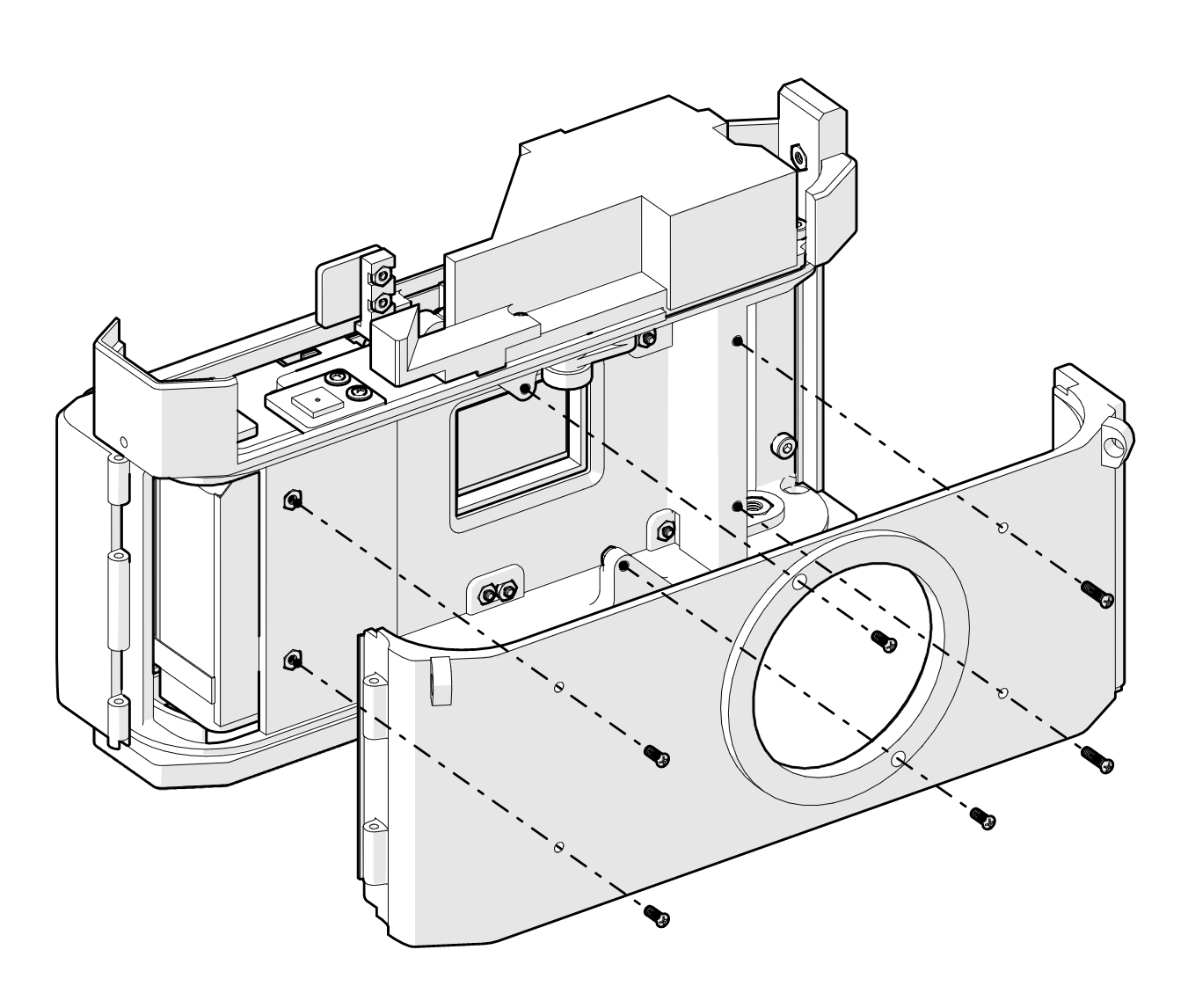
10. The original front shell from the Canon 7 is affixed to the main chassis with another myriad of tiny machine screws.
![]()
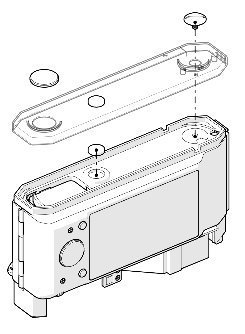
11. The original bottom shell from the Canon 7 is secured to the bottom shell using an extra-wide slotted flange screw (right) which can be removed with a suitably sized coin. The right side is secured with two extra-strong neodymium magnets. The hole on the left which would usually provide access to the tripod mount has been covered with a panel cover - no tripod mount on this camera! Just hold the camera really still. It's that simple.
![]()
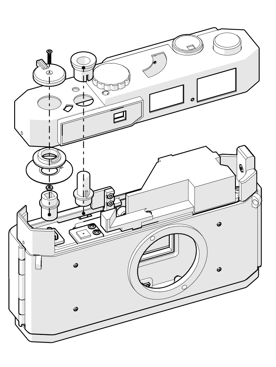
12. The top plate is carried over from the Canon 7, but a bunch of original components are used for the power switch (left), which replaces the film winder, and the shutter button (second from left).
![]()
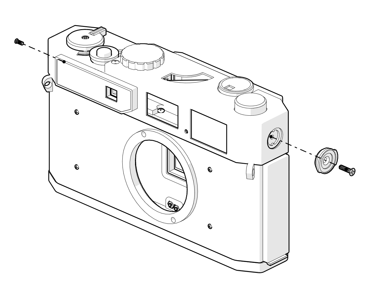
13. Finally, the top shell is secured by a couple of screws and a replica of the original flash bayonet.
![]()
All of the various parts and pieces have been ordered and should arrive later this week or early next week. I'm excited to get started and share progress!
Canon 7 Rangefinder Digital Conversion
Converting Canon's 1960's workhorse rangefinder into an APS-C digital camera.


 6. The NEX top control panel ribbon is fixed to the chassis using double sided tape. Breakout boards are mounted above the original ribbon and connected via tiny 38 AWG flying wires. The 3 PCBs basically just reposition the playback button (bottom), shutter button (center), and power switch (right). The point of relocating these buttons is to position them with access points in the Canon 7 top shell.