Close
0%
0%

Number Matrix

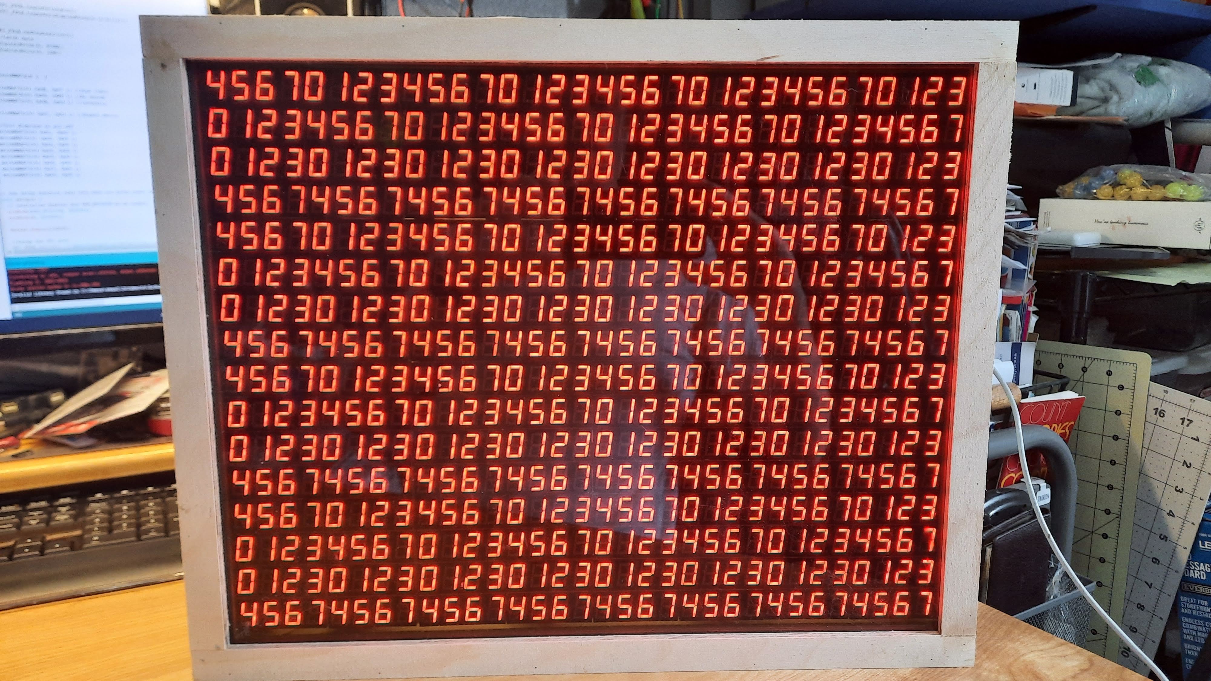
A matrix built from sixteen boards each containing eight - four character seven segment displays for a total of 4096 individual segments.

Similar projects worth following
After seeing things like the DigitGrid and the Pligboot Matrix I decided that I was going to build a 7 segment LED matrix to add to my collection of LED clocks and displays.

After seeing things like the DigitGrid and the Pligboot Matrix I decided that I was going to build a 7 segment LED matrix to add to my collection of LED clocks and displays.

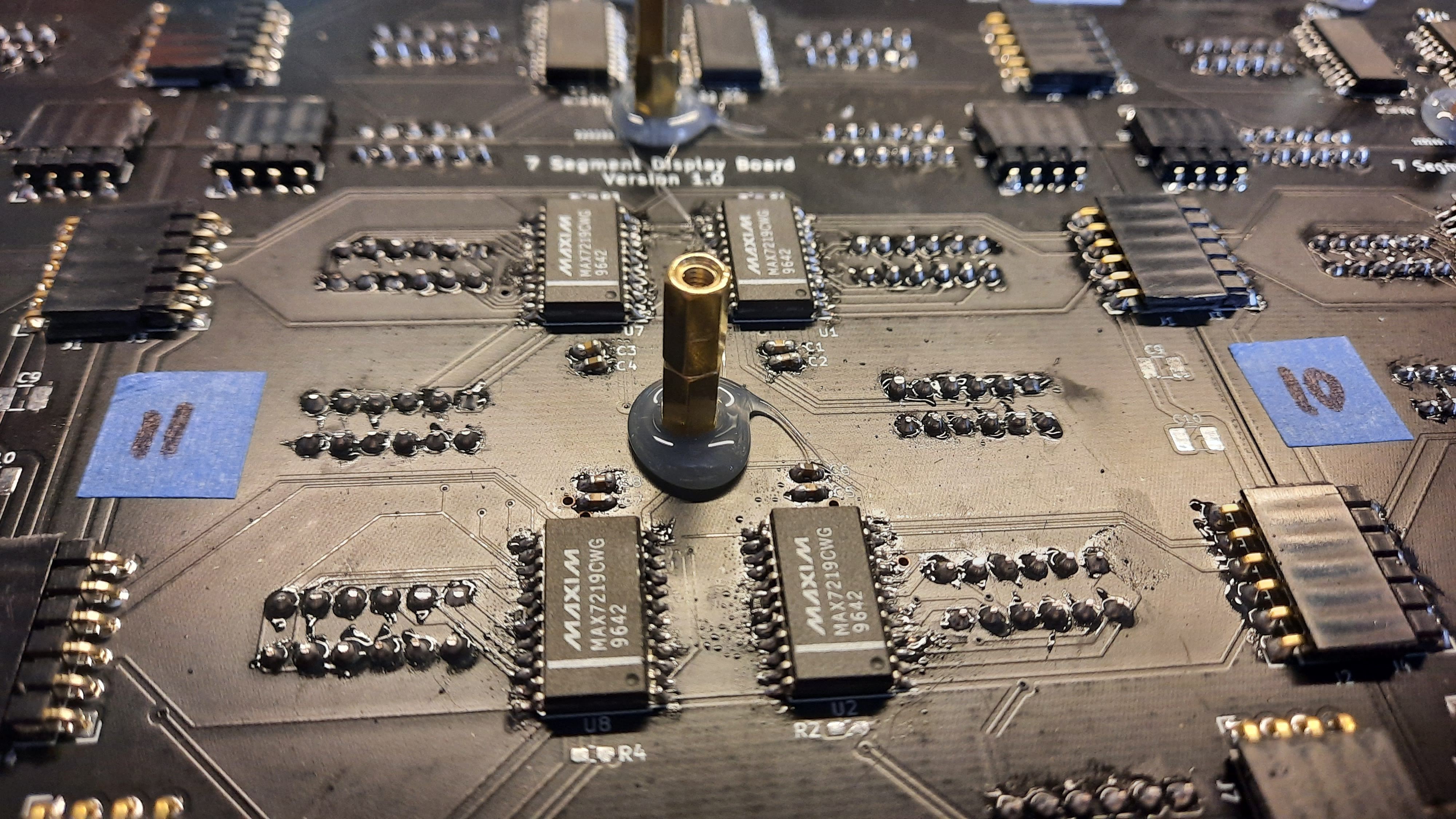
First off was deciding how big I wanted to go.  I decided on a nice round 512 seven segment displays.  I did not want to have one massive board to contain everything so I broke the display board into sixteen smaller boards.

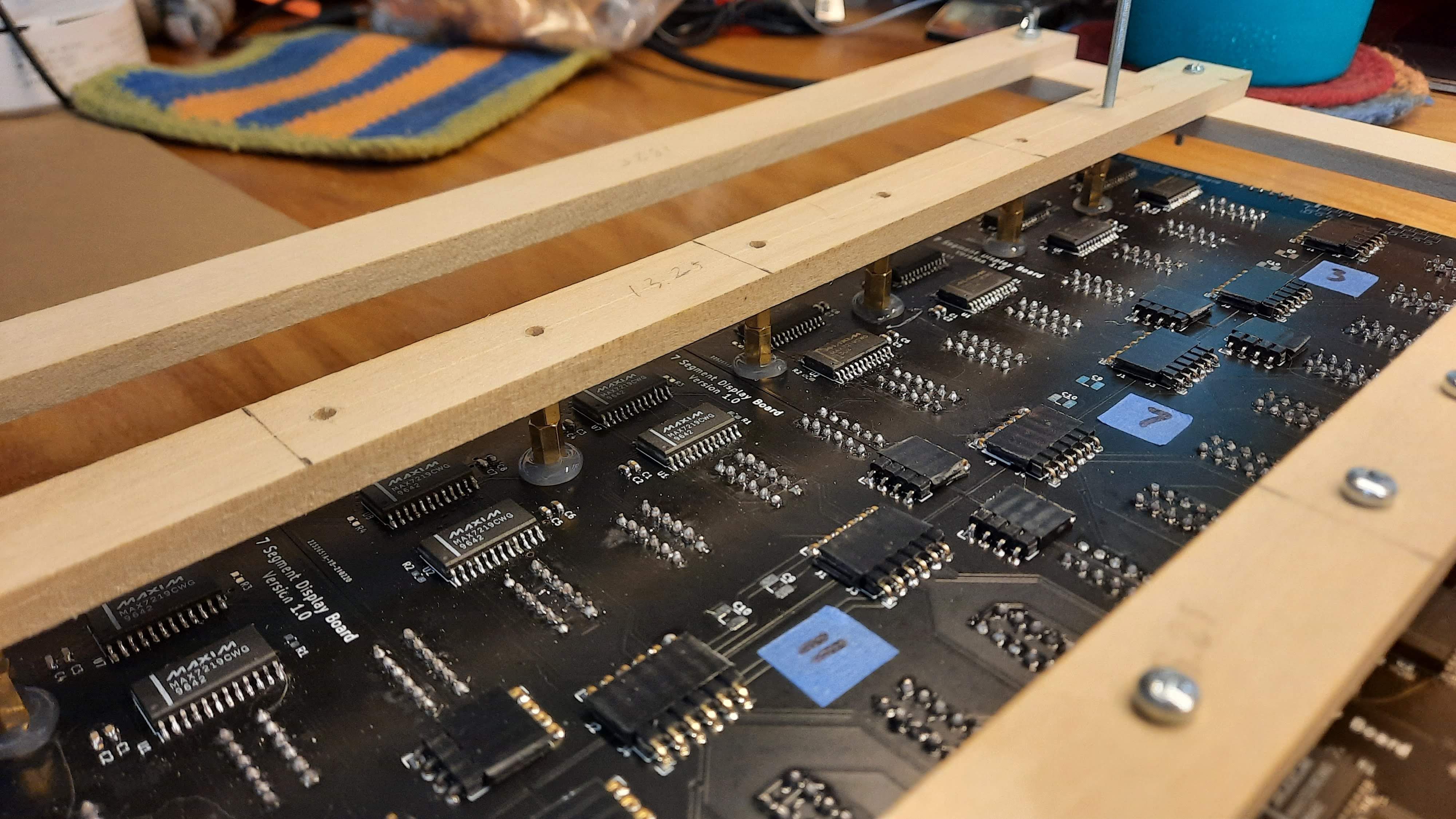
Each board will contain a four MAX7219's driving two four character 7 segment displays for a total of 32 characters per board.

I decided that driving all sixty four MAX7219's in one massive SPI chain was probably a bad idea so they have been configured in eight rows of eight controllers each.  I figured this gave a good balance between speed and not driving myself crazy with wiring.

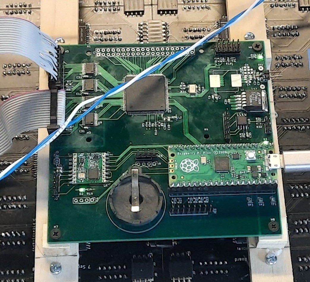
To control all of the display board I decided to go with an Intel MAX10 FPGA as I have worked with them a lot.  A Pi Pico does all of the graphics computation and feeds the data to the FPGA for mapping to the 7 segment array.  Kind of an elegant solution as the software does not have to care what it is displaying but rather just needs to know the resolution.

DisplayControllerSCH.pdf

Display Controller Schematic V0

Adobe Portable Document Format - 472.29 kB - 05/25/2021 at 14:06

Preview

DisplayBoardSCH.pdf

Display BoardSchematic V0

Adobe Portable Document Format - 278.21 kB - 05/25/2021 at 14:06

Preview

  • Finally Complete'ishly Done'ish.. just moving on to a bigger version...

    seasleyece01/30/2023 at 18:56 0 comments

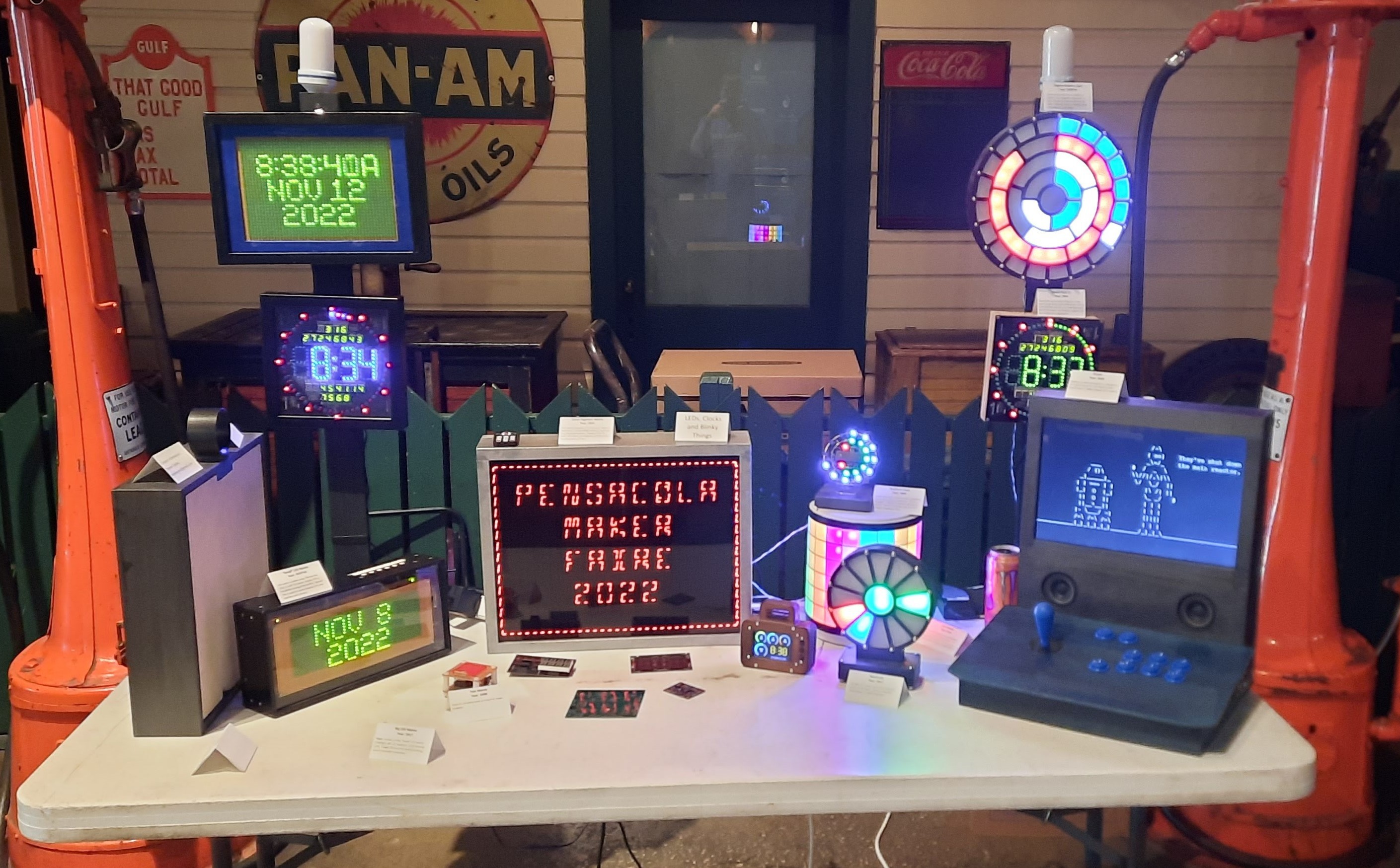
    Took the completed display to the 2022 Pensacola Maker Faire.  The reception was pretty good.

    Video of the display in action:

  • Basic Image Processing

    seasleyece06/12/2021 at 22:42 0 comments

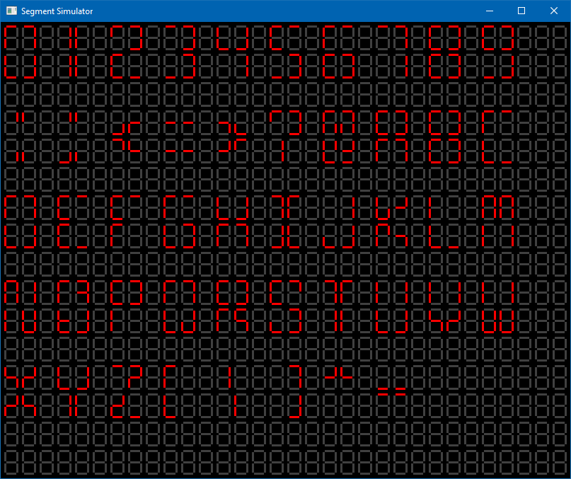
    Got basic image processing functioning and the new segment mapping scheme looks to be holding up fairly well.  Images are created as black and white BMPs then converted to C byte arrays for display.

  • Fonts, Fonts, Fonts

    seasleyece06/11/2021 at 21:43 1 comment

    I decided I needed some fonts then I got carried away and ended up with like 6-7 sizes and types... oh well.  The fancy 6x6 font is an adaption of the one seen on Here.  Not 100% sure who the originator is. 

    Font 2x2 - Covers ASCII characters 0x30 to 0x5F... Google it
    Font 2x2 - Covers ASCII characters 0x30 to 0x5F... Google it
    Font 2x3 - Covers 0-9, Colon, A and P
    Font 3x3 - Covers 0-9, Colon, A and P
    Read more »

  • Pixel Mapping - Take 2

    seasleyece06/11/2021 at 21:09 0 comments

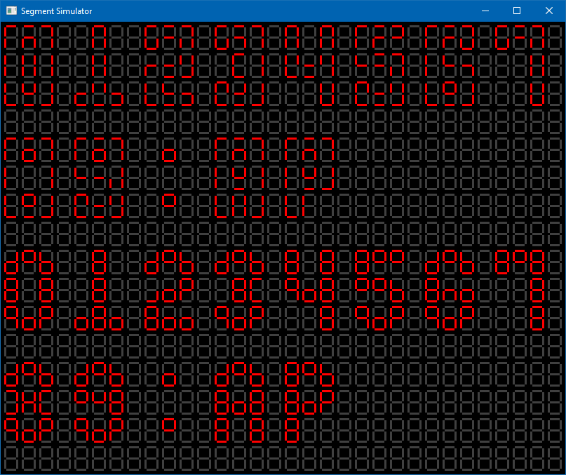
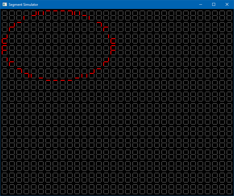
    After some thinking and a little random Googling I decided to go with the different mapping scheme that would lead to a more sparse mapping but would look better with animations.  Unfortunately this mapping yields almost 50% of the pixels not being mapped to the display.  But at least the circles are round.  Looks like I am going to have to investigate how to add a brush width to my drawing functions or just be cognizant that single pixel wide shapes may not map well.

    Pixel Mapping - Take 2
    Pixel Mapping - Take 2
     Single pixel vs double pixel wide circle.
    Single pixel vs double pixel wide circle.

  • Pixel Mapping - Take 1

    seasleyece06/11/2021 at 20:44 0 comments

    I started out using the same pixel mapping strategy as PlingBoot.  After getting some basic fonts on the screen I thought is was going to work well.  I looks fine with any graphics that are drawn with the pixel mapping in mind.  For doing any dynamic movement it does not hold up so well.

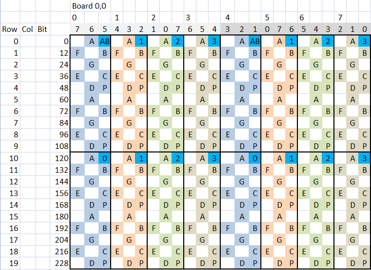
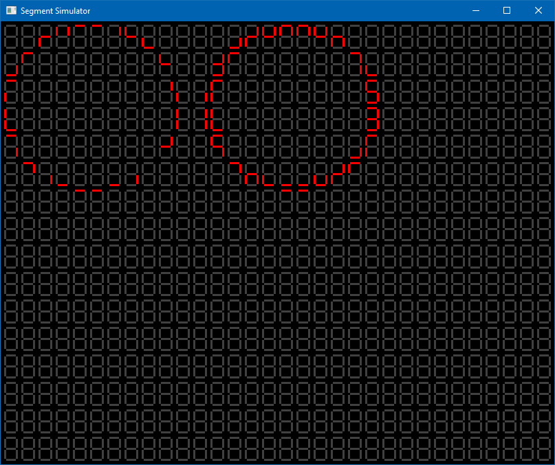
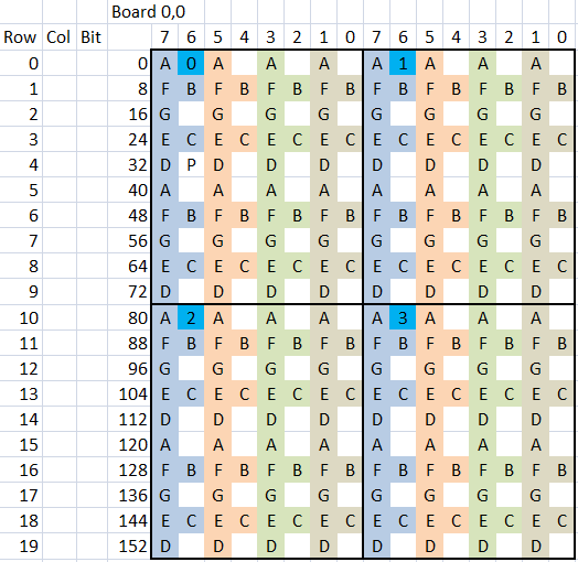
    In my base mapping attempt the array of seven segment displays are mapped from a 64x80 bit array to the segments using the method shown in the image below.  The image shows the mapping that is done fore each of the display boards.  This yields to about 30% of the pixel in the bit array not being used.  It also unfortunately yields to a none 1 to 1 mapping in the display.  This means that if you draw a circle in the bit array when it is mapped to the segment array it turns into an egg...

    Segment Mapping - Take 1
    Segment Mapping - Take 1
    That's not a circle
    That's not a circle

  • Simulation

    seasleyece06/11/2021 at 20:26 0 comments

    After getting tired of the upload process of the PICO I decided to write a simulator for the display so I could write most of the code on the PC.  The simulator started out in C# but after realizing that I did not have the knowledge to make it work correctly I switched to C++ and OpenGL.  In a previous life I have done a good bit with OpenGL but it has been 10+ year since then.

    The simulator is written using Visual Studio 2019 C++ and OpenGL.  The viewport was adjusted to yield a 2D screen.  The only difference in the code running on the PICO and the simulator is what goes on inside the display function.  In the simulator it draws the image.  On the PICO is sends the data to the FPGA for display.  Pretty happy with how the simulator came out.  It is written in such a way that it can be dynamically scaled so that when I inevitably make a bigger display I can use the same simulator.

  • Well that sucks....

    seasleyece05/24/2021 at 23:47 0 comments

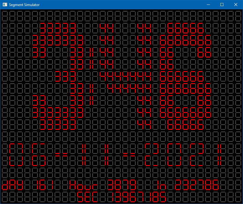
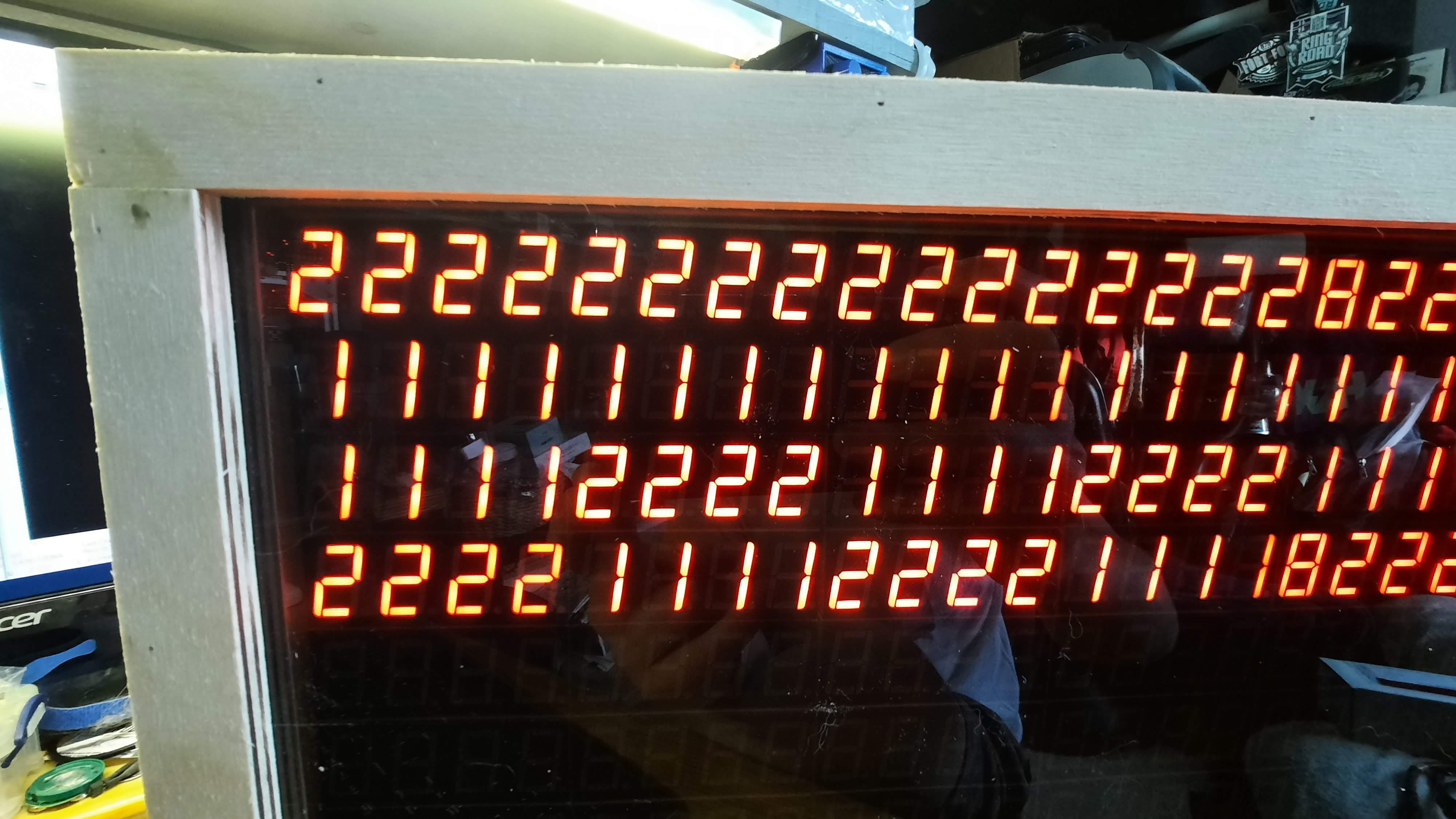
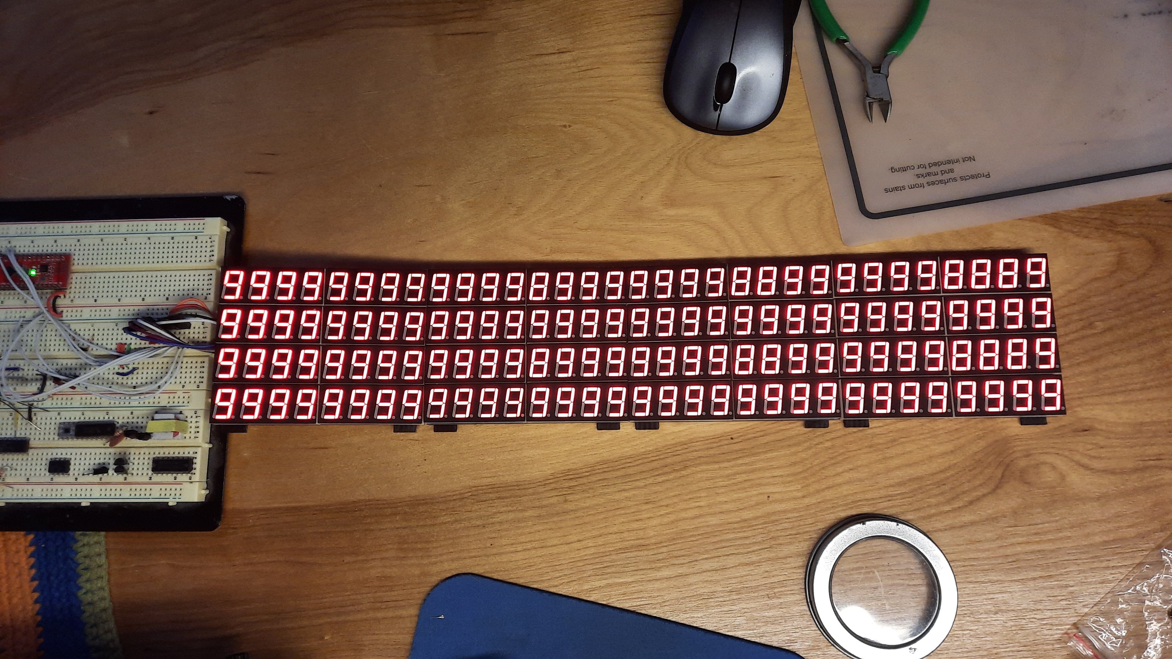
    After getting the FPGA and PICO up and running it looks like I decided to flip the orientation of two of the displays on each display board.  Fortunately I have an FPGA that is really good at single clock data remapping.  A little bit of hacking in an inversion bit to the Chip Controller module in the FPGA and everything is better.

    That is a lot of numbers......

  • Control Board Update

    seasleyece05/24/2021 at 23:42 0 comments

    Unfortunately as I was excited to the display going I did not do much to document the control board assembly.  It went fairly well.  No white wires were needed as of yet. Only oppsie so far is that the two connectors for the display chains are about .05" to close to allow two ICD connectors to plug in.  Had to create crimp connectors for the other.

    Things tested:

    • Power Supply (ditched the switcher and just used the linear regulator)
    • Pico is up and running
    • FPGA comes up and configures
    • All SPI outputs for the display matrix are working.

    Things to tested: Basically everything not required to make lights blink...

    • Real time clock.
    • Temp sensor
    • RF Module
    • ATINTY for IR receiving
    Read more »

  • Mechanical Assembly

    seasleyece05/24/2021 at 23:24 0 comments

    The box and supporting structure is made from hardware store Poplar.  A rectangular box surrounds the display boards.  The boards are held off the grid using 10mm M3 standoff because that is what you can get quickly from Amazon. The standoffs are held to the PWB using hot snot (aka hot glue).  Not the best approach but works.

  • Testing Display Boards

    seasleyece05/24/2021 at 23:20 0 comments

    After some grunting and possibly a little bit of light profanity I finally got the display boards working.  Turns out I pulled the current setting resistor on the MAX7219 to ground rather then VCC like it is supposed to be.  Fortunately the ISET pin is next to the VCC pin so no white wire is needed.  Oh well, only have to bodge 64 little freaking 0603 resistors between the pads of an SOIC.  

    To test the displays I rigged up trusty Arduino Nano to control the displays.  And the LIGHT UP!!!!

    Now to build a mount for all the displays with no screw holes....  should have thought about that more.

View all 15 project logs

Enjoy this project?

Share

Discussions

Spencer Maroukis wrote 05/12/2024 at 23:09 point

Love these 7-seg display projects, I'm working on my own too. Did you make that simulator software and do you have an executable you can share? I'm trying to figure out my pixel mapping before I get my hardware.

  Are you sure? yes | no

dearuserhron wrote 06/12/2021 at 12:15 point

Writing your own font viewer is a right way to go. I have to code my own once I get to prepare fonts for my #Coolsystem  .

  Are you sure? yes | no

Dan Maloney wrote 05/24/2021 at 19:58 point

Oh, man -- can't wait to see this all lit up!

  Are you sure? yes | no

Similar Projects

Does this project spark your interest?

Become a member to follow this project and never miss any updates