 seasleyece
After some grunting and possibly a little bit of light profanity I finally got the display boards working. Turns out I pulled the current setting resistor on the MAX7219 to ground rather then VCC like it is supposed to be. Fortunately the ISET pin is next to the VCC pin so no white wire is needed. Oh well, only have to bodge 64 little freaking 0603 resistors between the pads of an SOIC.
To test the displays I rigged up trusty Arduino Nano to control the displays. And the LIGHT UP!!!!
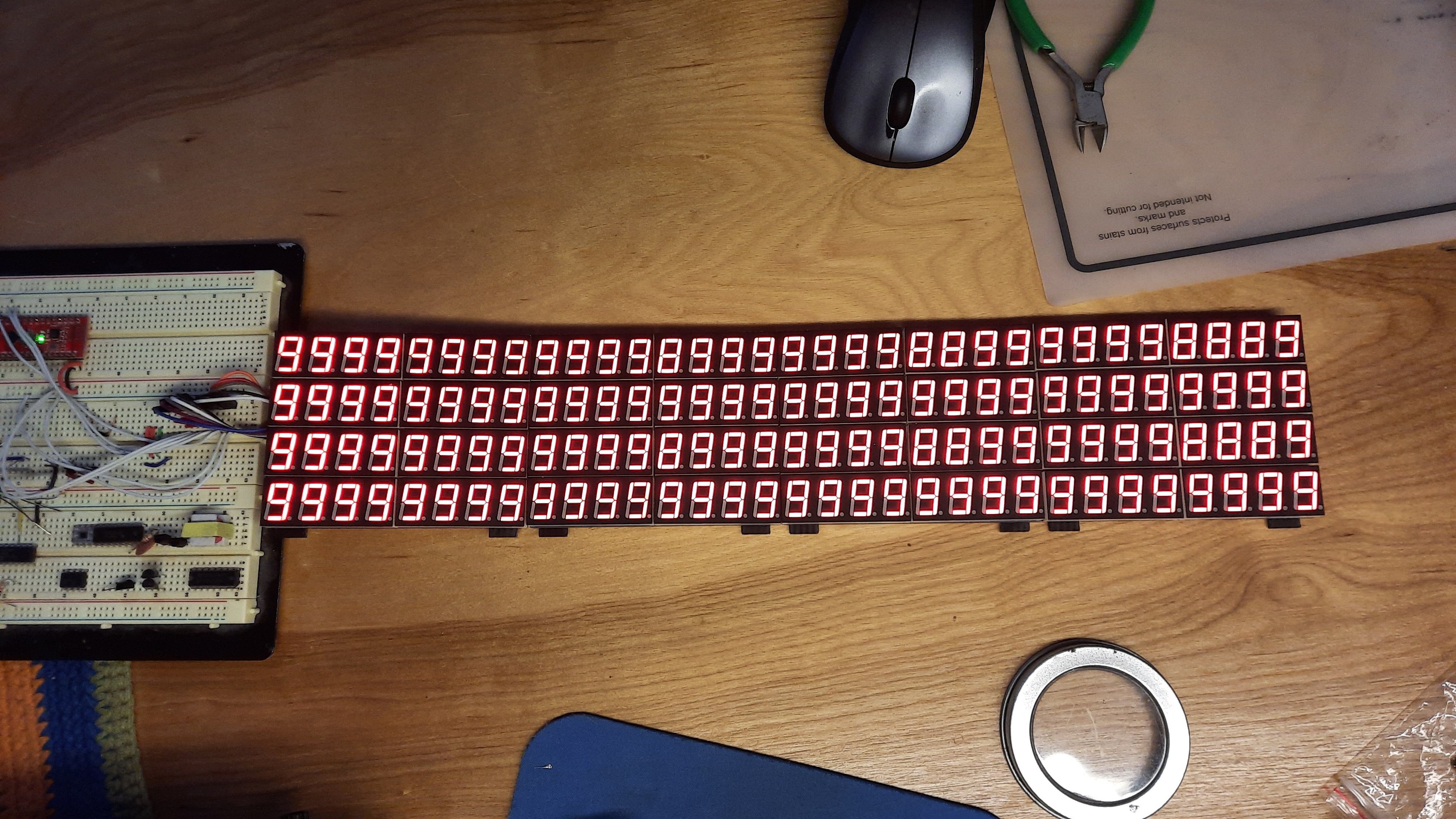
Now to build a mount for all the displays with no screw holes.... should have thought about that more.
Discussions
Become a Hackaday.io Member
Create an account to leave a comment. Already have an account? Log In.