NeoPixel timing
NeoPixels use a self-clocking signal along a single wire to serially send “1” and “0” bits, in the timing format below (from the Adafruit website.)
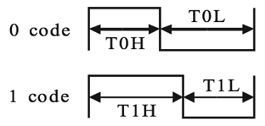

The RES signal is also known as Data Latch.
NeoPill function
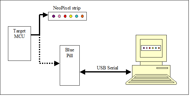
NeoPill converts the NeoPixel serial data into bytes and sends those bytes to a PC over USB. However, NeoPixel data is always written as a frame, where all the LEDs in a string are written, followed by a short pause called Data Latch. When the code running on the PC is ready for pixel data it expects to be synced with a frame. Once synced, the pixel data streams out and there is no other syncing involved.
If the target sends a partial frame then the NeoPill will definitely lose sync. This may occur during a code update or reset of the target. See the “python code” section on sync recovery.
The PC can send a few simple text messages to NeoPill to cause a resync, and one message to alter the Neopixel serial timing if required to support other addressable LEDs.
NeoPill Block Diagram
NeoPill Uses the following STM32 components:
- timers TIM2,3,4,
- serial peripheral interface SPI2,
- direct memory access DMA,
- USB interface, 72MHz system clock configuration with 48MHz USB clocking (not shown.)
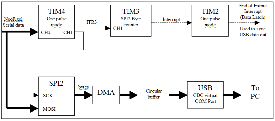
TIM4 derives the SPI2 clock (SCK) by generating a delayed pulse of 550ns after the start of either T0H or T1H, thus clocking in either a 0 or 1 bit into SPI2. SPI2 converts the NeoPixel serial data into bytes, storing them via DMA into a circular buffer. The main loop sends these bytes out the USB port to the PC. The USB interface is provided by CubeMX middleware.
An easy way to detect the Data Latch signal is to use the incoming serial data to retrigger a One Pulse Mode timer, which unfortunately is not available in the STM32F103 series. Or use a 555 timer chip. :)
A solution to detect Data Latch uses TIM3 to count NeoPixel serial data pulses and every 8 counts (or every byte received) generate a software interrupt to restart TIM2 One Pulse Mode timer (with delay). When a frame of pixel data is complete there is a pause for Data Latch. This pause is typically greater than 50us. TIM2 generates an interrupt after this 50us delay. This TIM2 End of Frame signal syncs the pixel data when the python code requests.
 Randy Elwin




 Justin R.
 Yeser Morales
 David
David
The hardest part of all this was just figuring out how to interface the STM32F103C8T6 with the computer.