Close
0%
0%

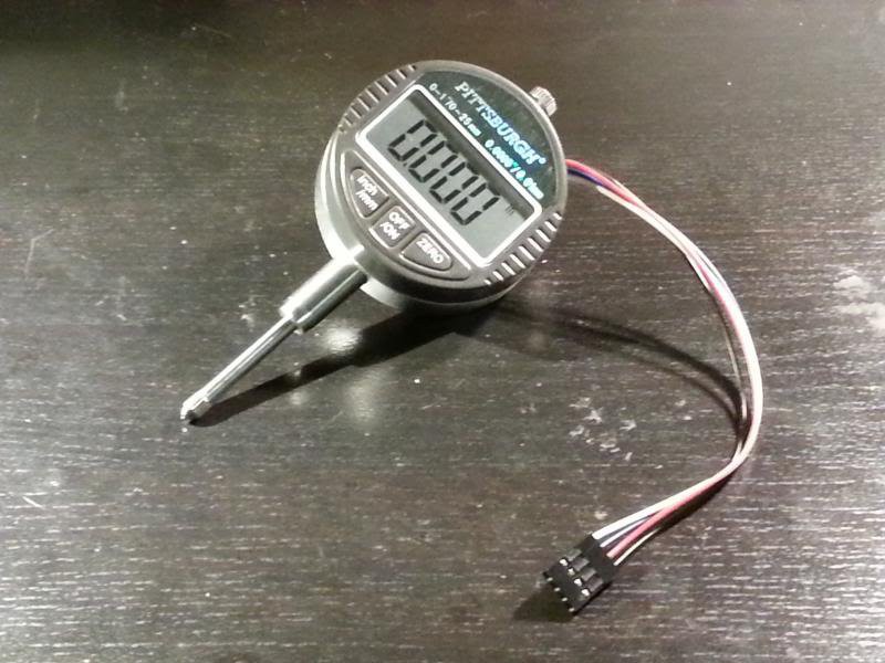
Digital Dial Indicator CNC Surface Probe

Using a cheap digital dial indicator interfaced with CNC machine to map 2D surface. Progress: Almost Done

Similar projects worth following
This project will consist of extracting data from a cheap digital dial indicator that will be mounted to my CNC router and then using that data to map a surface to correct for material that is not completely flat or parallel to the machine axes. This is most useful for engraving or routing circuit boards as the depth of cut is very critical and can change quite a bit if the surface is not perfectly flat.

Problem: When using my CNC router to engrave or route circuit boards, I always tend to run in to problems with the work piece not being completely flat or parallel with machine axes. This leads to changes in the depth of cut which are typically quite shallow for these operations. This causes the copper layer to not be cut all the way through for circuit boards, or if engraving plastic, will cause the plastic to melt if the depth of cut increases too much.        Solution: Buy a digital dial indicator from Harbor Freight, extract data from data port on the indicator, pass this data to the computer controlling the CNC router.  With the indicator mounted to the CNC machine, it will probe the height of the material to be cut in a grid pattern. With that, the surface with its imperfections will be mapped. The G-Code can then be corrected for the imperfect surface and the CNC should be able to maintain the correct depth of cut.

  • Using the Data (Part 1)

    Justin R.08/10/2014 at 03:27 0 comments

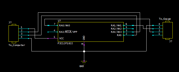
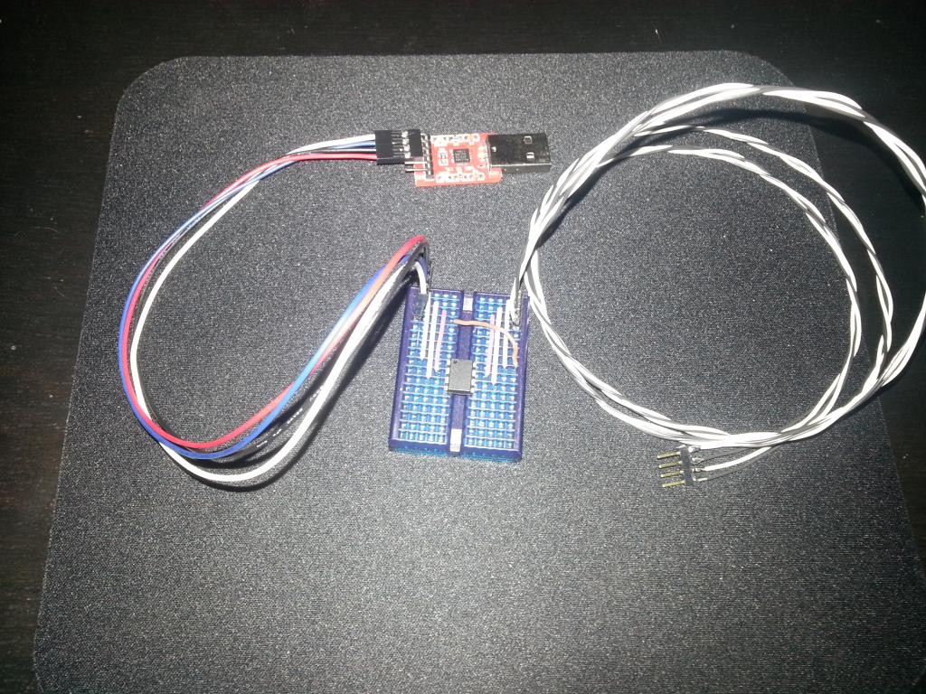
    Here is the very simple circuit I am using for the PIC chip which converts unique protocol from the dial indicator to regular UART signals that can be read by a USB TTL adapter (serial protocol @ 5V).

    This will probably the first circuit I try making once I get to that point. For now I'm just using small breadboard.

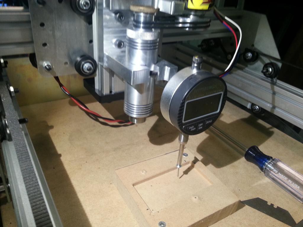
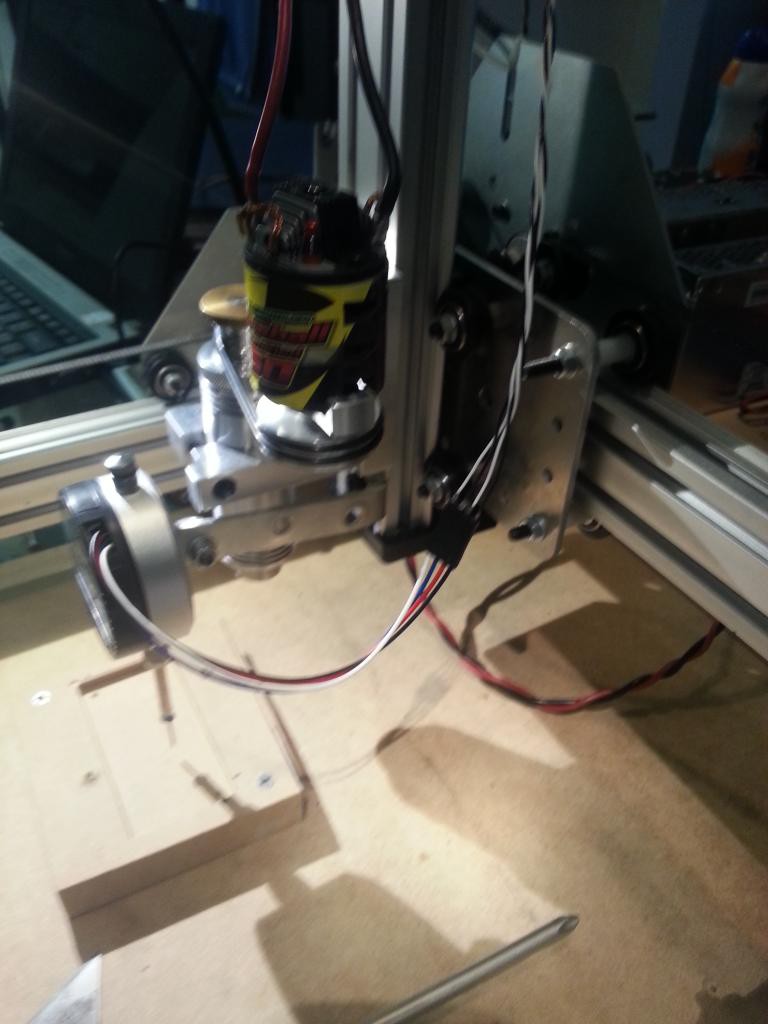
    I have also mounted the dial indicator to the CNC machine.

    Now that the dial indicator is mounted and we can read in its values from the computer, its time to make a program to use the data. Eventually this program will take in this data, create a surface map and then alter a g-code file by offsetting the Z values to match the interpolated surface map. But for a first step, I have made a program in python that will probe around in a grid and generate a surface and then displays that surface map on the screen, updating it for each point. The interpolation and altering the g-code will be added in the future. I'll post all the code once it is more or less finalized.

    Here's a video program and probe in action:

  • Interfacing Dial Indicator to Computer (using PIC Chip)

    Justin R.04/16/2014 at 03:04 6 comments

    To convert the low voltage (~1.3V) custom protocol output by the dial indicator to something that will be readable by the computer I have chosen to use a PIC microcontroller. Specifically, I will be using a PIC12F1822 because it's cheap, small, well featured, and most importantly what I have on hand currently. I will be writing the code for the PIC chip in C using mikroC as a compiler.

    Goals for this interface:

    • Read in data from dial indicator
    • Process data
    • Send data to computer (via UART)

    Chip pinout and the functions I've chosen to use for each pin:


    Reading Data from the Dial Indicator

    Since the data coming out of the dial indicator only has a voltage of about 1.3V, and I will powering the PIC chip with 5V, I can not simply read the data and clock lines using standard digital I/O reads (FALSE will always be returned since the voltage never gets high enough to trip the TRUE threshold).

    Originally I thought I was going to have to use a hardware level converter using a transistor and pull-up resistor, but I have since realized that I can read the data as analog and make my own threshold HIGH and LOW in the software. I was originally concerned that the analog read would be too slow depending on how fast the data coming from the dial indicator is clocked. But it has turned out that it is plenty fast to reliably read the data and clock signals from the dial indicator.

    Here is the process for reading the data:

    1.  Wait for the Clock line to go LOW (it's natural state is to stay HIGH)

    2.  Repeat 24 times (to read in all the bits of the message):

    a.  Wait for a rising edge on the Clock line (LOW to HIGH transition)

    b.  Read the Data line to get the next bit

    c.  Add bit to cumulative data for this message and shift

    3.  Process Data (to be covered further down)

    4.  Send Data (to be covered further down)

    5.  Return to step 1 to wait for next message

    Note: In case we start or become un-synchronized from the data and end up waiting for the next bit of the message which will never come, we will want to have a timeout on step 2a, such that if the rising edge does not come with in a certain amount of time, we abort the current read and jump back to step 1 to wait for the next message to re-synchronize.

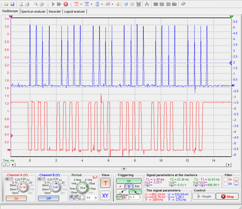
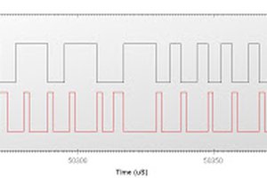
    Here is a quick screen shot showing that the PIC chip is able to successfully read the clock and reading the data signals at the correct time. The red line is the Data line from the dial indicator (keep in mind its natural state is HIGH, so this is showing all zeros except the last bit). The blue line is a temporary debug output from PIC chip showing when it detects a rising edge on the clock, and this will be where the Data line is sampled. It looks like they line up quite well.


    Processing the Data

    Once each individual bit is read in, it will need to be combined with the rest of the bits to build the final data word. This is done in a bit shifting process shown below, which is run for every bit. Keep in mind that the least significant bit is sent first so that determines the direction we need to shift.

    Process for building data word:

    1.  Take the current data bit (which will be 1 or 0) and shift it to the left 24 bits

    2.  Then add it to the data word

    3.  Shift the data word to the right 1 bit.

    4.  Repeat for next data bit

    Now that we have the data word, we can extract the measurement portion of it by taking bits 0-19. Taking the modulus of this number and 2 will give the last digit (which can only be 0 or 5, 0="0" and 1="5".  Then divide by 2 and this will leave the rest of the digits in decimal form. They can be converted to ASCII characters by breaking them up in to their individual digits then adding 0x30.


    Sending the data

    The data will be sent to the computer using the built-in hardware UART in the PIC chip.  So all that is required is setting up the UART and loading the send register with each character to be sent one at a time. 

    The PIC chip UART was configured...

    Read more »

  • The Digital Dial Indicator and How to Read From It

    Justin R.03/17/2014 at 02:14 3 comments

    I purchased the digital dial indicator from Harbor Freight (Item # 93295) for $29. Now normally I don't have particularly high expectations for products from Harbor Freight, but I have to say that I'm actually quite impressed by the quality of this indicator. Even the box it came in was made from thicker cardboard and had a nice design. The indicator itself is made from more metal than plastic (only the front part of the case and buttons are plastic). The buttons have real microswitches behind them and have a nice solid feel.

    But the real reason I got this indicator was in the hopes I would be able to extract/export the data and send it over to a computer. Now I knew other cheap chinese calipers tend to have a data port that other people have successfully been able read data out of, so I was hoping this would have a similar port even though it is not a caliper.

    The first thing I noticed after buying it was there were two covers on the top of the indicator. One of them held the battery and the other one happened to have the magic data port I was looking for, Yay!

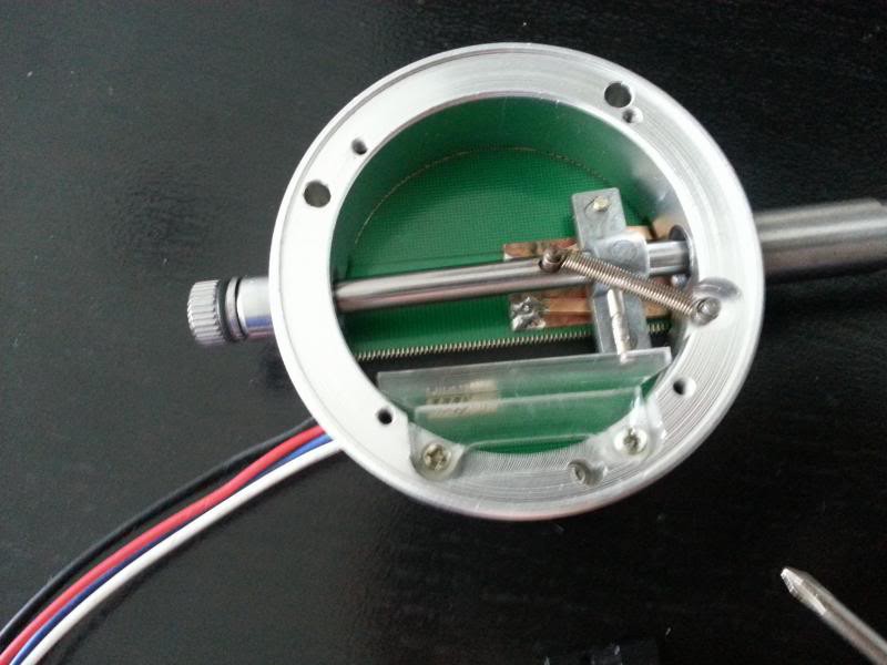
    Unfortunately I didn't take any pictures before proceeding to tear it completely apart, but I have the next best thing, pictures of it going back together:

    Exploded View:

    Exploded View (everything flipped over):

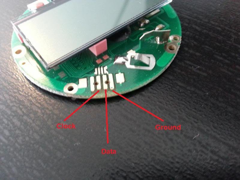
    After some quick testing I found this was the pinout I wanted from the data port:

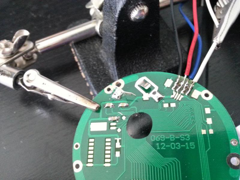
    Soldering the wires on to the pads of the data port:

    After getting everything put back together, I tried to test it out by connecting it to the logic analyzer part of my USB oscilloscope. I couldn't get any reading to show up and it turns out that the voltage levels of the clock and data line are just too low to be picked up by the logic analyzer (1.3 V = High).  So I ended up having to use the 2-ch oscilloscope function to take a look at the data.

    Here is the reference I used on how to interpret the data being output by the indicator: http://www.yuriystoys.com/2013/07/chinese-caliper-data-format.html

    Data is output in six 4-bit nibbles. The first five sent represent the measurement in binary scaled by 2000 counts per inch (when in inch mode). The final nibble is a status word that indicates whether the measurement is positive or negative and also whether it is in inches or millimeters.

    Proof of Concept Test:

    Setting the indicator to an arbitrary distance, I tried to interpret the data to get a measurement that matched the display.

    Keep in mind that the measurement value is sent LSB first, MSB last (so its basically backwards in the above image, at least for the way I'm used to seeing numbers).  111111100 converts to 508 decimal and after dividing by 2000 counts/inch, it gives us 0.254 which matches the display! So now we know how to make sense of what is coming out of the indicator's data port.

    Next Step:

    I need to figure out the best way of importing this data to the computer controlling the CNC router. Right now, I think it is to use a PIC chip to interface with the indicator and then send the data to the computer through serial UART (with a USB adapter on the computer side). I'll also have to come up with some circuitry to allow the PIC to read the 1.3 V levels output by the indicator (probably just a transistor with a pull-up, since it won't matter if the signal gets inverted).

View all 3 project logs

Enjoy this project?

Share

Discussions

Anthony wrote 10/16/2024 at 20:53 point

I ordered https://www.amazon.co.uk/gp/product/B00TSYWPV6/

It is a 0.001mm/0.00005" model and it has a micro USB socket!

I wired it to an Arduino UNO and modified the scripts provided by others to add the extra resolution and inches/mm readout.

Script here: 

https://pastebin.com/etjU8vAG

P.S. How do you make links clickable?

  Are you sure? yes | no

Vinod wrote 06/27/2021 at 05:42 point

I have got this working up, but i am getting non linear data due to inductive noise in the system.

Dial didn't get reset though values received are started from zero in the middle of process. Any solution?

  Are you sure? yes | no

dimonsky wrote 05/15/2019 at 19:29 point

  Are you sure? yes | no

mahmoud.beltagy95 wrote 03/13/2019 at 00:50 point

I accidentally removed the screen of the digital indicator, i put it back in place but it doesn't work anymore, any idea on how to fix it?

  Are you sure? yes | no

megashub wrote 09/28/2018 at 05:10 point

Has anyone tried to interface the Clockwise Tools RS232 feed via their USB adapter into the Marlin CNC controller software? I'm specifically thinking that TH3D's unified firmware would be an ideal place for this to live. I'm not a coder, but I know that if TH3DUF supported a feed from this digital indicator, it would essentially make it plug-and-play out of the box for less technical users to start using too.  Firmware: https://github.com/houseofbugs/TH3D-Unified-U1.R2 and Video about the indicator and its interface: https://www.youtube.com/watch?v=6hweiqlWb2s

  Are you sure? yes | no

djkirkendall wrote 08/16/2018 at 02:43 point

I tried the PIC method on the same Indicator, and it just didn't work out for me. I wound up coding up a arduino nano to do the same thing, and it was much easier/faster/cheaper. Here's the code:

#define DataPin A1    //nano pin A1
#define ClkPin A0     //nano pin A0

//UART Speed
#define UARTBaudRate 9600

#define ADC_Threshold 160

//Data Format
#define DATA_BITS_LEN 24

unsigned short clk;
unsigned short clock_lpv=1;
unsigned long data_bit;
unsigned long data_word;
unsigned long measurement;
unsigned int timeout_counter=0;
unsigned short bit_count;
float total = 0;

//Arduino setup and main loop

//Defines for setting and clearing register bits

#ifndef cbi
#define cbi(sfr, bit) (_SFR_BYTE(sfr) &= ~_BV(bit))
#endif
#ifndef sbi
#define sbi(sfr, bit) (_SFR_BYTE(sfr) |= _BV(bit))
#endif

void setup(){
  //set ADC prescale to 16 (set ADC clock to 1MHz)
  //this gives as a sampling rate of ~77kSPS
  sbi(ADCSRA, ADPS2);
  cbi(ADCSRA, ADPS1);
  cbi(ADCSRA, ADPS0);

  Serial.begin(UARTBaudRate);
}

void loop(){
  
 //reset counters and data
    total = 0;
    bit_count=0;
    timeout_counter=0;
    data_word=0;
    data_bit=0;
    int analogReading = 0;
          
    //wait for clock to go low
    while(analogRead(ClkPin) > ADC_Threshold);
          
    //read in data
  while( bit_count <  DATA_BITS_LEN && timeout_counter < 50 ){
            clk=(analogRead(ClkPin) > ADC_Threshold);

            if(clk==1 && clock_lpv==0) {
              //read data bit
              
              data_bit=(analogRead(DataPin) > ADC_Threshold);
              //Serial.print(data_bit);
              
              //store data bit into word
              data_bit = data_bit << 24;
              data_word = data_word + data_bit ;
              data_word = data_word >> 1;

              //reset timeout counter
              timeout_counter=0;

              //increment bit counter
              bit_count++;
            }

            //increment timeout counter
            timeout_counter++;

            clock_lpv=clk;
  }
      
      //Serial.println();
      //if (timeout_counter >= 50){
        //Serial.println("timed out");
      //}

//extract measurement data from message (bits 0..19)
     measurement = data_word & 0b00000000000011111111111111111111;

     bool bit1 = data_word &    0b00000000000000000000000000000001;
     bool bit2 = (data_word &   0b00000000000000000000000000000010) >> 1;
     bool bit3 = (data_word &   0b00000000000000000000000000000100) >> 2;
     bool bit4 = (data_word &   0b00000000000000000000000000001000) >> 3;
     bool bit5 = (data_word &   0b00000000000000000000000000010000) >> 4;
     bool bit6 = (data_word &   0b00000000000000000000000000100000) >> 5;
     bool bit7 = (data_word &   0b00000000000000000000000001000000) >> 6;
     bool bit8 = (data_word &   0b00000000000000000000000010000000) >> 7;
     bool bit9 = (data_word &   0b00000000000000000000000100000000) >> 8;
     bool bit10 = (data_word &  0b00000000000000000000001000000000) >> 9;
     bool bit11 = (data_word &  0b00000000000000000000010000000000) >> 10;
     bool bit12 = (data_word &  0b00000000000000000000100000000000) >> 11;

     total += (bit1*1);
     total += (bit2*2);
     total += (bit3*4);
     total += (bit4*8);
     total += (bit5*16);
     total += (bit6*32);
     total += (bit7*64);
     total += (bit8*128);
     total += (bit9*256);
     total += (bit10*512);
     total += (bit11*1024);
     total += (bit12*2048);

     total /= 100;
     
     //Serial.print("total:");
     Serial.println(total);
     delay(100);
    

}

It works, cost under $10 to make (assuming you already have the indicator). Anyways, your tutorial really helped me and I thought I'd pay it forward.

  Are you sure? yes | no

dimonsky wrote 06/22/2019 at 16:54 point

Hi. Thank you very much for the code! I modified it in a way that it take every data, but not only between -4000...4000, and also distinguish a sign of the data.

// https://hackaday.io/project/511-digital-dial-indicator-cnc-surface-probe

#define DataPin A1    //nano pin A1
#define ClkPin A0     //nano pin A0

//UART Speed
#define UARTBaudRate 115200

#define ADC_Threshold 160

//Data Format
#define DATA_BITS_LEN 32

unsigned short clk;
unsigned short clock_lpv=1;
unsigned long data_bit;
unsigned long data_word;
float measurement;
unsigned int timeout_counter=0;
unsigned short bit_count;
float total = 0;

//Arduino setup and main loop

//Defines for setting and clearing register bits

#ifndef cbi
#define cbi(sfr, bit) (_SFR_BYTE(sfr) &= ~_BV(bit))
#endif
#ifndef sbi
#define sbi(sfr, bit) (_SFR_BYTE(sfr) |= _BV(bit))
#endif

void setup(){
  //set ADC prescale to 16 (set ADC clock to 1MHz)
  //this gives as a sampling rate of ~77kSPS
  sbi(ADCSRA, ADPS2);
  cbi(ADCSRA, ADPS1);
  cbi(ADCSRA, ADPS0);

  Serial.begin(UARTBaudRate);
}

void loop(){
  
 //reset counters and data
    total = 0;
    bit_count=0;
    timeout_counter=0;
    data_word=0;
    data_bit=0;
    int analogReading = 0;
          
    //wait for clock to go low
    while(analogRead(ClkPin) > ADC_Threshold);
          
    //read in data
  while( bit_count <  DATA_BITS_LEN && timeout_counter < 50 ){
            clk=(analogRead(ClkPin) > ADC_Threshold);

            if(clk==1 && clock_lpv==0) {
              //read data bit
              
              data_bit=(analogRead(DataPin) > ADC_Threshold);
              //Serial.print(data_bit);
              
              //store data bit into word
              data_bit = data_bit << 24;
              data_word = data_word + data_bit ;
              data_word = data_word >> 1;

              //reset timeout counter
              timeout_counter=0;

              //increment bit counter
              bit_count++;
            }

            //increment timeout counter
            timeout_counter++;

            clock_lpv=clk;
  }
      
      //Serial.println();
      //if (timeout_counter >= 50){
        //Serial.println("timed out");
      //}

    //extract measurement data from message
     measurement = data_word & 0b00000000000011111111111111111111;     
     
     if (data_word & 0b100000000000000000000)
      Serial.print("-");
     else
      Serial.print("+");
     Serial.println(measurement);    
}

  Are you sure? yes | no

mani.sabri wrote 08/09/2017 at 21:24 point

Images are gone.

  Are you sure? yes | no

james.buckle wrote 05/26/2017 at 12:30 point

Also carrying out the same task, details at 

http://www.bucklevision.co.uk/index.php/ramblings/digital-dti/

Trying to tidy it up and add some more images. 

Source code up to just spew measurements, I'll update it soon to respond on command when I've checked my USB>TTL outputs 3V and not the expected 5V.

  Are you sure? yes | no

james.buckle wrote 05/10/2017 at 12:31 point

I just picked one of these up as it looked like a good starting place for a ~100um displacement datalogger, did a quick scan to see if I could find any info on the serial link and bingo, this project popped up - a good place to get me started, cheers!

  Are you sure? yes | no

Woody wrote 09/28/2016 at 01:14 point

awesome project. How about adding this gadget into a 3d printer structure? we could map the surface of a piece, generate the g-code then send it to the cnc ...

source code? man, my fingers are nervous ...

  Are you sure? yes | no

Analog Two wrote 12/20/2014 at 04:05 point
I am working on an MSP430 version and notice only the lower 12 bits sent over the data line actually toggle. Did you see the same thing?
DUH 2000 counts per inch; 1 inch throw. I guess the same hardware is used for longer distances.

  Are you sure? yes | no

Justin R. wrote 12/20/2014 at 14:38 point
Yep, you nailed it. I'm pretty sure they use the same hardware and firmware (with a longer track) for digital calipers, which can be up to 12 inches or even longer. With the 20 bits for the measurement it could be up to just over 500 inches!

  Are you sure? yes | no

Similar Projects

Does this project spark your interest?

Become a member to follow this project and never miss any updates