 sotasystems
-
11Step 11
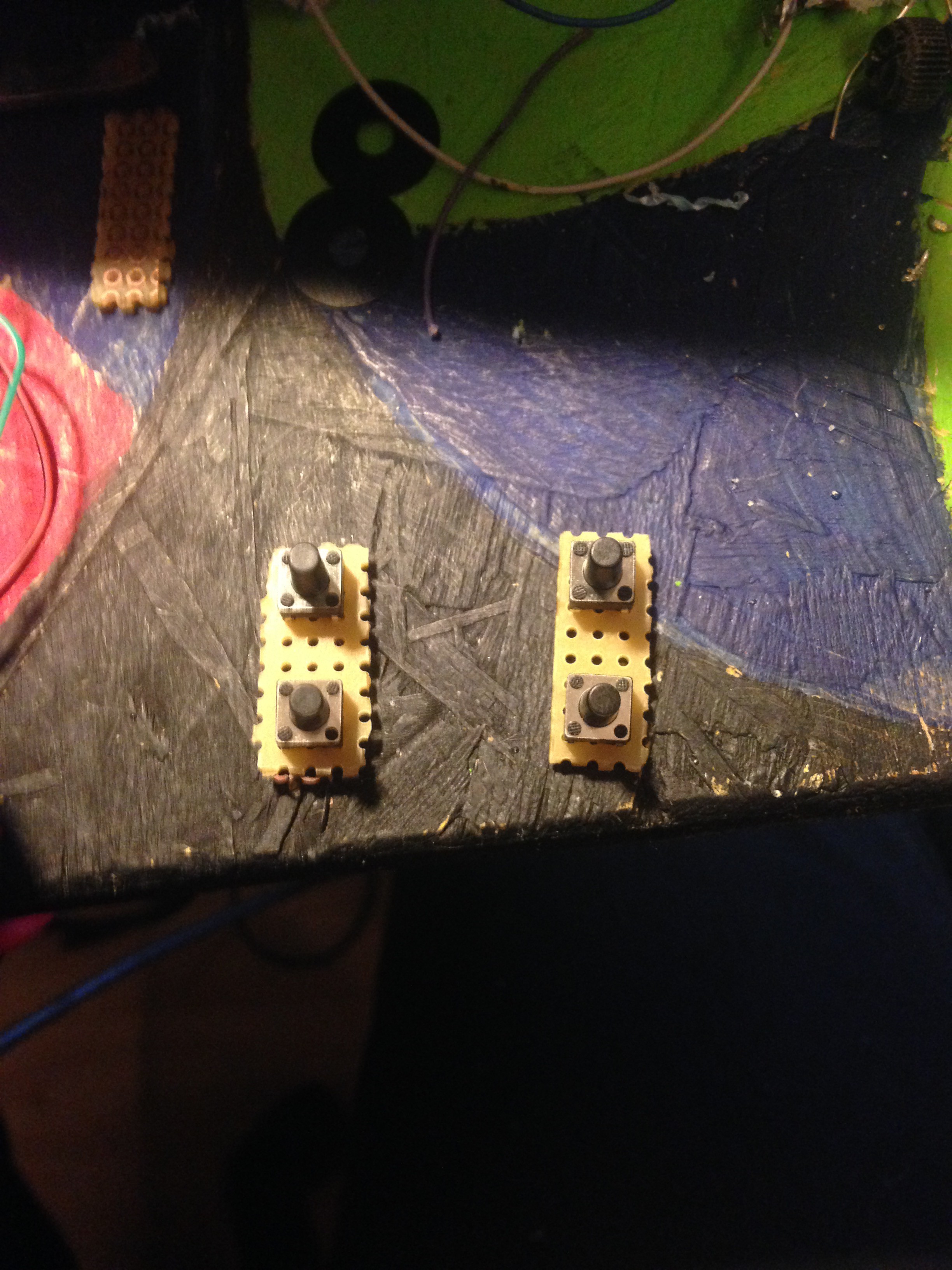
11. Adding shoulder buttons
Solder 2 tactile switches to a small piece of perfboard, and then make another one for the other side. These will be the L1, L2, R1 and R2 switches. Afterwards, drill the holes and glue them in your desired position and solder three wires from each set. Why 3? Well, you solder a wire to each switch and one wire to the pins they are supposed to be closing when pressed on. This one will go to GND. So you can solder it to GND directly. The other 4 wires you have will later be connected to your sparkfun leonardo pro micro.
![]()
![]()
-
12Step 12
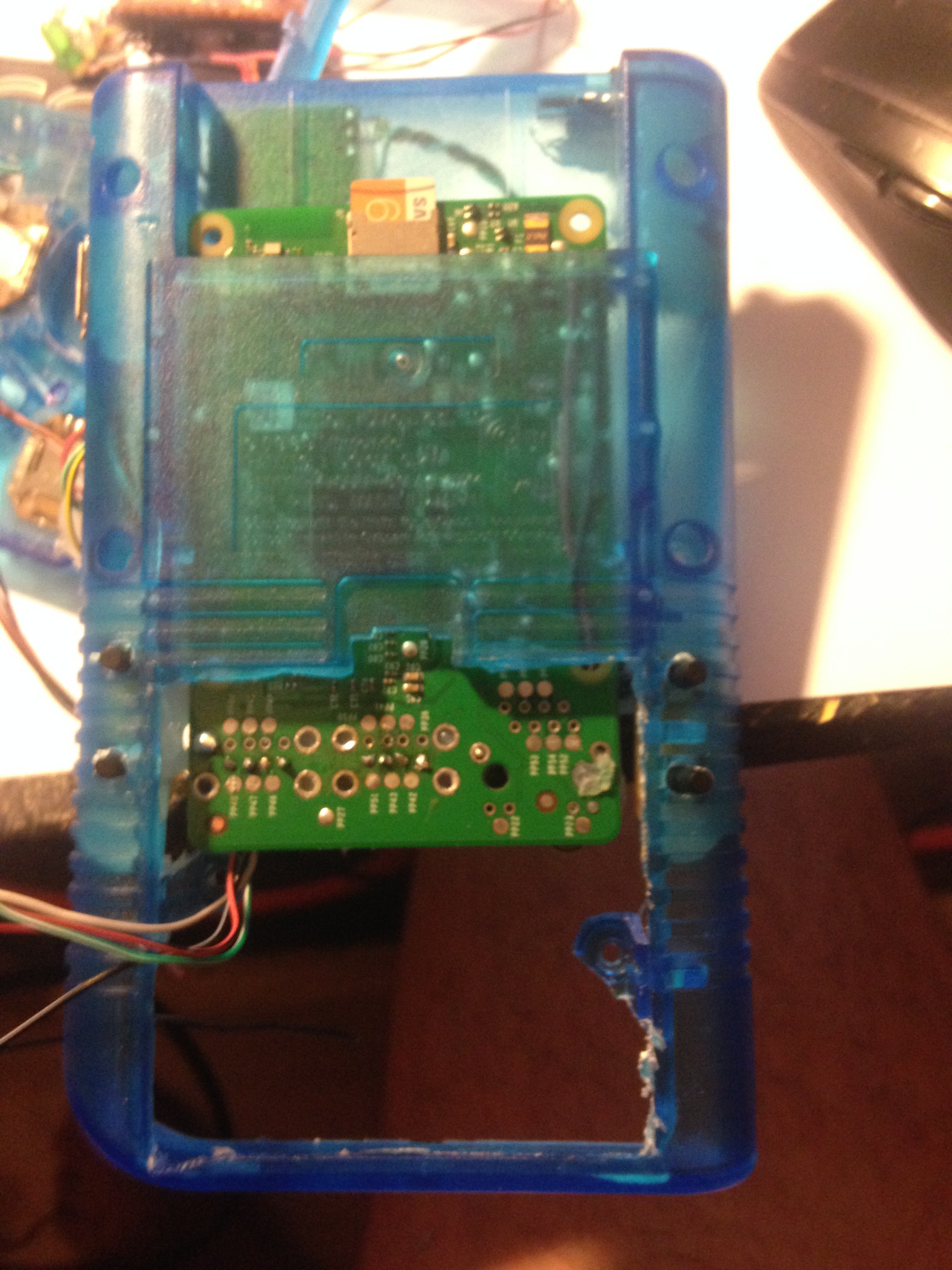
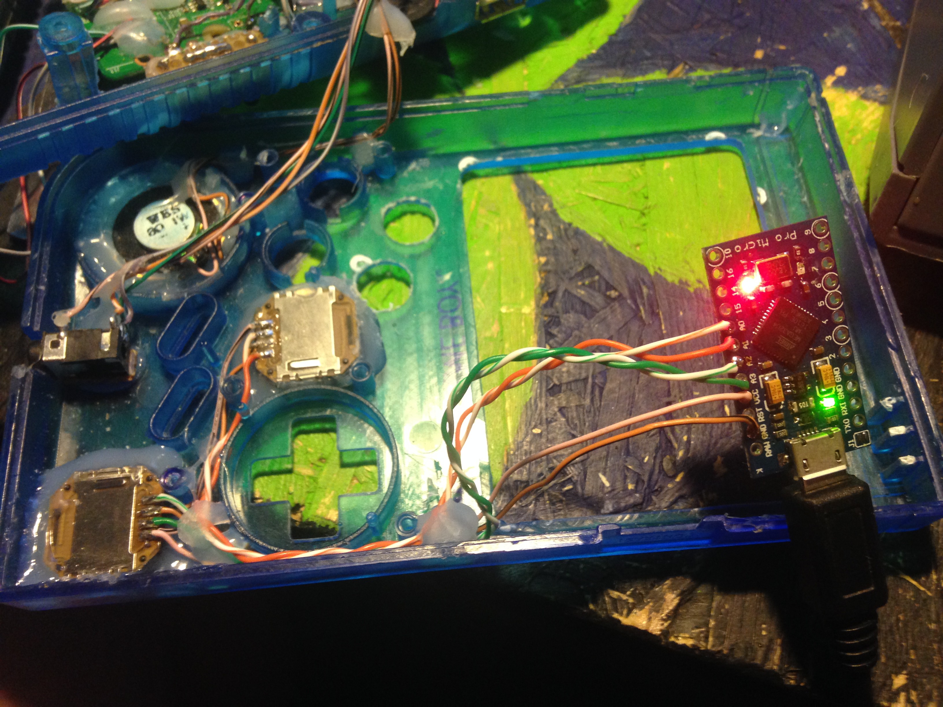
12. Gluing in the analog sticks and programming the leonardo pro micro
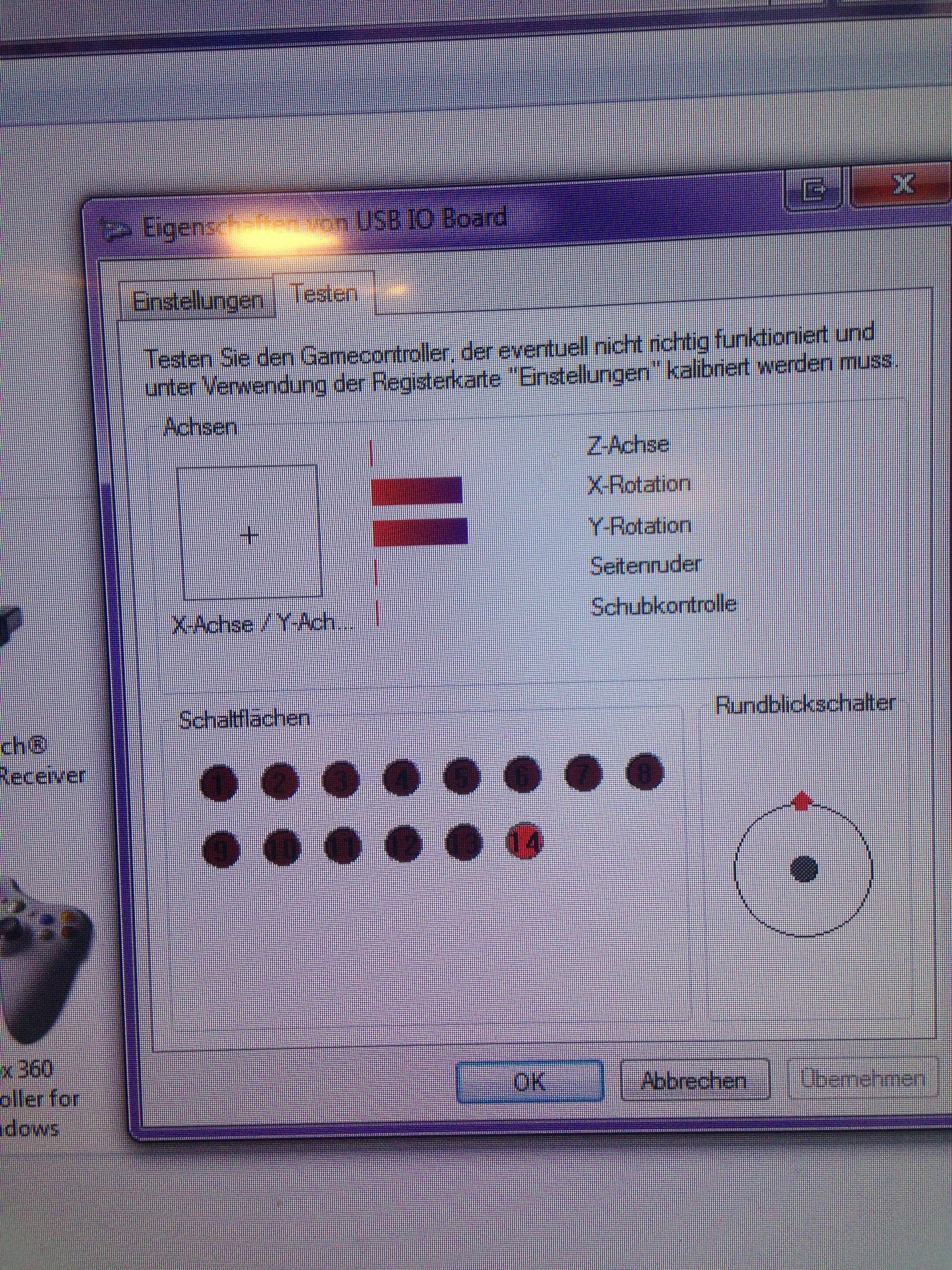
I glued in the analog sticks and soldered the corresponding wires to them. I then wrote a program to turn the leonardo into a USB joystick with 14 buttons and two analog inputs and fiddled around a little to get my code working with those analog sticks.
![]()
![]()
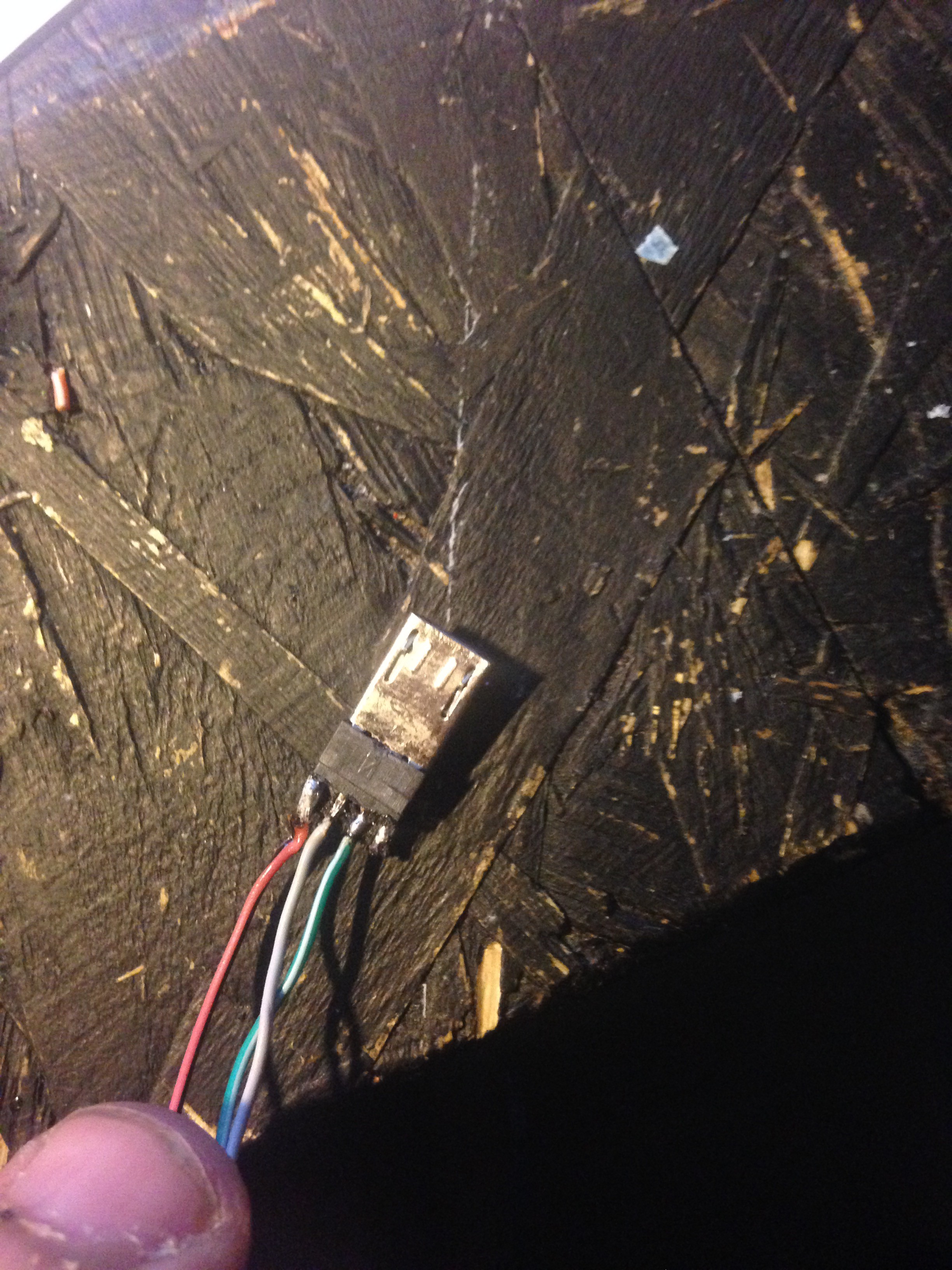
Also, to connect the pi to the leonardo later on, I took an cheap, broken µUSB cable, and got the µUSB part of it and soldered the USB wires coming from the pi to it for easy plugging in:
![]()
This original sketch is intended to be used with 2 PSP 1000 analog sticks and 14 buttons, but you don't have to connect all 14 if you don't want so many. However, if you only have one analog stick or NONE at all, you have to set "int AnalogSticks = 2;" to the number you have. E.g. 0 is no sticks at all, 1 is one stick, and 2 is 2 sticks, duh.
Also, in theory, there is a way to make it work with other 2 axis, 4 pin analog sticks, too!If you have an analog stick different from a PSP 1000 and would like to use it, I am telling you what I did to get a gamecube stick working. It may or may not work with others, though, that is why I wrote just in theory. If you still would like to try it out, please first completely follow the Normal guide below and then do the following:
Adiitional steps:
Now, when you use a different analog stick and it doesn't work correctly, the min and max values are probably incorrect. The min and max values are currently 400 and -400 without "fine tuning" for PSP 1000 analog sticks.
First, simply set "int SendReading = 0;" to 1, so it becomesint SendReading = 1;(Line 13)and upload it to the leonardo micro.
Now open the serial Monitor (Tools > Serial Monitor) and make sure the baud is set to 9600 in the lower left.
When you then move either of your analog sticks (or just 1 if you have only 1) you should see the values changing.
Then you move the stick as far left as possible (only one stick at a time, or you could get incorrect readings!), and note the displayed value and where it belongs to (X1/Y1/X2/Y2 up, down, left, right). Repeat the steps for up, down and right.
If you have all your readings, set "int SendReading = 1;" back to 0.
You then replace the numbers 400 and -400 in// Apply/"fine tune" your noted readings here: int x1Min = 400; int x1Max = -400; int y1Min = -400; int y1Max = 400; // If you only have 1 analog stick, ignore this: int x2Min = -400; int x2Max = 400; int y2Min = 400; int y2Max = -400;(Line 15-25)
with the numbers you have noted, and upload the sketch again and that should be it.Normal guide:
Now, you will need the Arduino software 1.0.5r2 for that. You can use the portable (non-install), so if you do not want to overwrite your existing Arduino IDE, you don't have to. I found that my software runs on 1.0.5r2 only, that is why you need it. And since I use 1.0.5 and 1.0.6 it didn't bother me.
https://www.arduino.cc/en/Main/OldSoftwareReleases#1.0.x
Now, when you are using an arduino clone from SparkFun like me, you need additional software. Mine does look like this:![]() If you have one that looks like this:
If you have one that looks like this:![]() I have confirmed that this one also works. Now, it might be that you have another leonardo micro clone that looks similar or actualy different from what I have used, so you have to try out yourself if it works.
I have confirmed that this one also works. Now, it might be that you have another leonardo micro clone that looks similar or actualy different from what I have used, so you have to try out yourself if it works.
The additional software you need is this:
SF32u4_boards-pre-1.6.zip (Included within this project here).
Unzip it in your Arduino/hardware folder (or your Arduino document folder alternatively) so that it would look like this on windows for example:
C:\Program Files (x86)\Arduino\hardware\SF32u4_boards-pre-1.6
Now, to make my sketch actualy work, you need to replace two files which have been modified you can download here:
USBAPI.h (Included within this project here).
and
HID.cpp (Included within this project here).
First, navigate to Arduino\hardware\arduino\cores\arduino and then MAKE A BACKUP OF "HID.cpp" AND "USBAPI.h". Also, if you decide to just rename them, keep in mind to NAME THE EXTENSION DIFFERENT FROM ".h" OR ".cpp" OR ARDUINO WILL COMPLAIN.
Then you can place the two modified files there.
Plug in your Arduino clone.
Start the Arduino IDE and from "Tools" select "Board" and then "SparkFun Pro Micro 5V/16MHz"
and then also select your COM port.![]() (Also check that it's set right by checking what it's saying in the bottom right).
(Also check that it's set right by checking what it's saying in the bottom right).
Then from "File" select "Examples" -> "01.Basics" and then "Blink".
Upload this sketch.
If it now asks you for drivers (it may or may not), you can point it to Arduino\hardware\SF32u4_boards-pre-1.6\signed_driver, the drivers are included there.
Now everything should be prepared. You can now use my sketch to turn it into a controller with 14 buttons and 2 analog sticks:
Gamecontroller.ino (Included within this project here).
Also, depending on your setup, you can remap the Analog inputs on the top of the sketch by specifying different Analog inputs if desired. You can also remap the buttons if really needed by changing digitalRead(#) with your desired number in the loop.
Also, since my Analog sticks are rotated inside my gameboy, you might want to fiddle with the map Values (currently 400/-400) to get them in the right orientation.
Also, if you're interested, in my particular case, I use these values:// Apply/"fine tune" your noted readings here: int x1Min = 400; int x1Max = -350; int y1Min = -350; int y1Max = 350; // If you only have 1 analog stick, ignore this: int x2Min = -350; int x2Max = 290; int y2Min = 350; int y2Max = -350;(Line 15-25)Also, here is how you hook them up (passed over directly from adafruit):
![]()
-
13Step 13
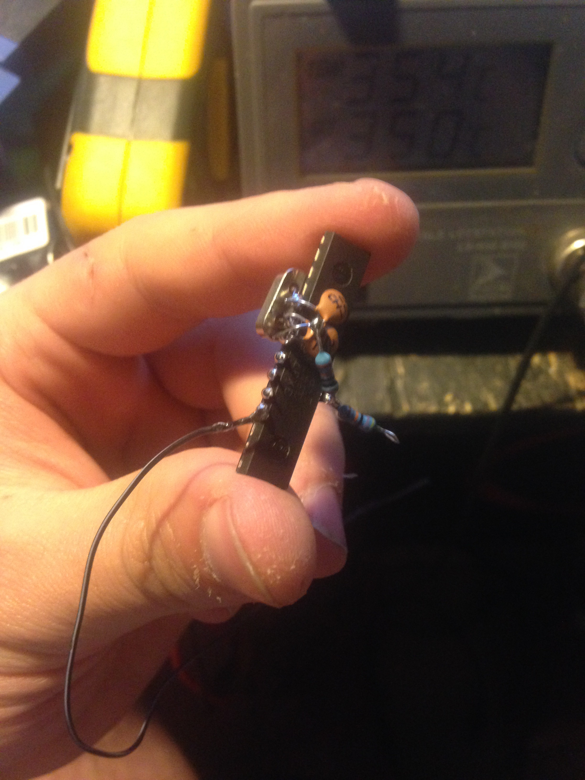
13. Adding a battery monitor with auto-shutdown
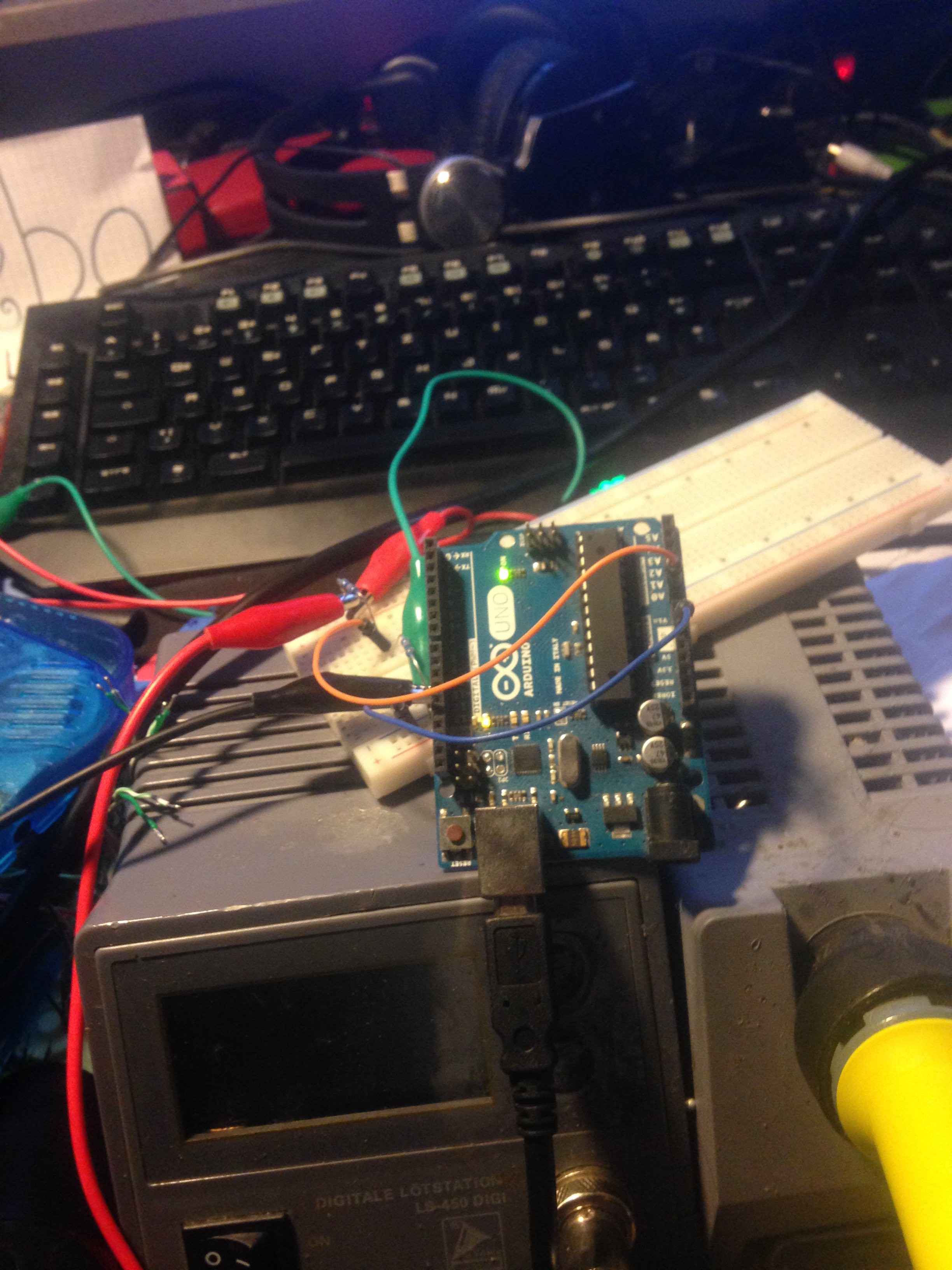
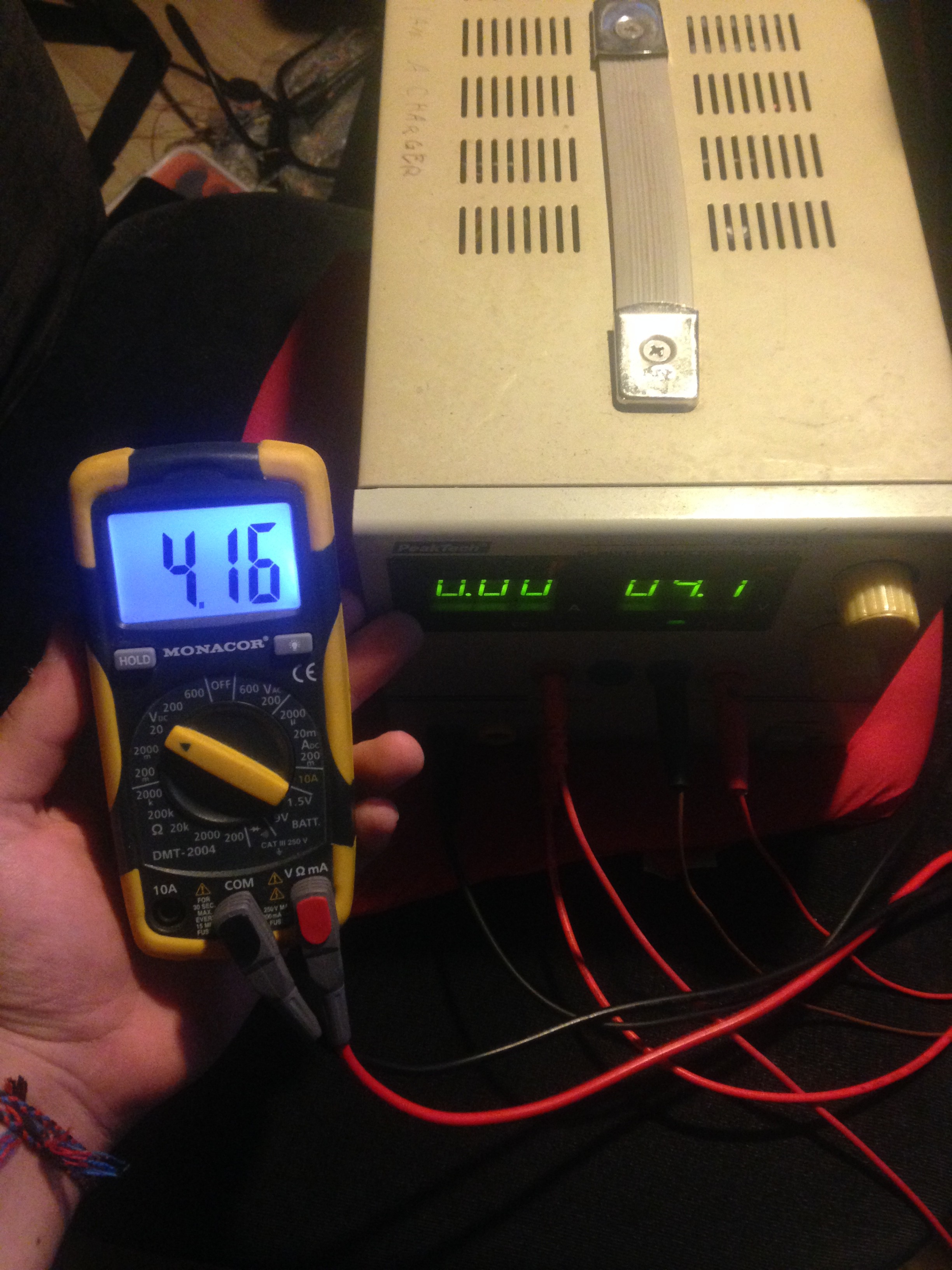
Take an Arduino UNO, and turn it into a low battery indicator as well as an automatic safe-shutdown circuit when the battery is too low. For that, connect everything on a breadboard and use a lab bench power supply to simulate a battery and get the readings I you need for best accuracy. I got my voltages by recording a video of me playing on a full battery untill my battery was totaly flat, so I could see at what minutes it is safe to shutdown and 10 minutes before that it is safe to say that the battery is almost done for.
My battery lasts for around 2 hours and 11 minutes in total.
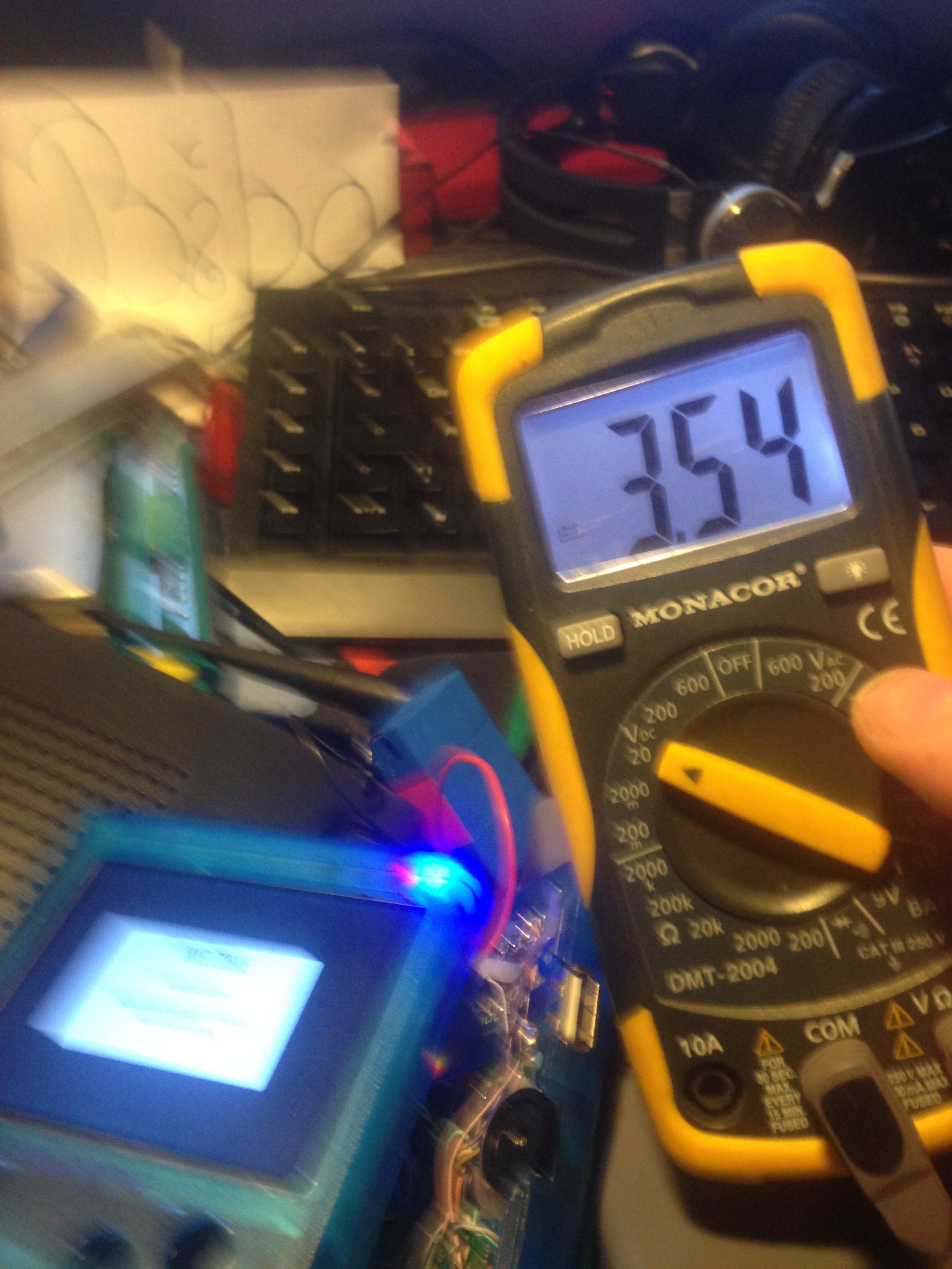
My readings are:
Battery full: ~4.16 Volt (not needed, though)
Battery low alert (red LED): ~3.54 Volt
Battery empty, need to shutdown NOW: ~3.20 Volt
(And the sketch is programmed with those readings at this moment)
You can find the sketch for this in this project labeled "batterywatcher.ino".
![]()
![]()
![]()
After everything is working, make your arduino smaller by just using the atmega as itself with a quartz, and a voltage divider as battery input and check that everything still works like that. The resistor values I used are 470k and 100k, wired up like this:
Arduino pin A0 -> 470k resistor -> Battery + :
Arduino pin A0 -> 100k resistor -> GND
![]()
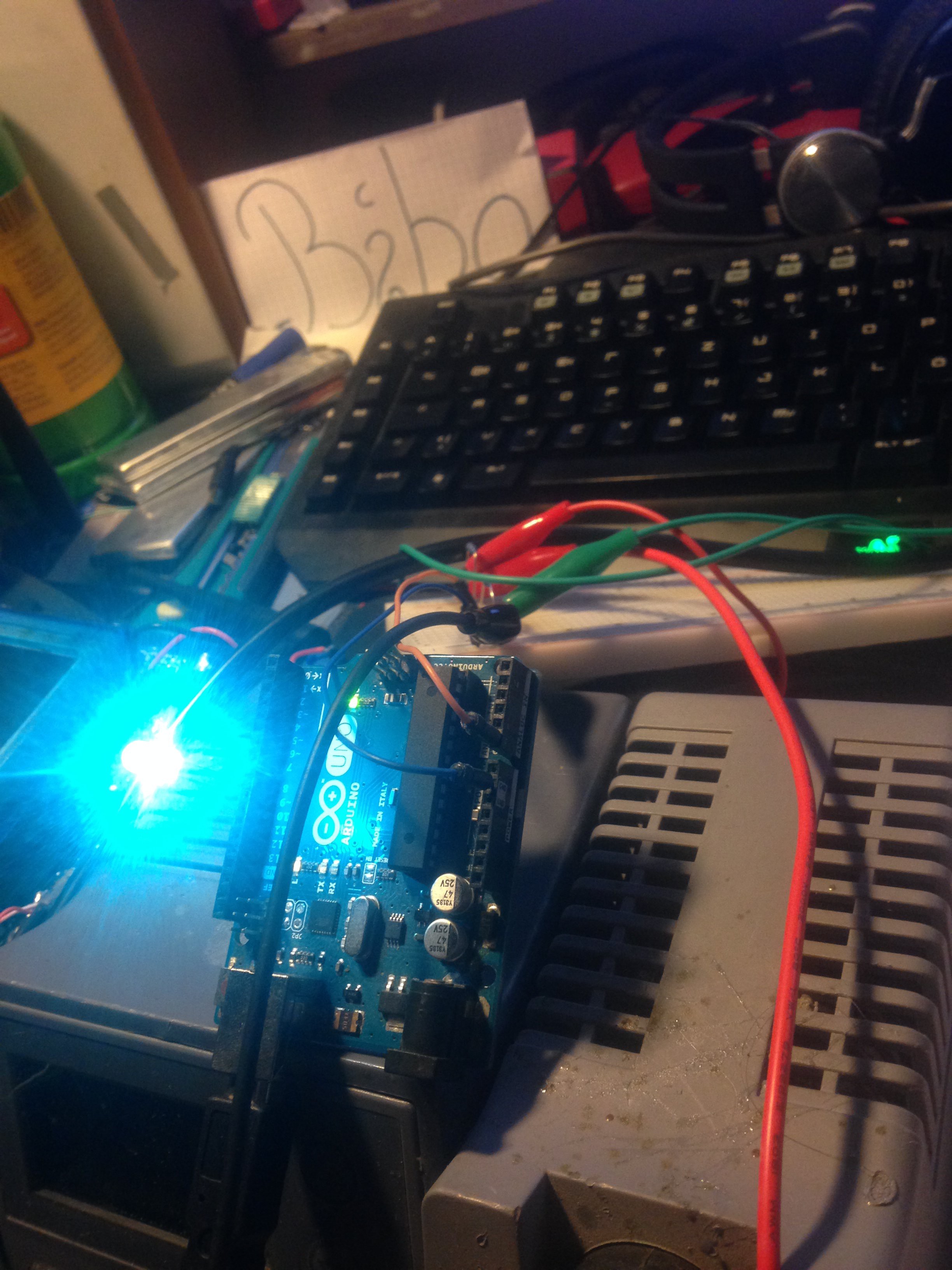
here you can see an (unfortunately) unsharp image of the low battery indicator working:
![]()
Then you solder a wire from your red LED's cathode pin to GND with an appropiate resistor, and the anode to pin 2 of the arduino. Finaly, solder a wire from your arduino's pin 3 to the center pin of the voltage divider you soldered on to your pi's GPIO. This will enable the safe-shutdown feature.
-
14Step 14
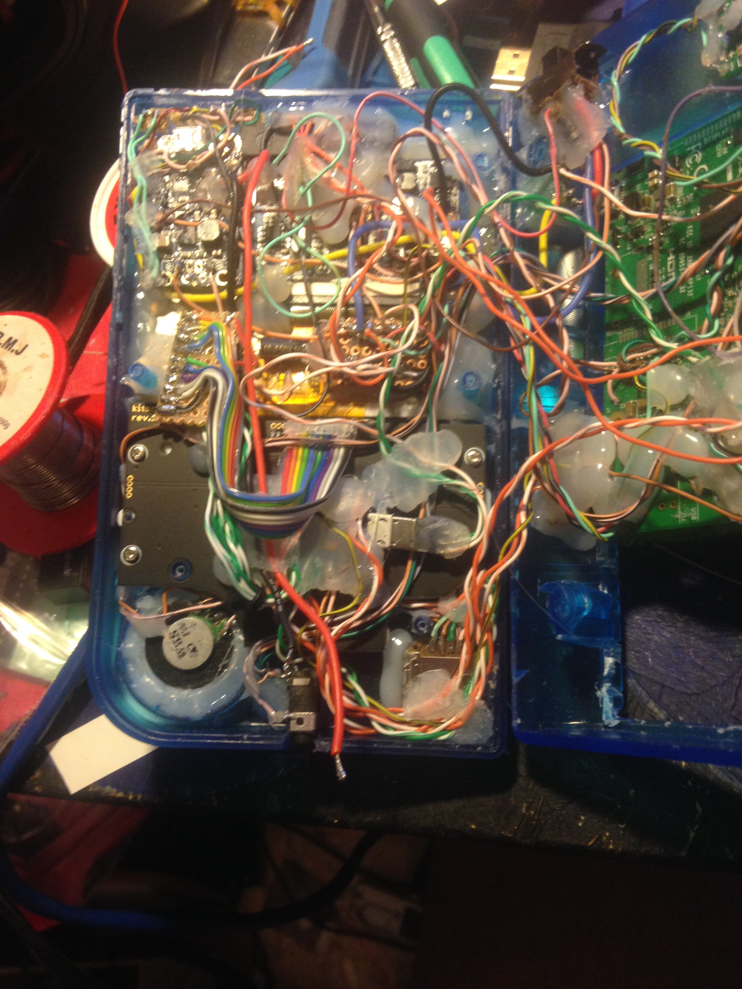
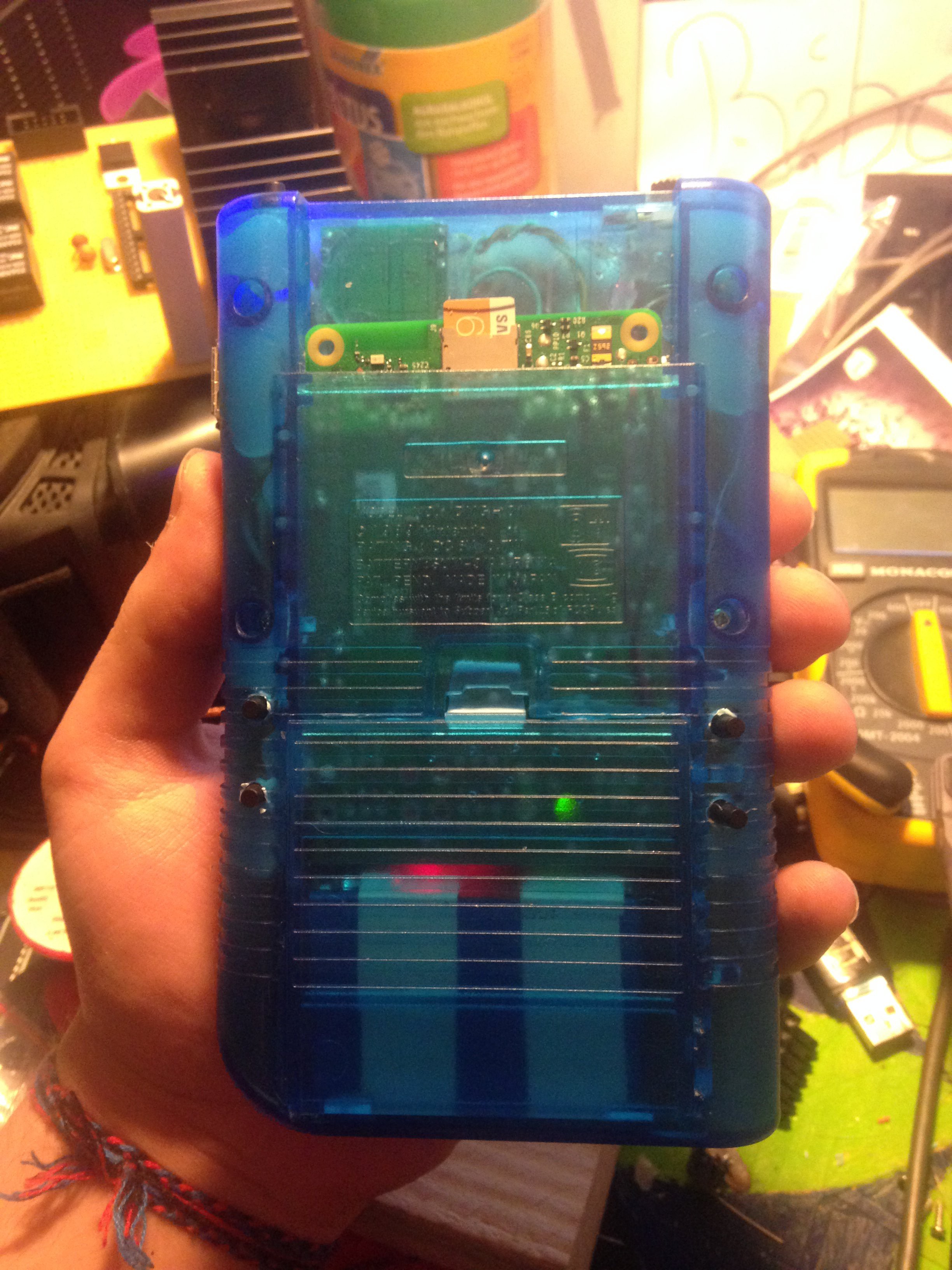
14. Adding the button PCB and the buttons
All that is left out now are the front buttons. When you have your common ground control panel, you simply solder the GND to ground (duh!) The rest of the pins are soldered to the leonardo micro's input pins, and it does actualy not really matter how you solder them on, as they can always be remapped in retropie. If you plan on using 14 buttons like I did, keep in mind to use pins RX and TX as pin 0 and pin 1 (these are configured as inputs!) As the sketch is already pre-programmed to work with buttons, no additional programming is neccessary. After that, you can close the gameboy, solder on the battery on the JST connector (or actualy use a JST cable, it's your choice) and it is finished! Now go and have fun playing! (:
![]()
![]()
![]()
![]()
-
15Step 15
15. Finishing touches
Now that your hardware is complete, getting the right settings for the display is a thing we can take care of. Note that these steps will only for this particular display that has been used in this build and may give totaly different results when using another display.
Adjusting gamelist textsize and color
First, we want to adjust the text size for the listed games a bit. For that, we do these steps:
- SSH into your gameboy
- Enter:
sudo nano /etc/emulationstation/themes/carbon/carbon.xml
- look for the phrase that contains "gamelist" (NOTE: there are 2, you need to change both.)
- in "selectedColor" (NOT TO BE CONFUSED WITH "selectorColor"!!) change the value to 3082ce. This will make the selected game's font blue instead of read, which makes it much, much better than the original red on this display.
- in fontsize, change the value to 0.05. This will make your game's list text bigger.
- close, and save (Ctrl + X).
- reboot
Overscan
Next, we want to adjust overscan. For that, we do these steps:
- SSH into your gameboy
- Enter:
sudo nano /boot/config.txt
- these are the recommended overscan settings for this display:
overscan_left=-16
overscan_right=-16
overscan_top=-24
overscan_bottom=-20
- close, and save (Ctrl + X).
- reboot
Console size
Next, we want to resize the console size so that text becomes easier to read on such a tiny screen. For that, we do these steps:
- SSH into your gameboy
- Enter:
sudo nano /boot/config.txt
- these are the recommended console settings for this display:
framebuffer_width=320
framebuffer_height=240
- close, and save (Ctrl + X).
- reboot
Adjust emulator aspect ratio for non-Nintendo 64 emulators
There are some emulators that don't use 100 % of the screen, e.g. black bars. To get rid of them, the aspect ratio needs to be set manualy. Note, that this steps will not work for the Nintendo 64 emulator, instead there is other steps for that below. Now, we do these steps:
- Load the desired roms to the gameboy and open a rom from the system.
- If you notice black bars, press the "Select" and "X" key on your gameboy simultaneously. That way, you are in the main menu of retroarch. Here you can change some settings on the fly.
- Navigate to "Settings" > "Video" > "Aspect Ratio Index" and try some settings with the left/right arrow keys. Changes will be applied immediately. If you have found a good setting, note it and remember what emulator you were using. Also, note that this value is ONLY FOR THIS PARTICULAR EMULATOR! If you have your values for each emulator you are using (except N64), do these steps:
- Close out of all emulators
- SSH into your gameboy
- Enter:
sudo ~/RetroPie-Setup/retropie_setup.sh
- Navigate to "Configuration / tools" > "configedit" > "Configure basic libretro emulator options" > The emulator you use (e.g. "gb")
- Go to "Aspect Ratio" and press enter
- Choose your aspect ratio from the list
- Repeat the steps for all other emulators.
- Escape out of it until you are back at the normal shell, and then test it out. Changes should have been applied immediately.
Adjust emulator aspect ratio for Nintendo 64 emulator
Because the Nintendo 64 emulator that is used in RetroPie (mupen64-plus) is not an 100% retroarch-compatible emulator, the above steps won't work and we need to do something else instead:
- Close out of all emulators
- SSH into your gameboy
- Enter:
sudo nano /opt/retropie/emulators/mupen64plus/bin/mupen64plus.sh
- in Line 289, there is a line that says "SDL_VIDEO_RPI_SCALE_MODE="
- change the value in there to 2. That one is good for this particular screen.
- close, and save (Ctrl + X).
- Changes should have been applied immediately.
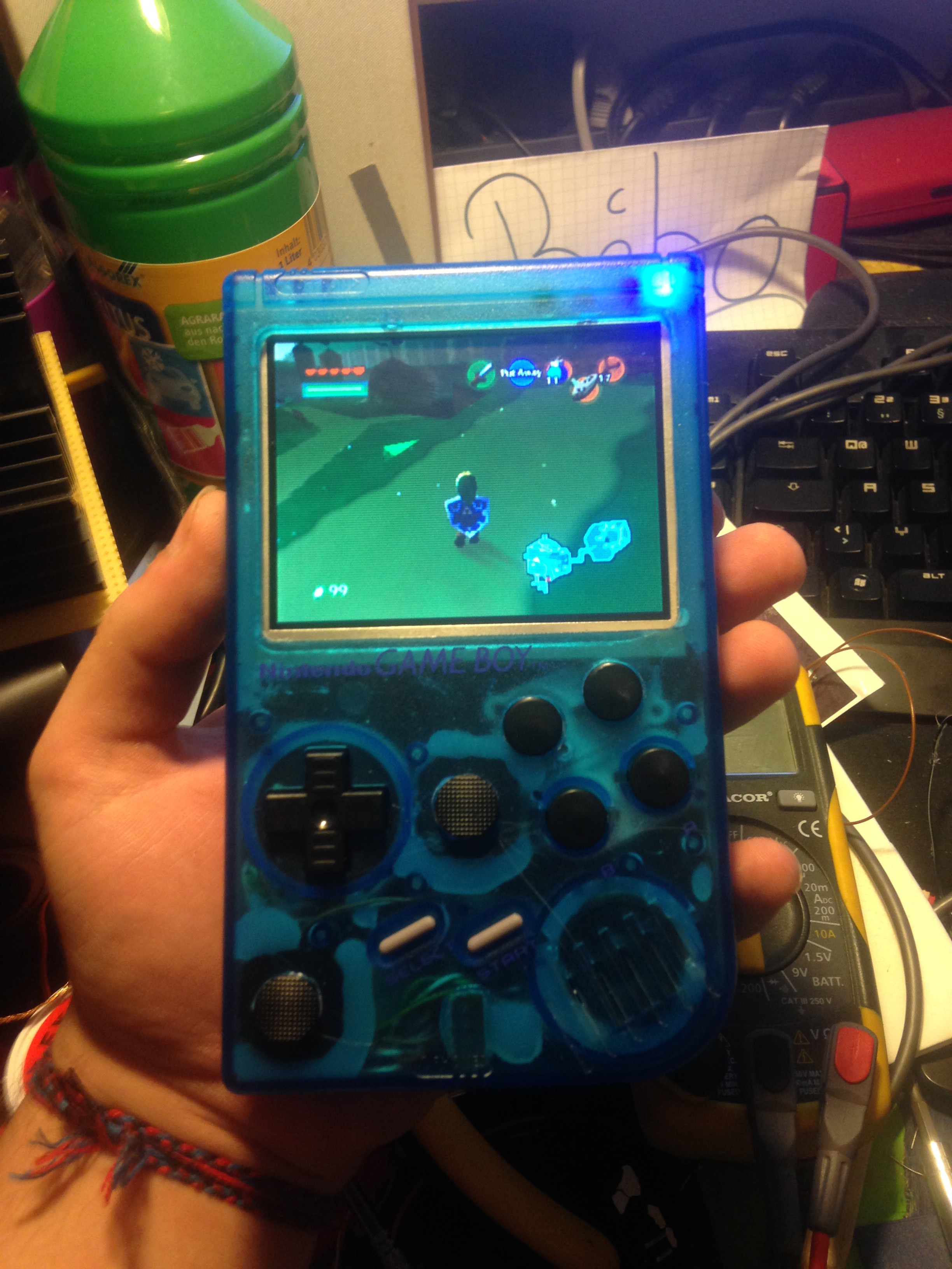
Raspberry Pi 3 Gameboy
This is a DIY Raspberry Pi 3 gaming handheld running RetroPie to play all your classics!


Discussions
Become a Hackaday.io Member
Create an account to leave a comment. Already have an account? Log In.
Hey this is awesome, and likely the guide I will follow for building my Pi3Boy . I desire to keep the HDMI port though, how would you approach that?
Are you sure? yes | no