 sotasystems
-
1Step 1
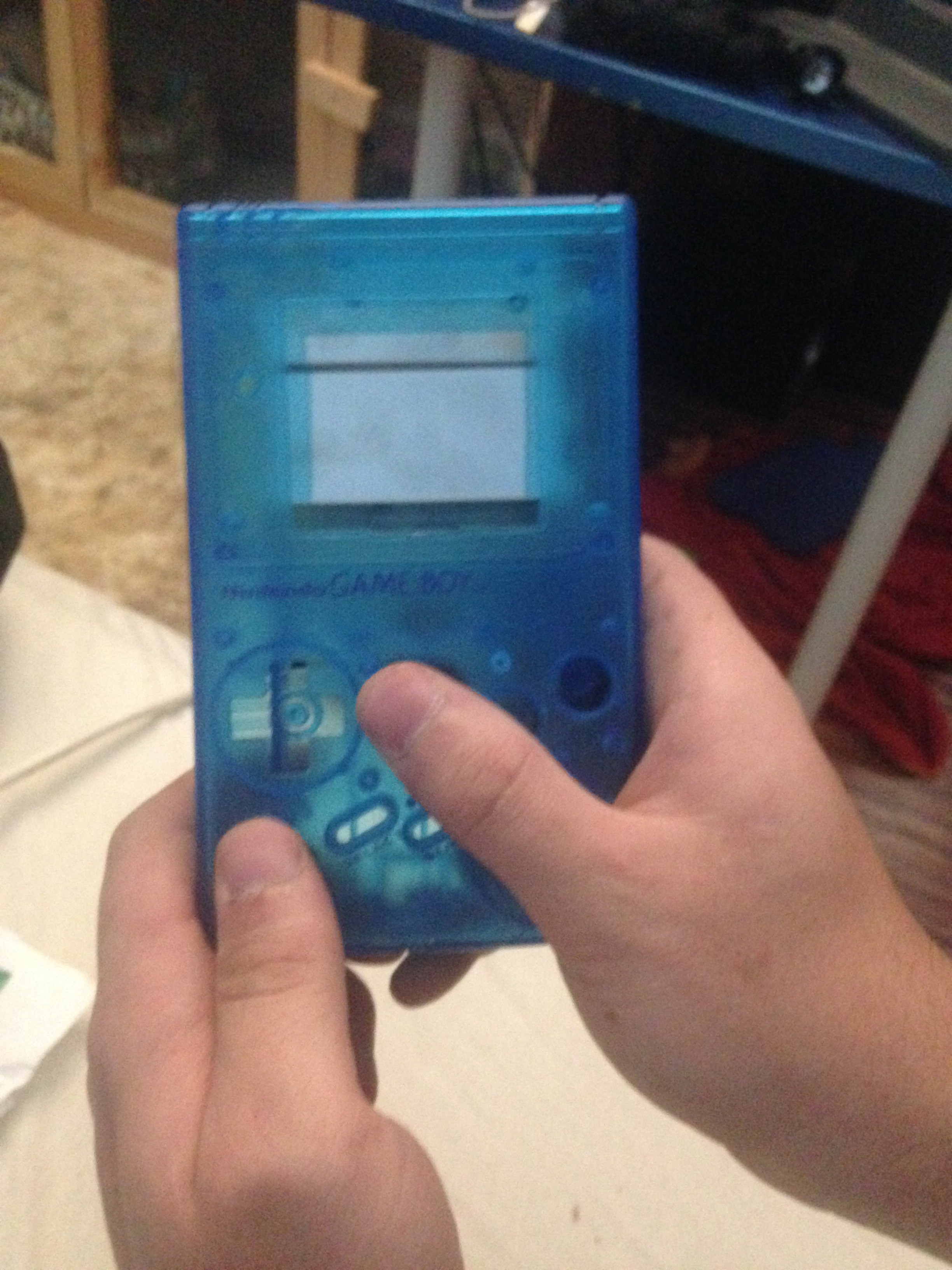
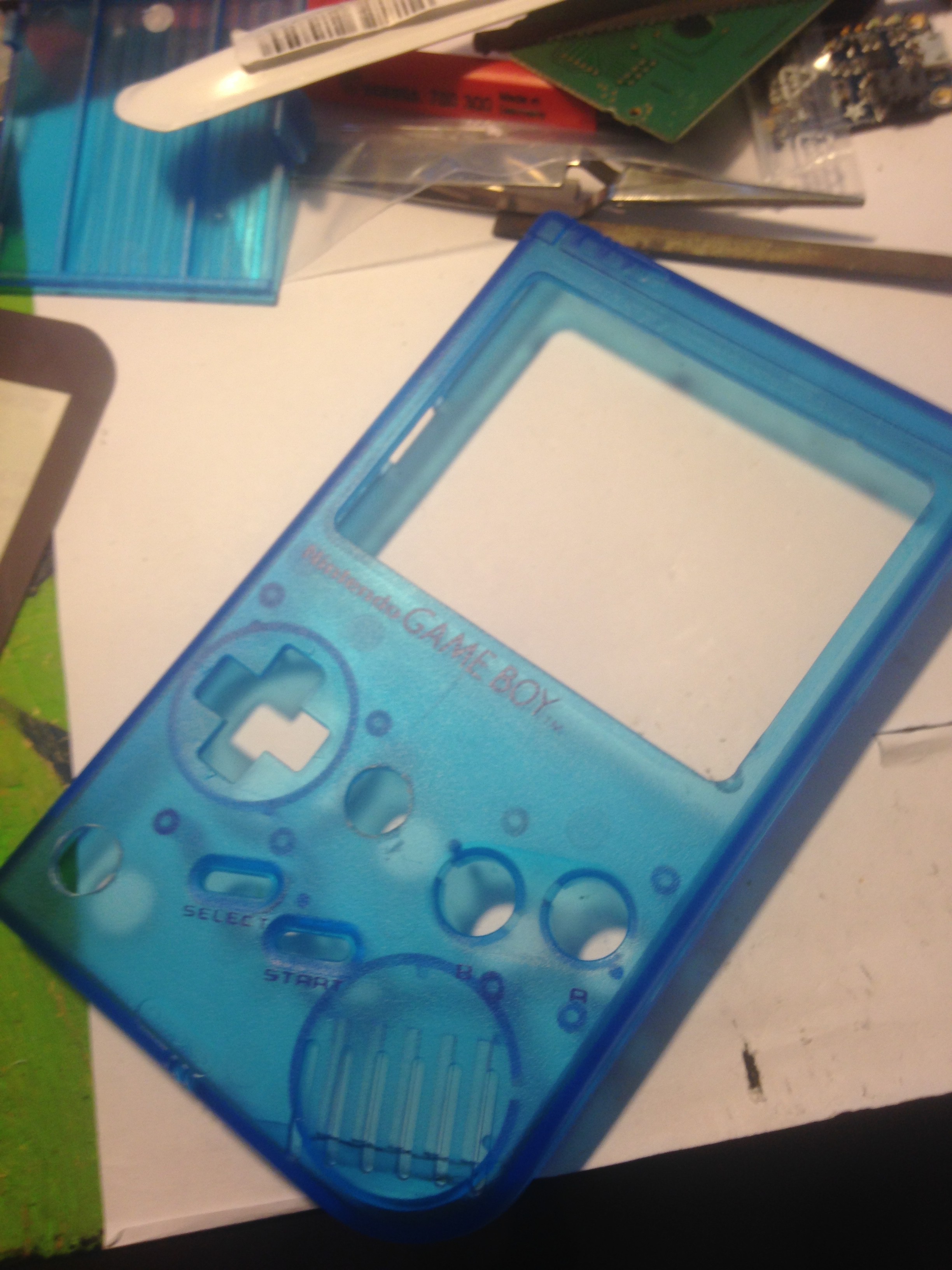
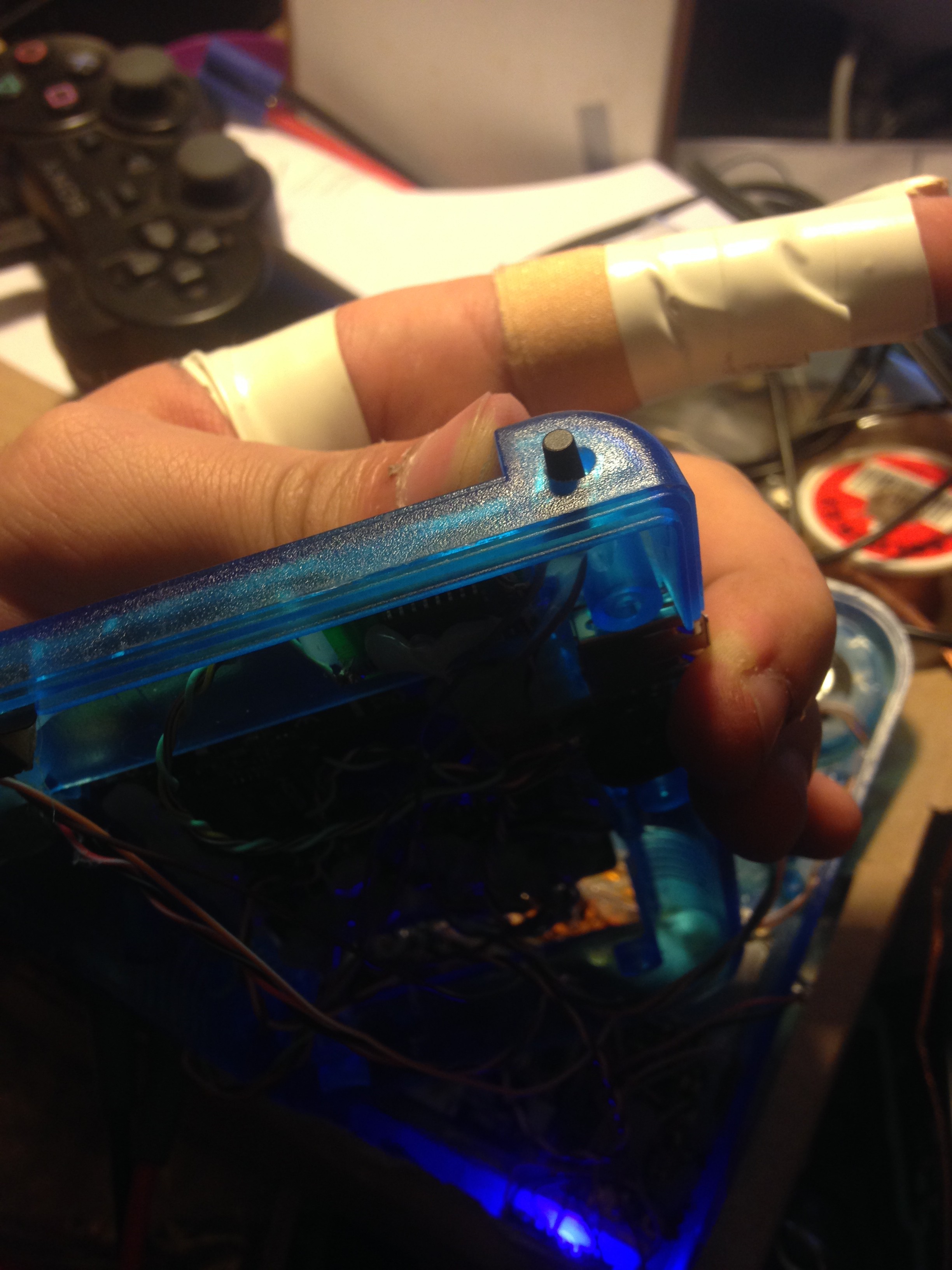
1. Drilling first holes and test fit analog sticks
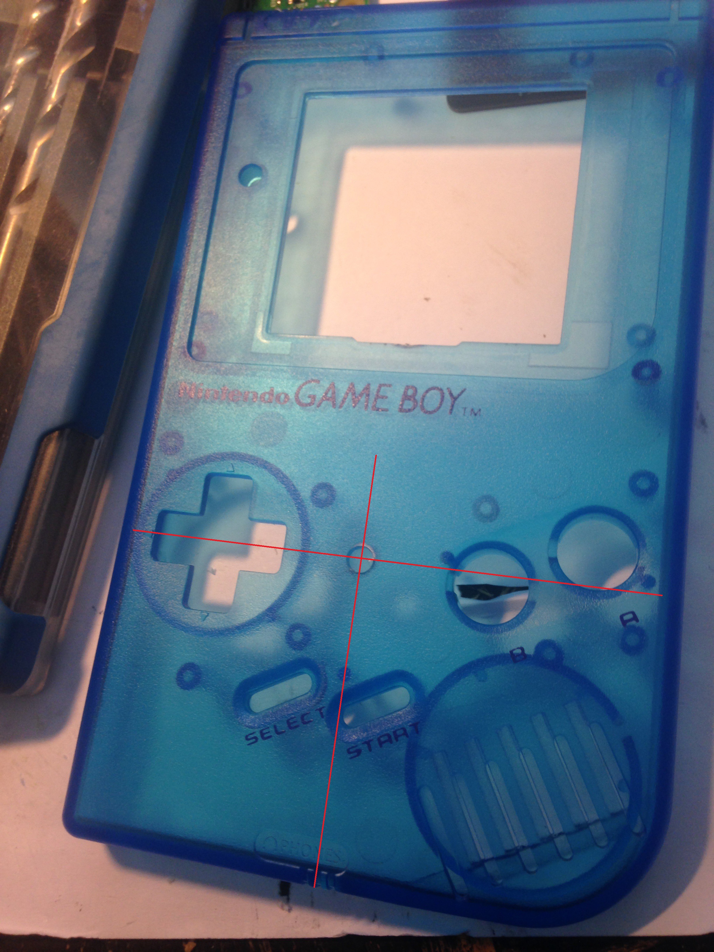
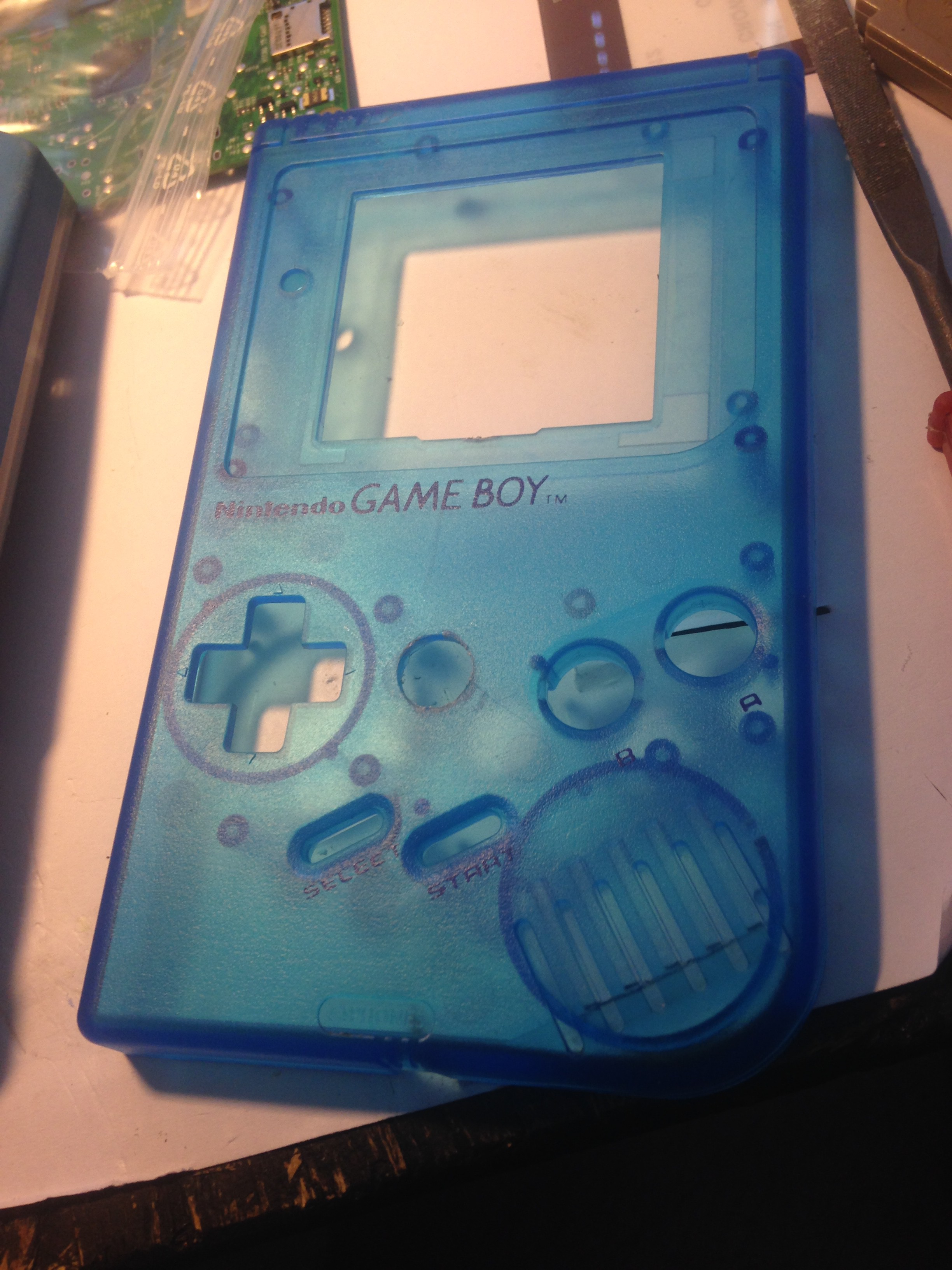
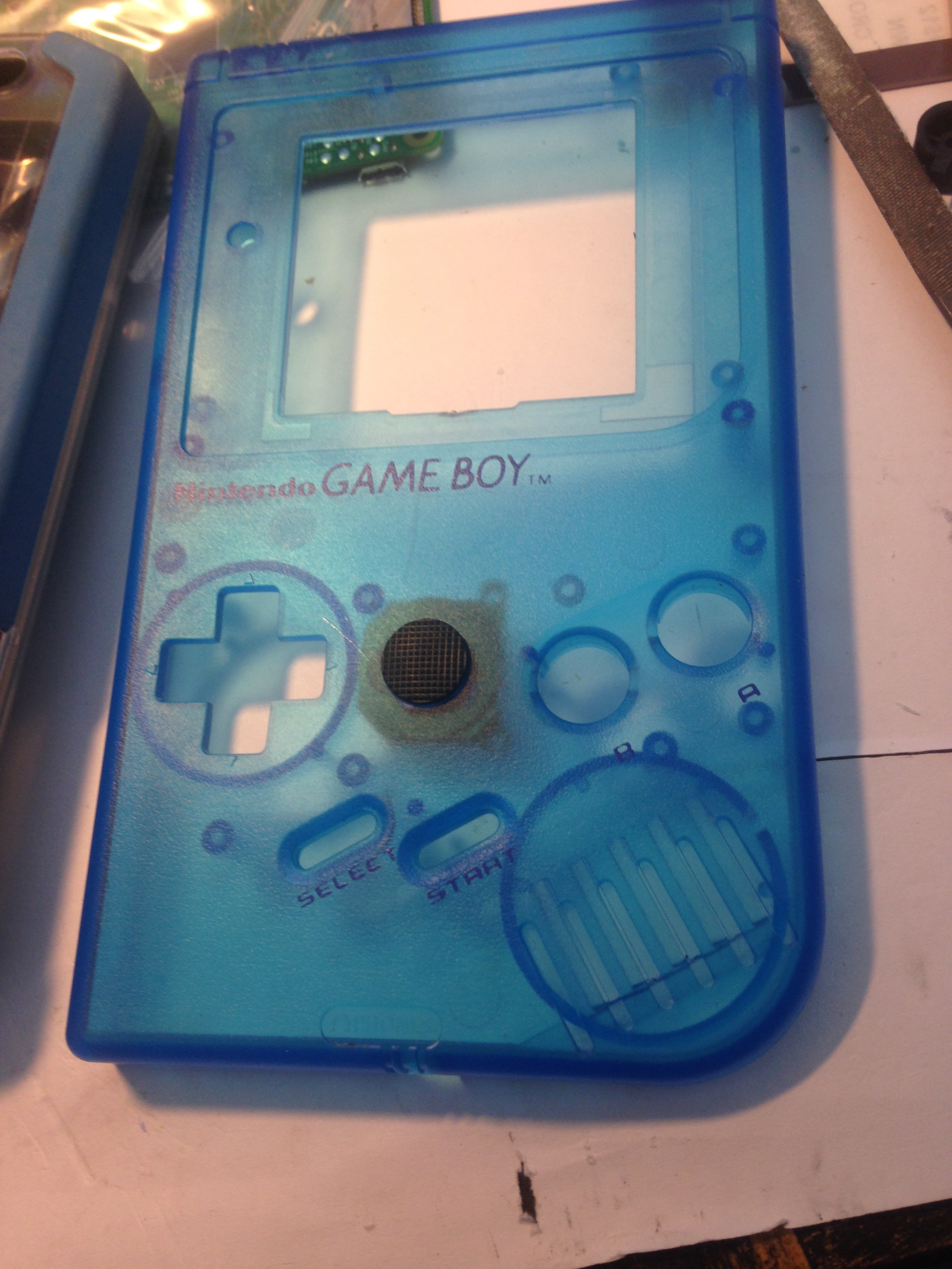
Drill a hole in the center of your gameboy shell to fit the first analog stick (I used a 12mm drill and a file):
![]()
![]()
![]()
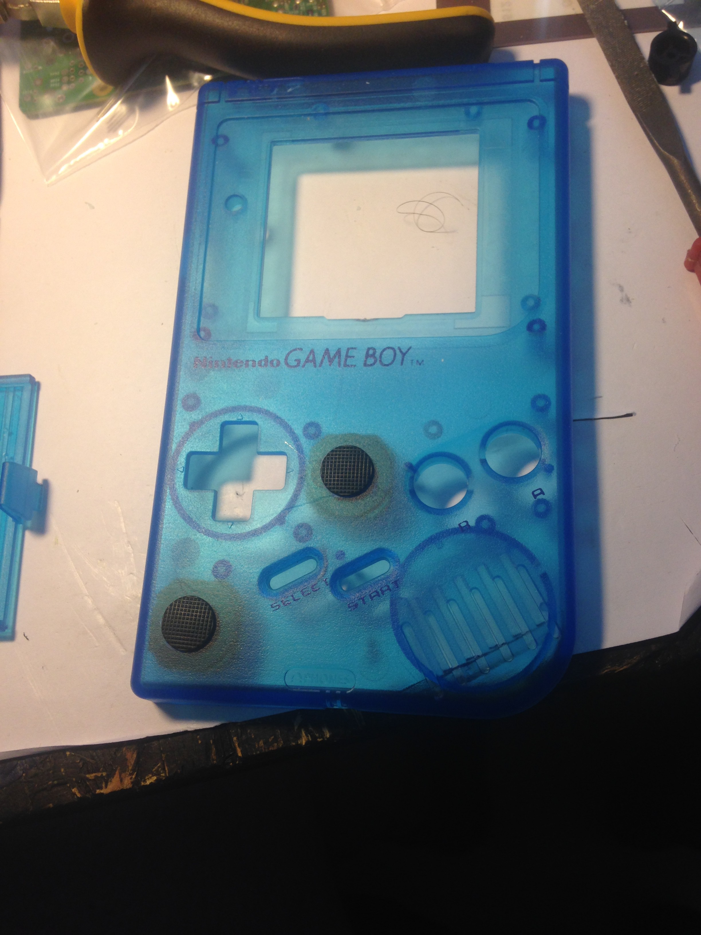
If you are happy with it, do the same for the lower left for the second analog stick:
![]()
![]()
Also, it is a good idea to drill the holes for the X and Y buttons NOW. I have included a drill template (DMG_4button_rev1_drill_template.pdf) for the X and Y buttons in this project which has the dimensions for the kitsch-bent common ground control PCB that we are going to use in this project.
-
2Step 2
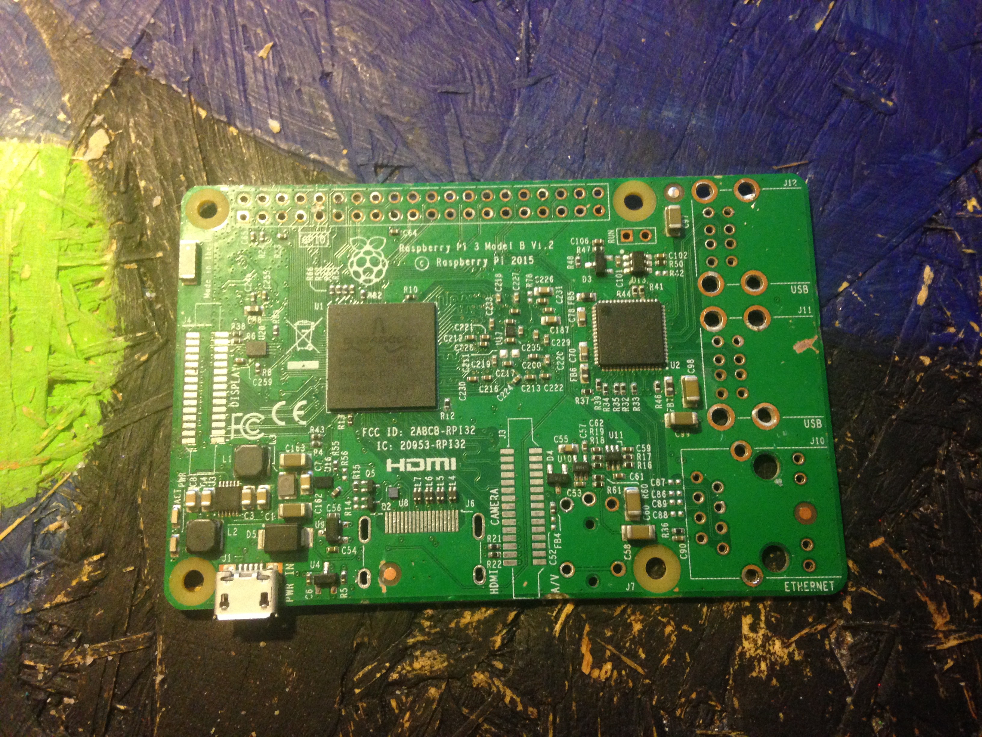
2. Stripping down the Raspberry Pi 3
In order to fit the Raspberry Pi 3 into the gameboy better, we have to strip it down (desolder IO's)
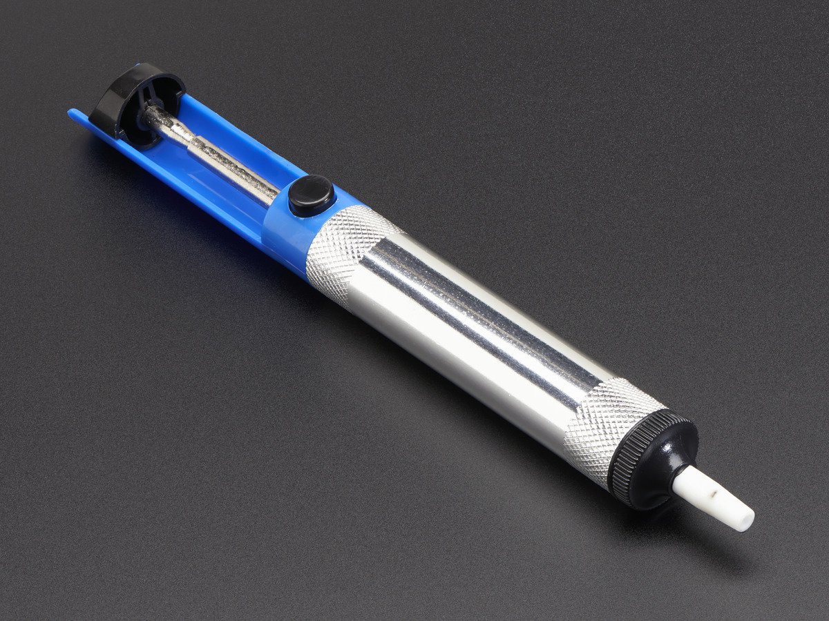
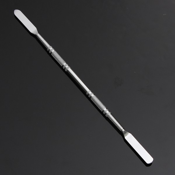
For that I advice you to use at least a desoldering wick, a solder sucker, and a metal prying tool, and of course a little soldering skill is required for this step:
![]()
![]()
![]()
I have used 350 °C on my soldering iron. Use the temparatures you are most comfortable/used with. At the end, you should end up with something like this:
![]()
![]()
-
3Step 3
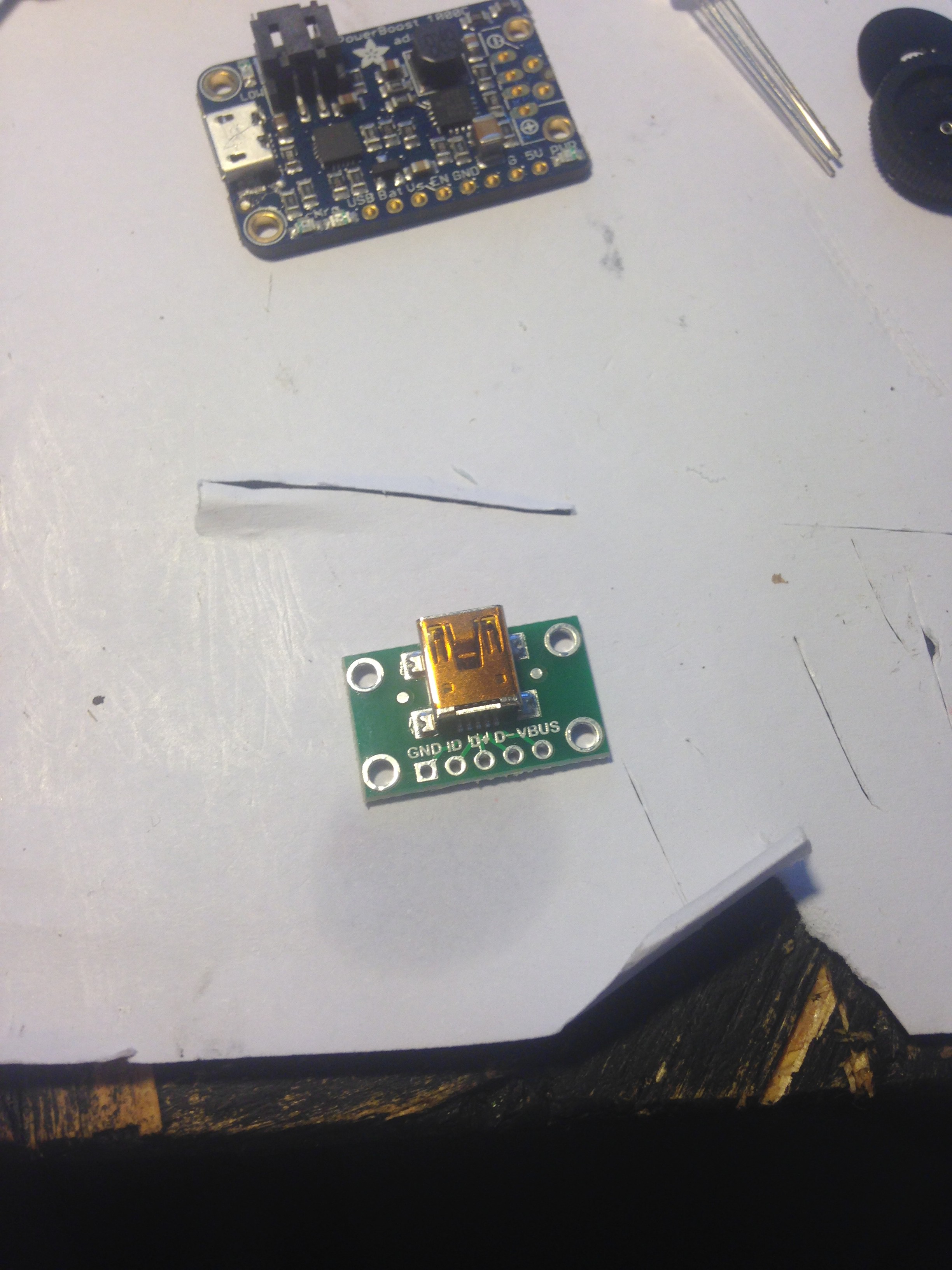
3. Preparing the Mini USB breakout board
The Mini USB breakout board doesn't fit in the original spot for charging the gameboy, it's just a little to bulky, so we have to trim it.
For that I recommend using a hacksaw:
![]()
![]()
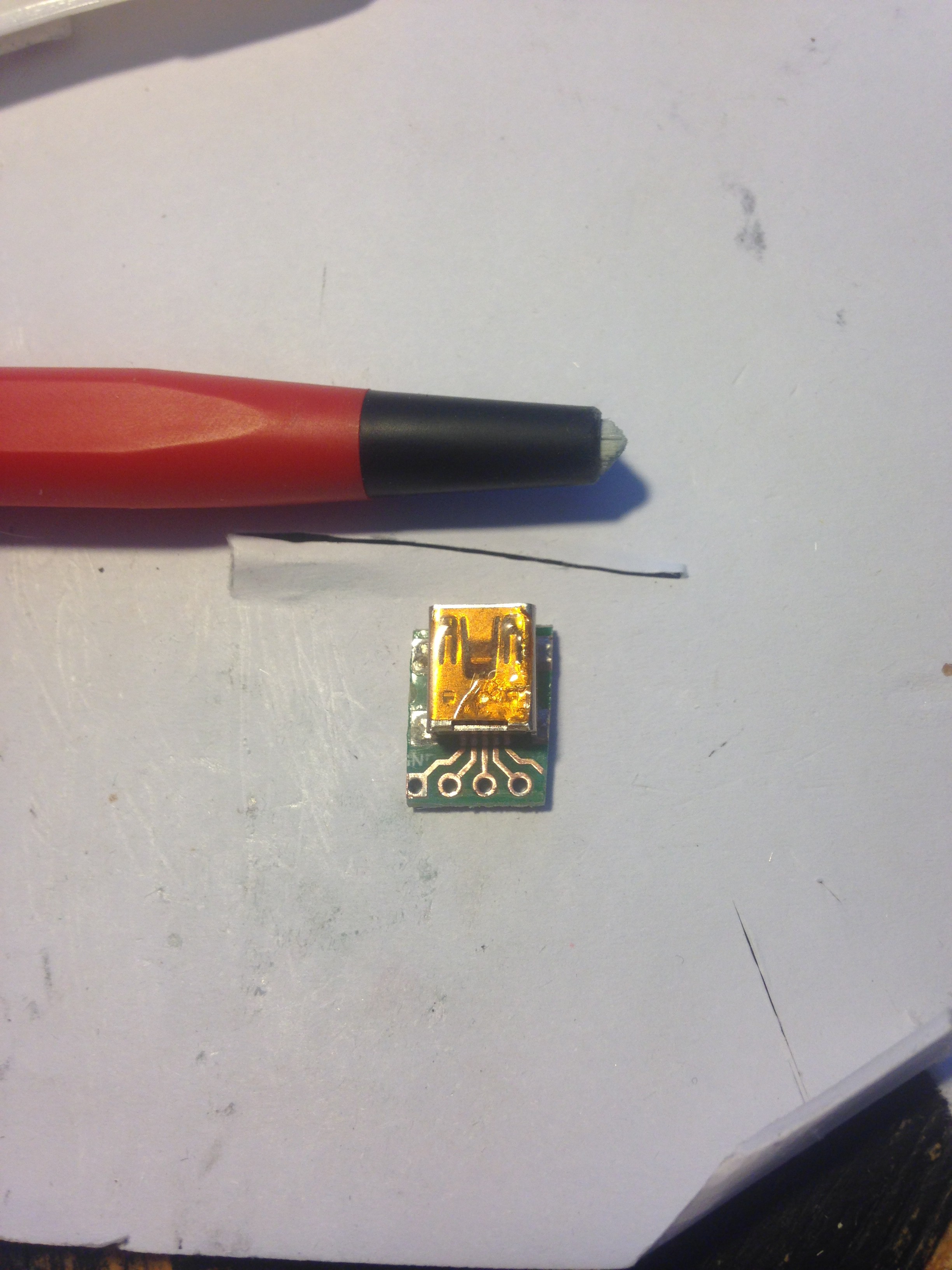
Some pins might get cut off, but that is OK, because we can still use the ones near the center. To gain access to them, I recommend using a glass-fibre pen to scrape off the PCB's protective film and expose the copper, it's clean and easy:
![]()
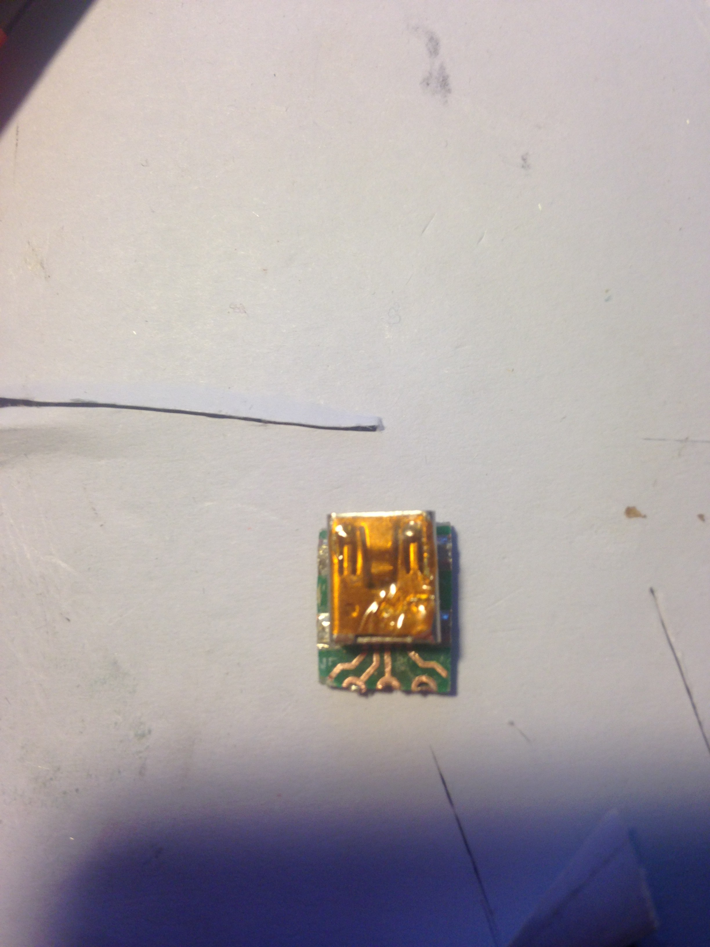
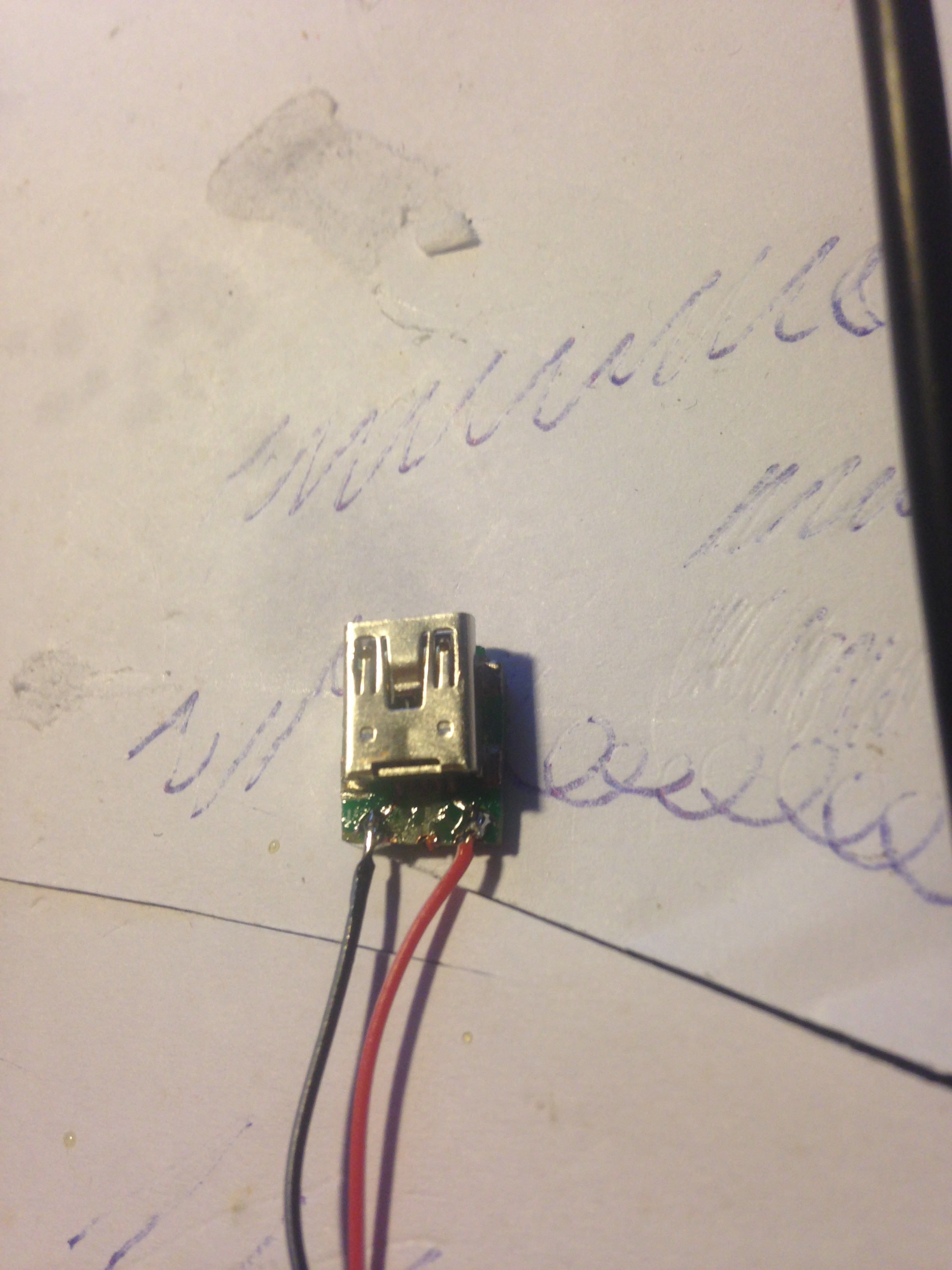
Test fit it again and file it if desired untill it fits fine. For me it looks like this:
![]()
Also, as you can see there, I already have removed one data line with a knife. We have to do this for all remaining lines except 5V and GND (far left and far right), as we only need those and don't want to interfere with chargers that might get upset when connecting 5V or GND to the data lines.
After that is done, you can solder on the wires to the 5V and GND lines:
![]()
-
4Step 4
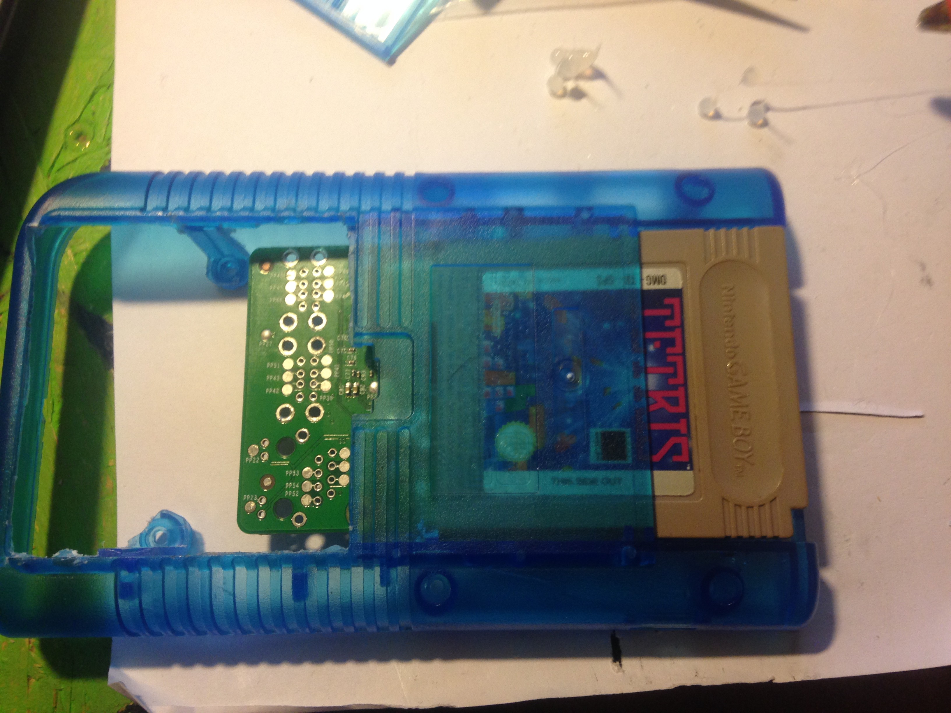
4. Modifying the gameboy and cartridge shell to fit components
In order to fit the screen, the screen area needs to be widened.
I recommend using a file or dremel tool for that:
![]()
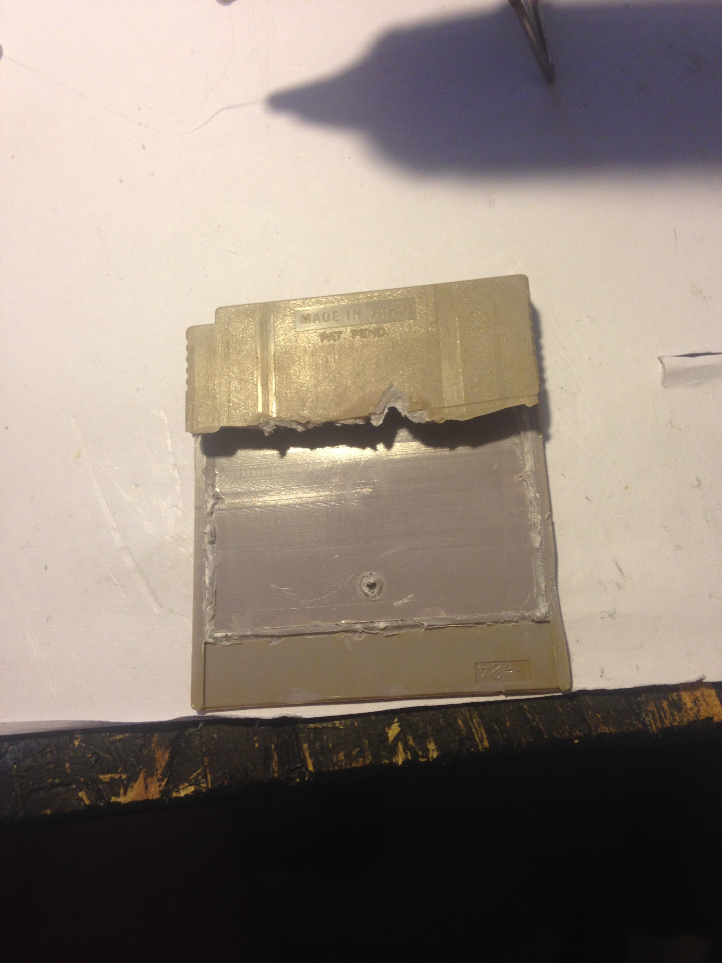
Take the tetris cartridge apart and cut the lower part around the line as good as possible. Also cut down all the posts inside the cartridge. My cartridge was so brittle that it literaly fell apart when I cut it, but that is OK because you won't see that when it is slotted in the gameboy. Then glue the two halves together with hot glue:
![]()
Most of the battery compartment needs to be removed in the same way as the screen bezel so the raspberry pi fits inside, keep in mind to leave on the two screw posts, though:
![]()
![]()
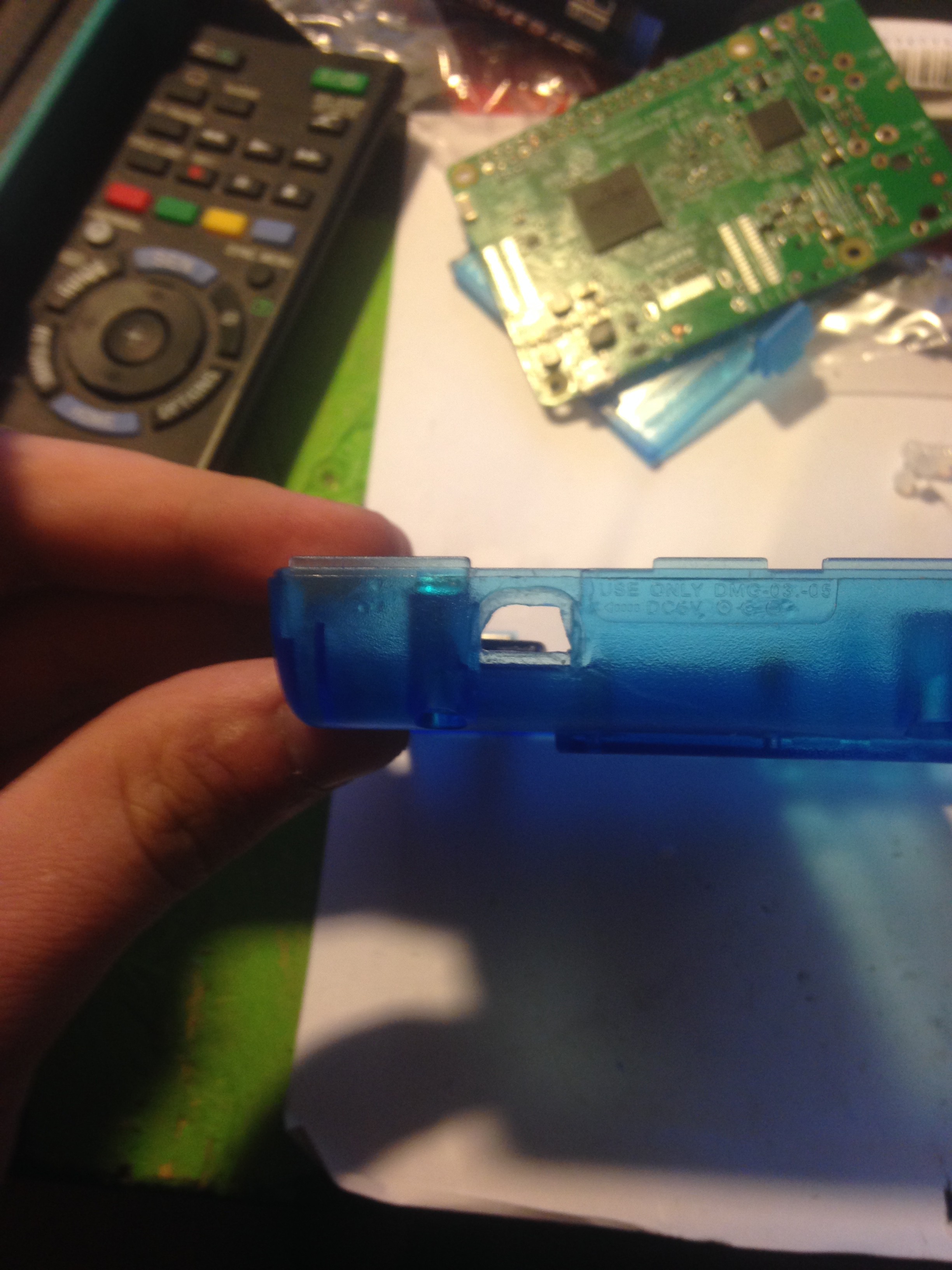
Widen the cahrging port with a file too:
![]()
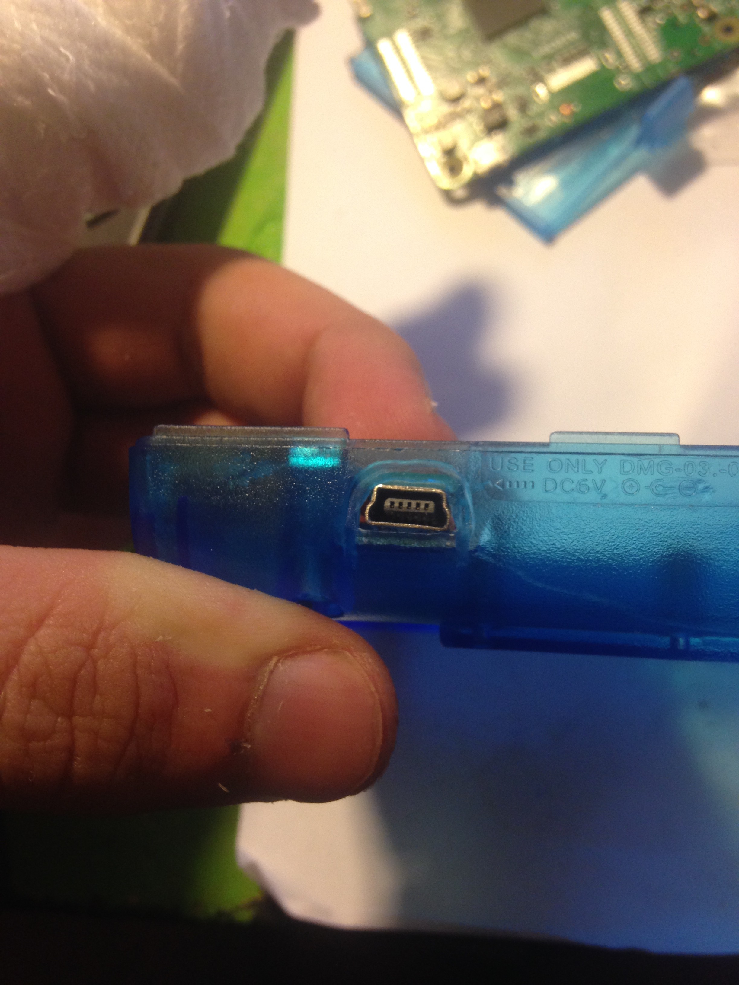
Then you can glue in the charging port:
![]()
-
5Step 5
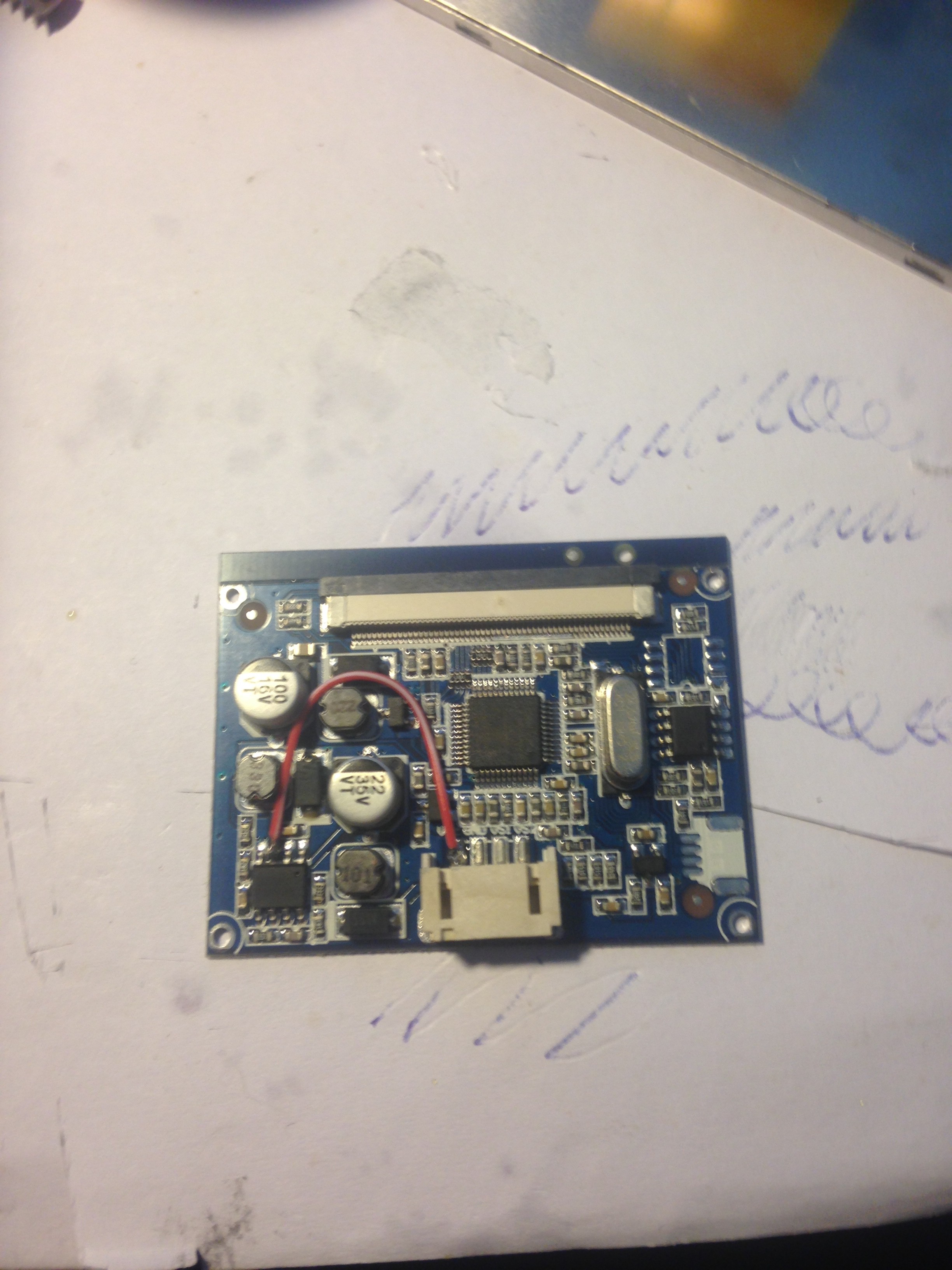
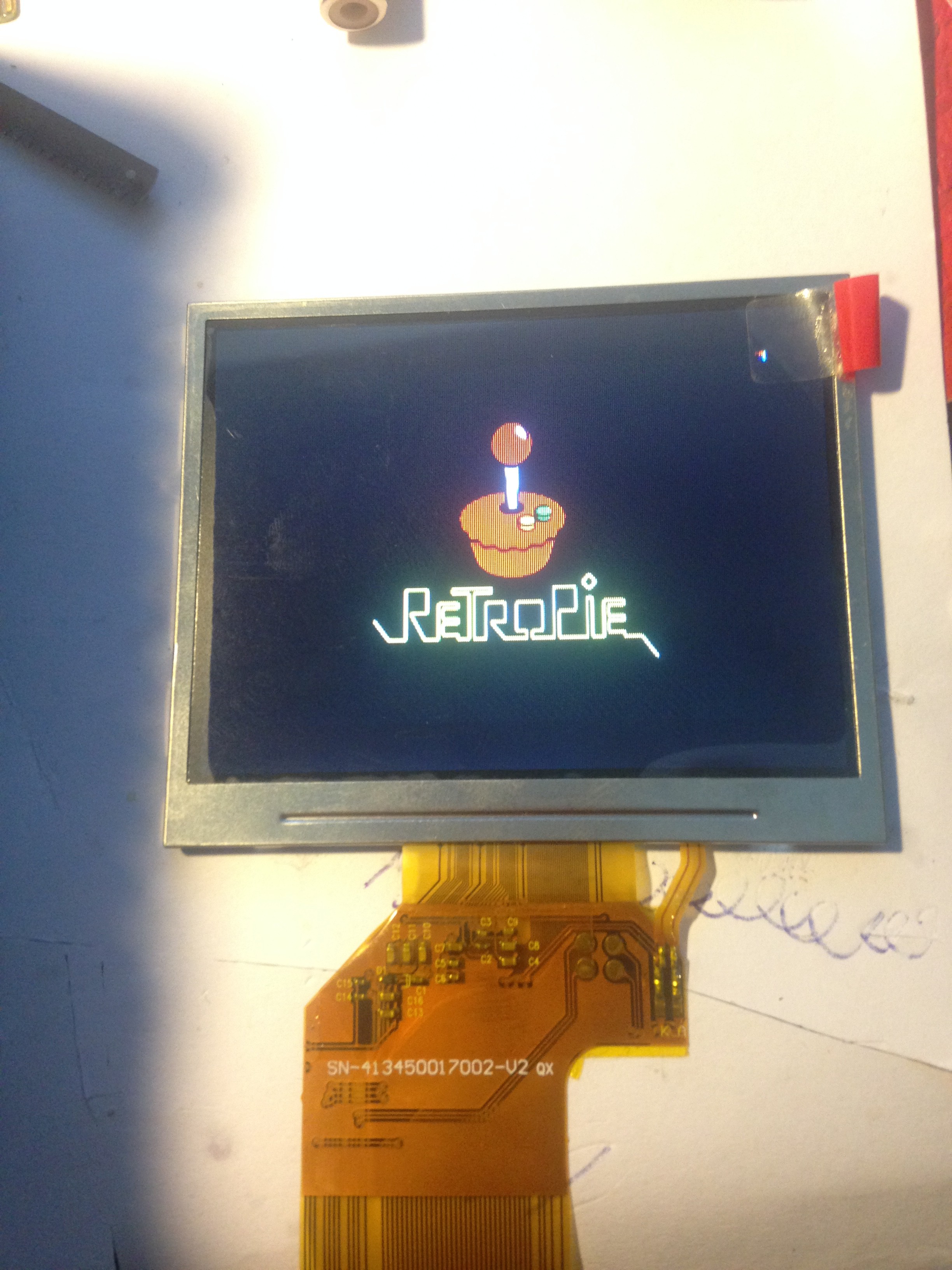
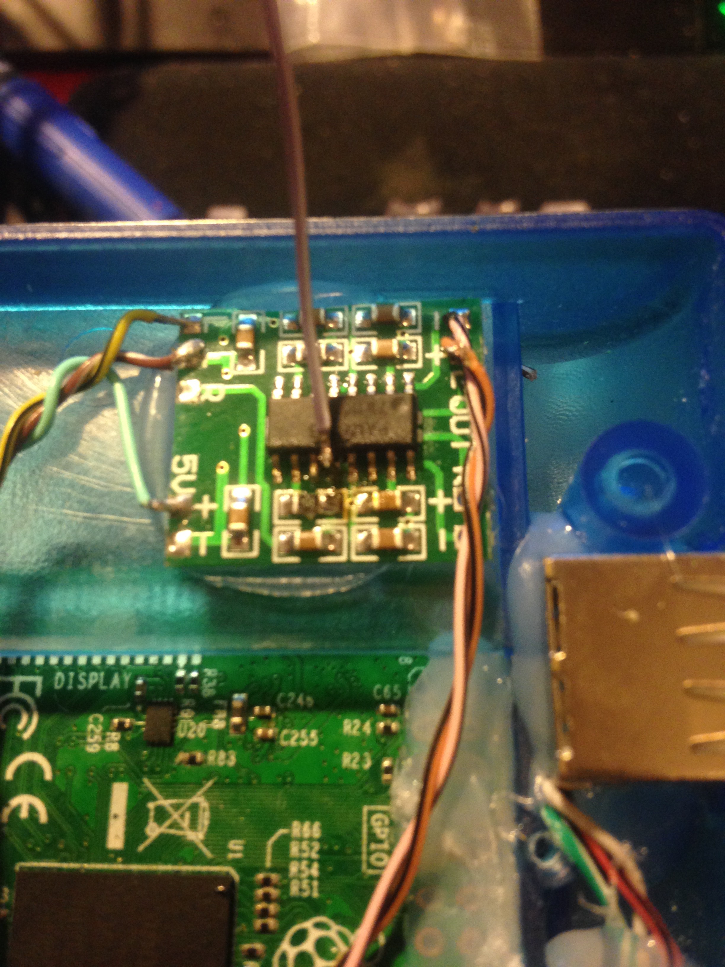
5. Modifying the screen to work with 5 Volts
The screen won't work with 5 Volts out of the box, so it needs to be modified a litlle.
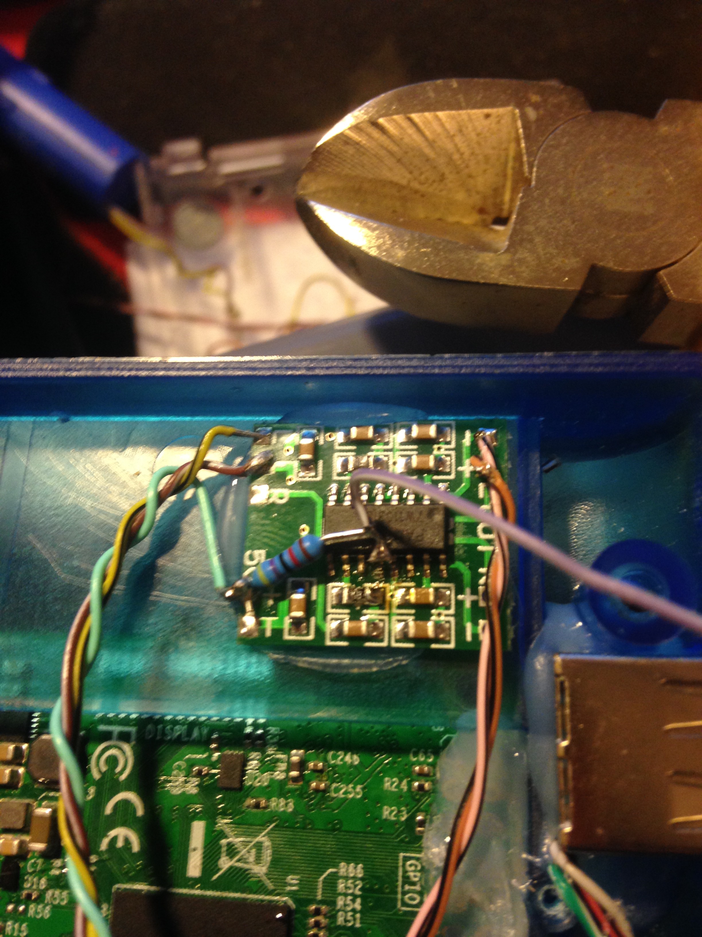
For that, you need to solder a wire to the power line and the 2nd pin of the power regulator IC and that does the trick (note that this only works on this very particular board! If you have a board that looks different from this one, it does not work!):
![]()
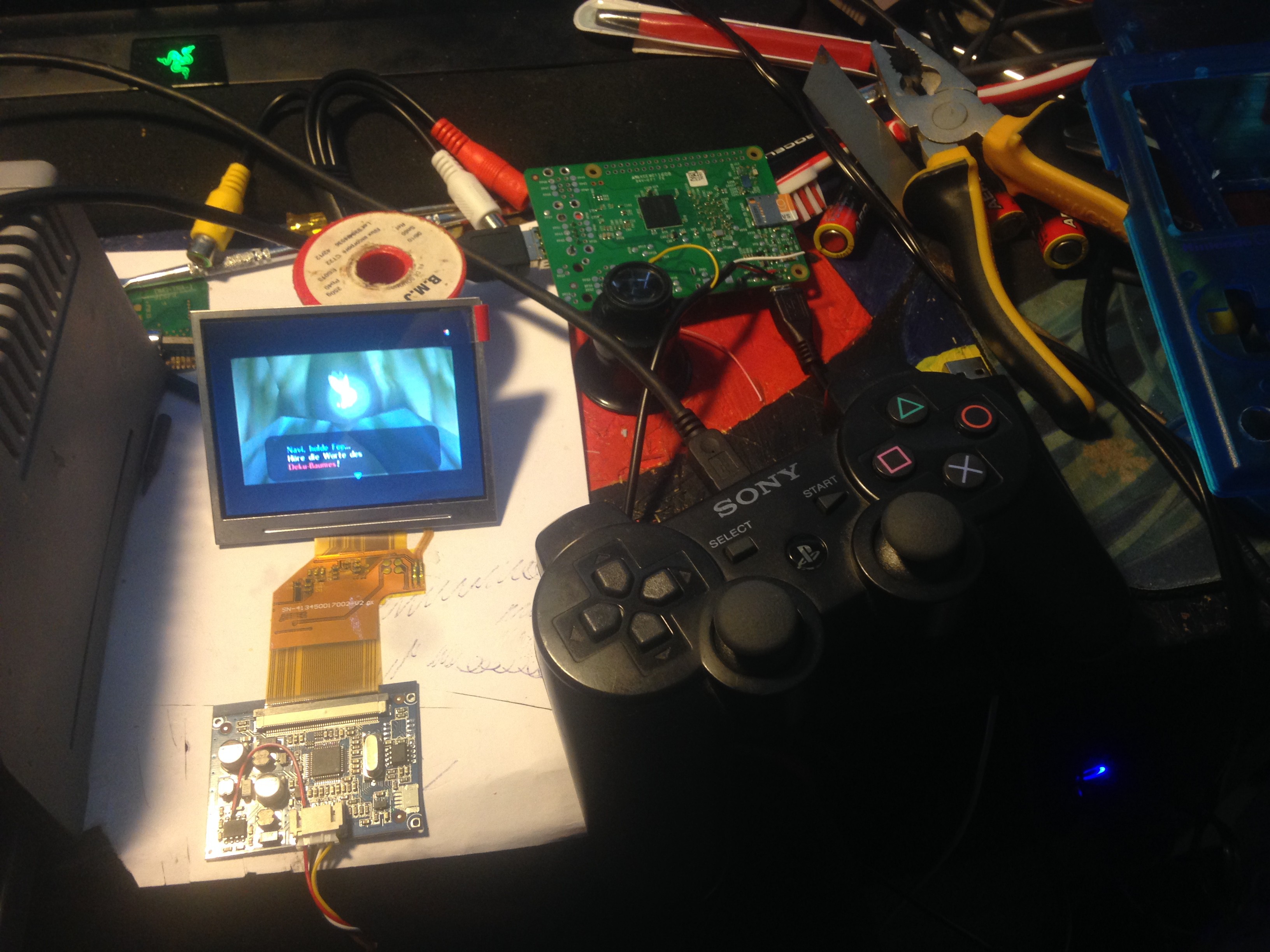
Solder on wires to test it out to the corresponding pins as shown here:
![]()
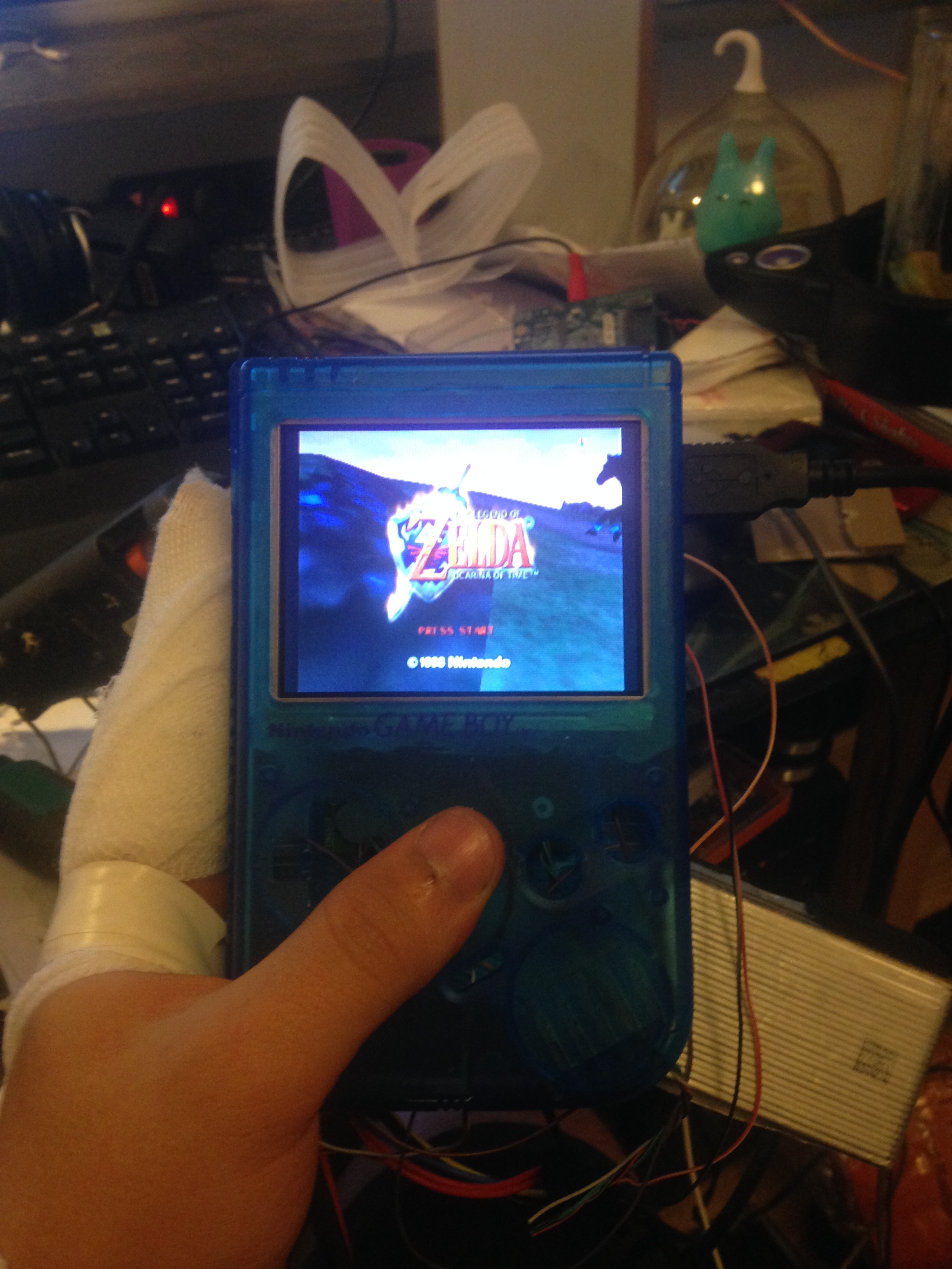
Check if it works.
![]()
![]()
-
6Step 6
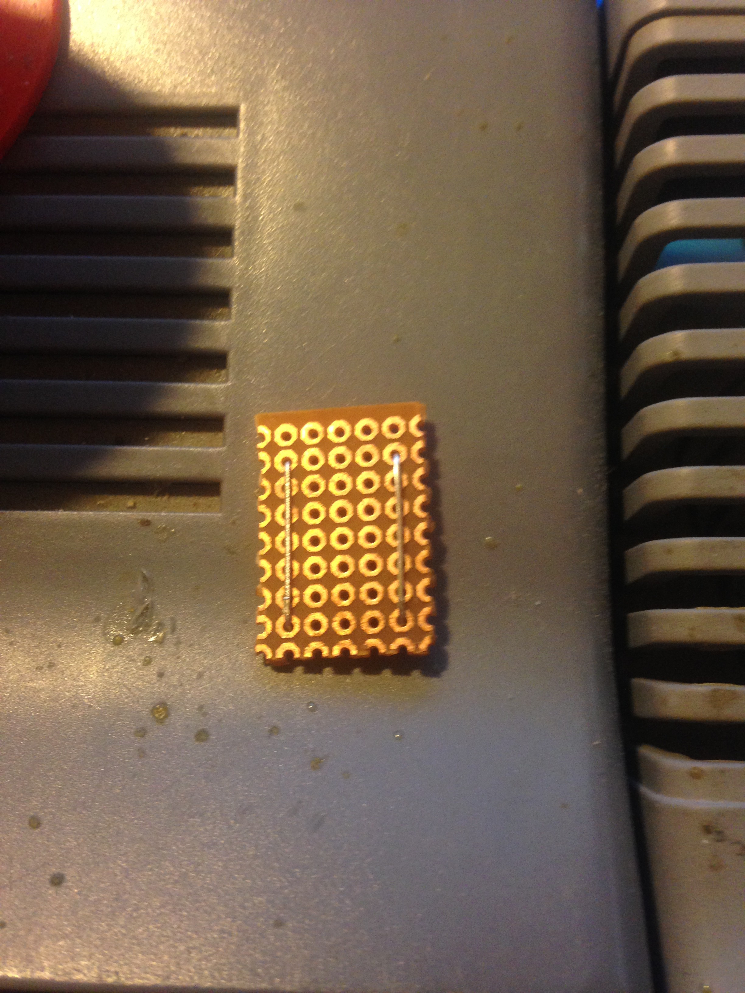
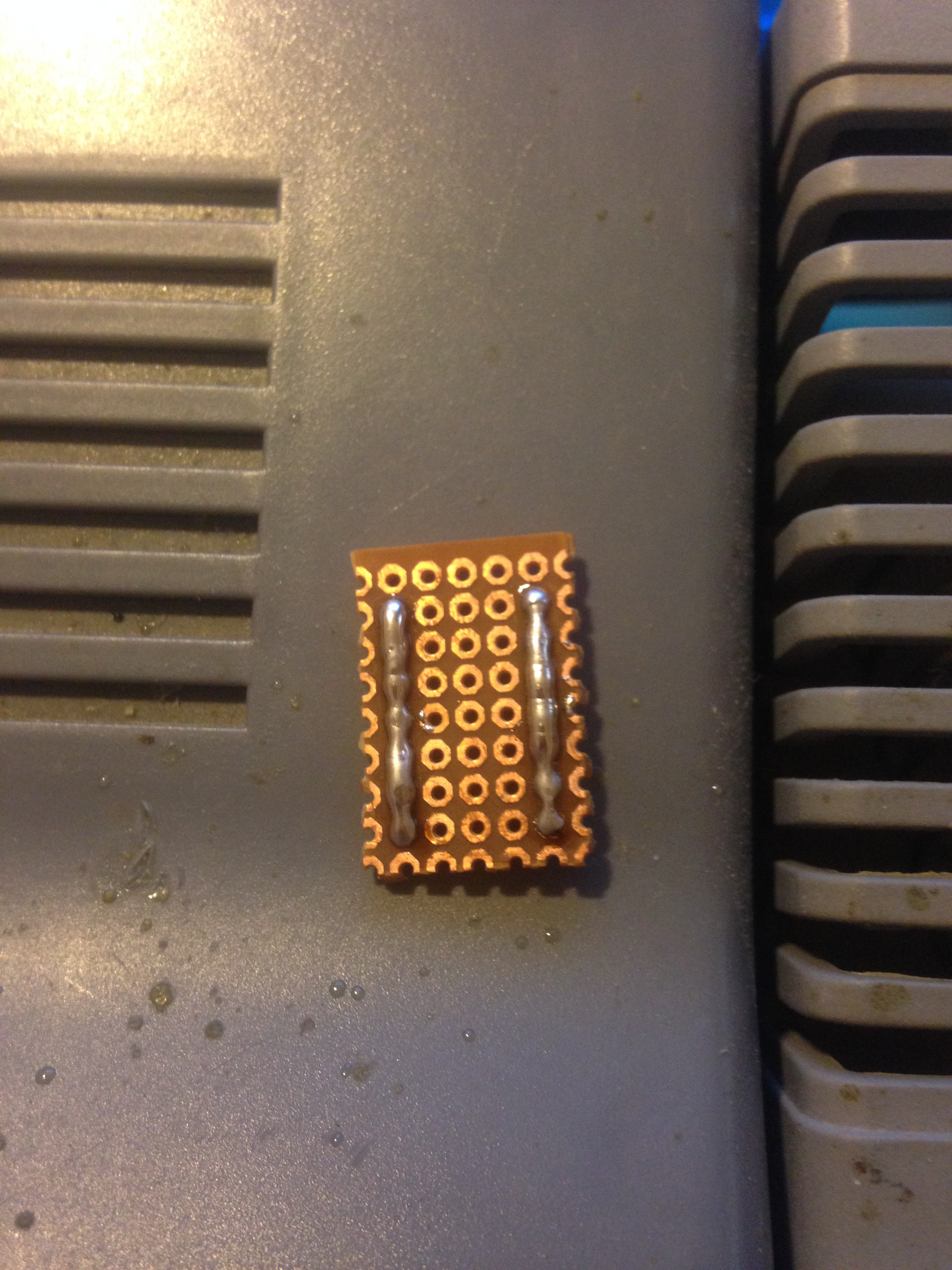
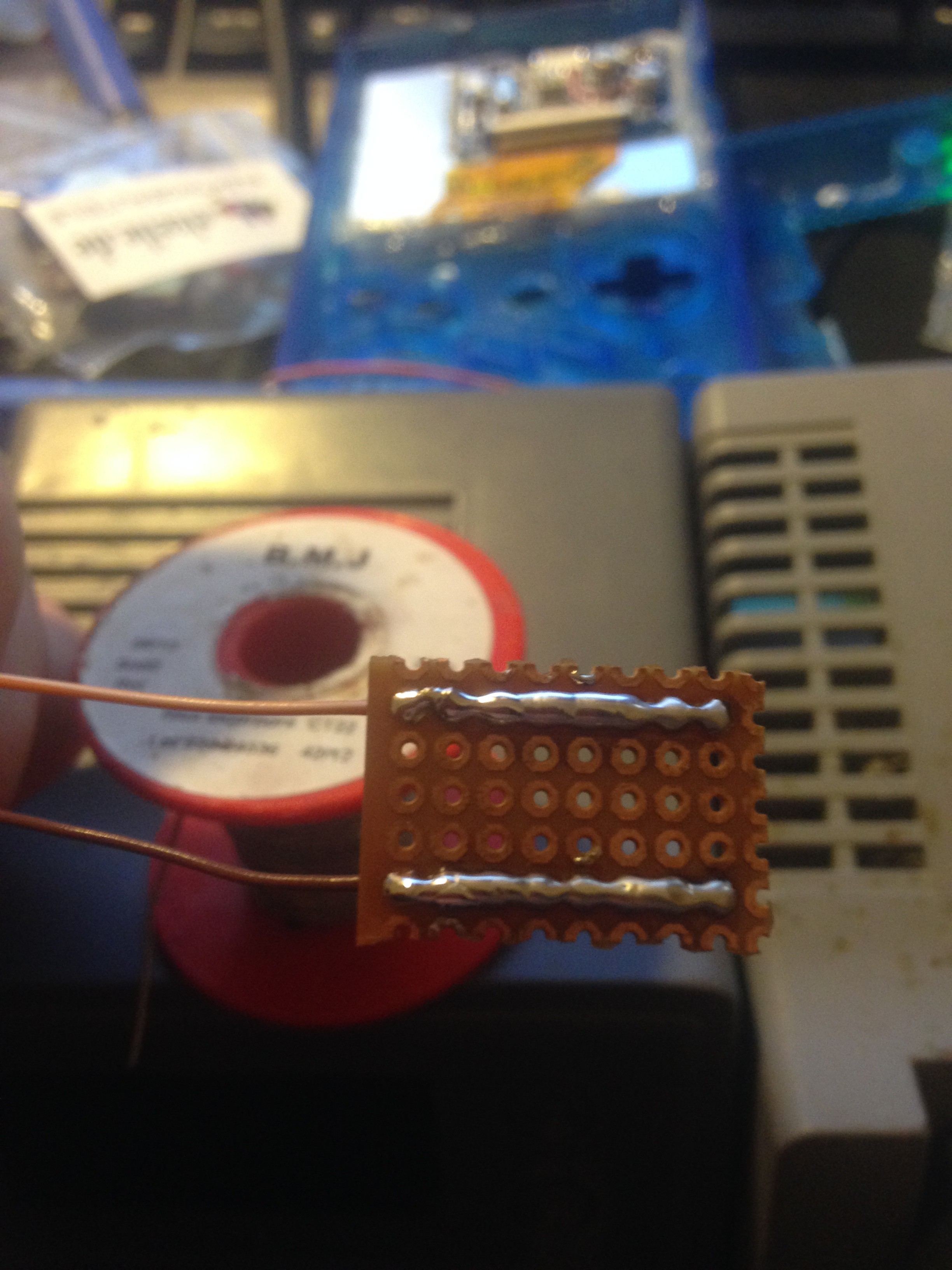
6. Making a small "power distributor"
This step is optional, but it makes things easier later on, so it is recommended.
I made a small "power distributor" for easier hook up for devices that need power. You wire it up directly to the
powerboost's USB output. It is made out of perfboard. You can use two clipped LED/resistor pins to make the rails and then solder it on:
![]()
![]()
![]()
-
7Step 7
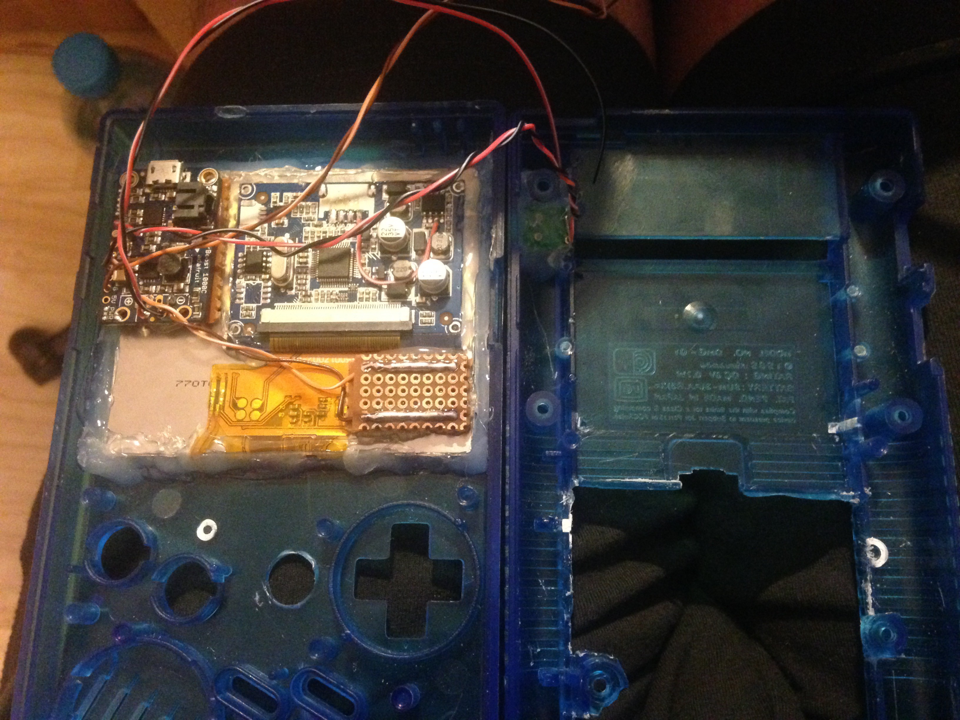
7. Gluing in the screen and some components
Glue in the screen in the place where it is supposed to go, and keep in mind to leave some spacing underneath it to later on still be able to fit in the X and Y buttons. Glue in it's controller with a piece of paper underneath to prevent shorts and the powerboost with a piece of perfboard underneath to prevent shorts and the same for the power rail and wire everything up.
![]()
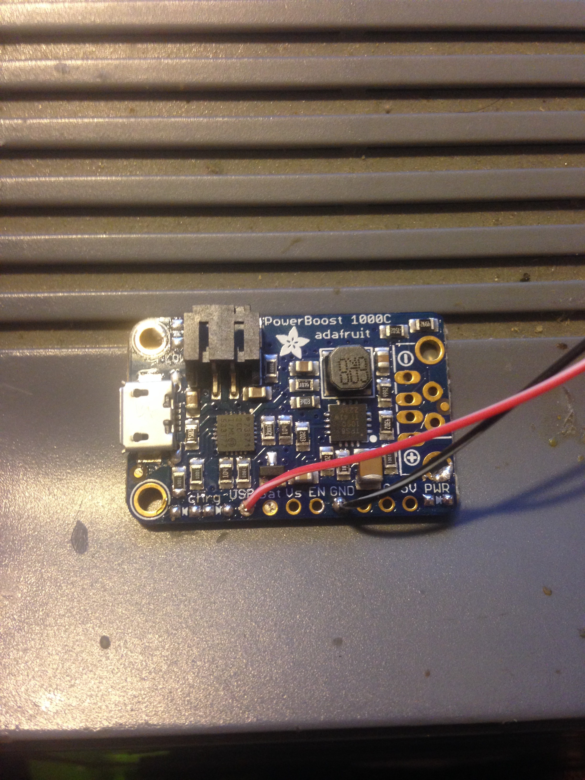
The wires are connected this way: Mini USB + (red wire) to Powerboost USB, and Mini USB - (black wire) to GND:
![]()
And the + USB output to the DIY power rail's + (if you made one, like shown in step 6) and - USB output to the - of the power rail.
It is also a good idea to solder on wires to the EN and G pin and solder them to the slide switch and glue it in place where the original gameboy switch goes.
-
8Step 8
8. Soldering on wires to the Pi and gluing it in
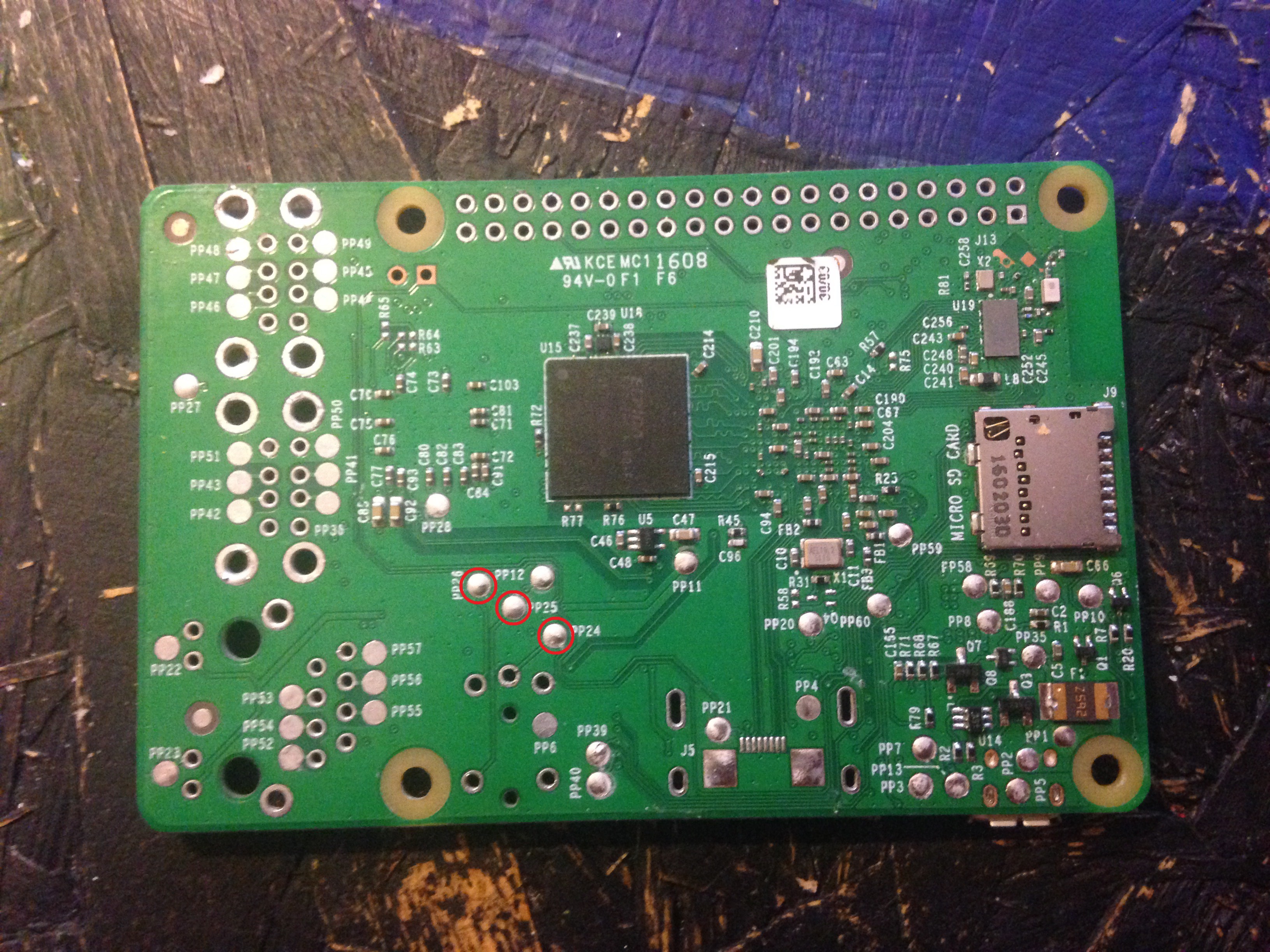
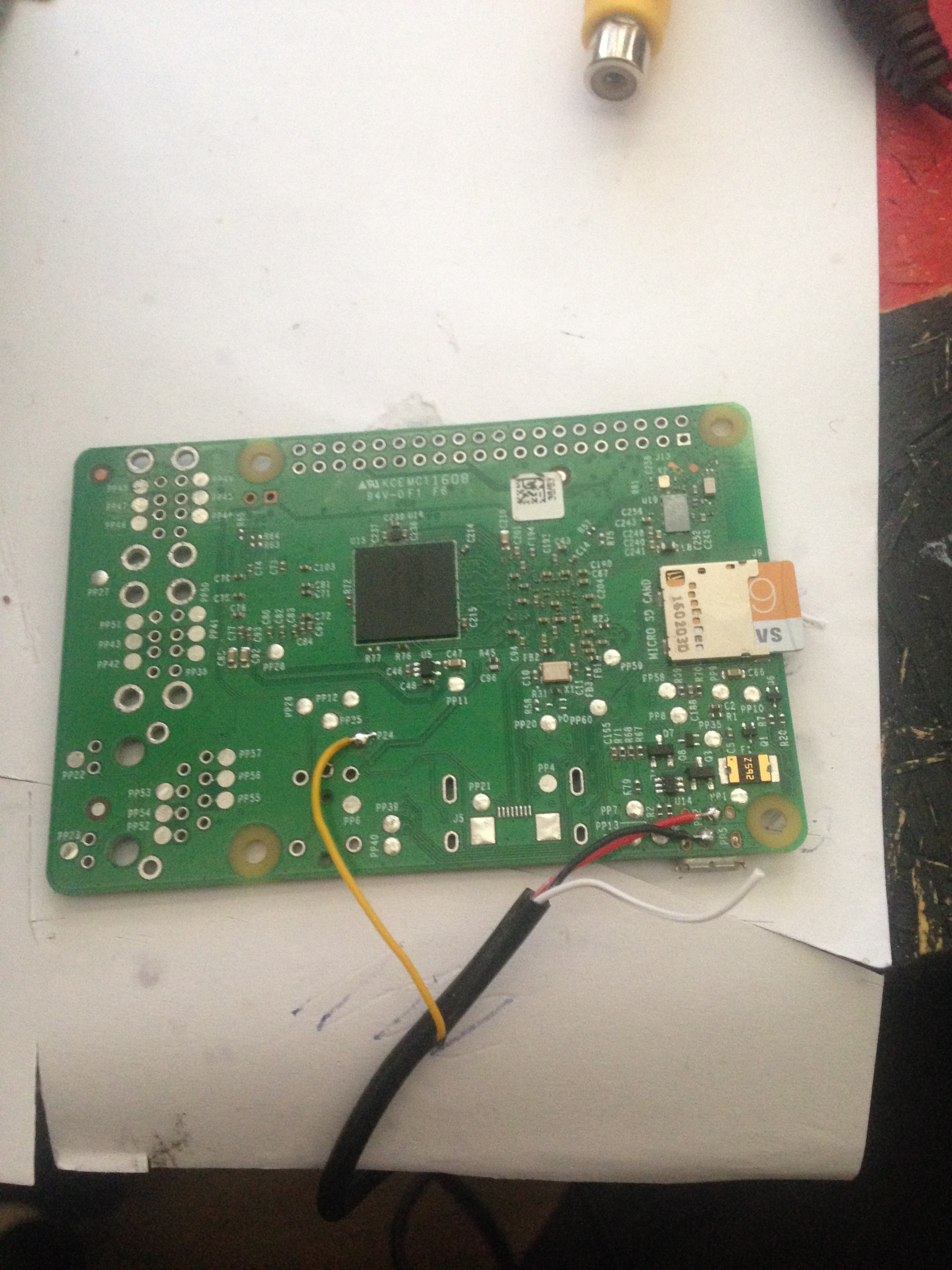
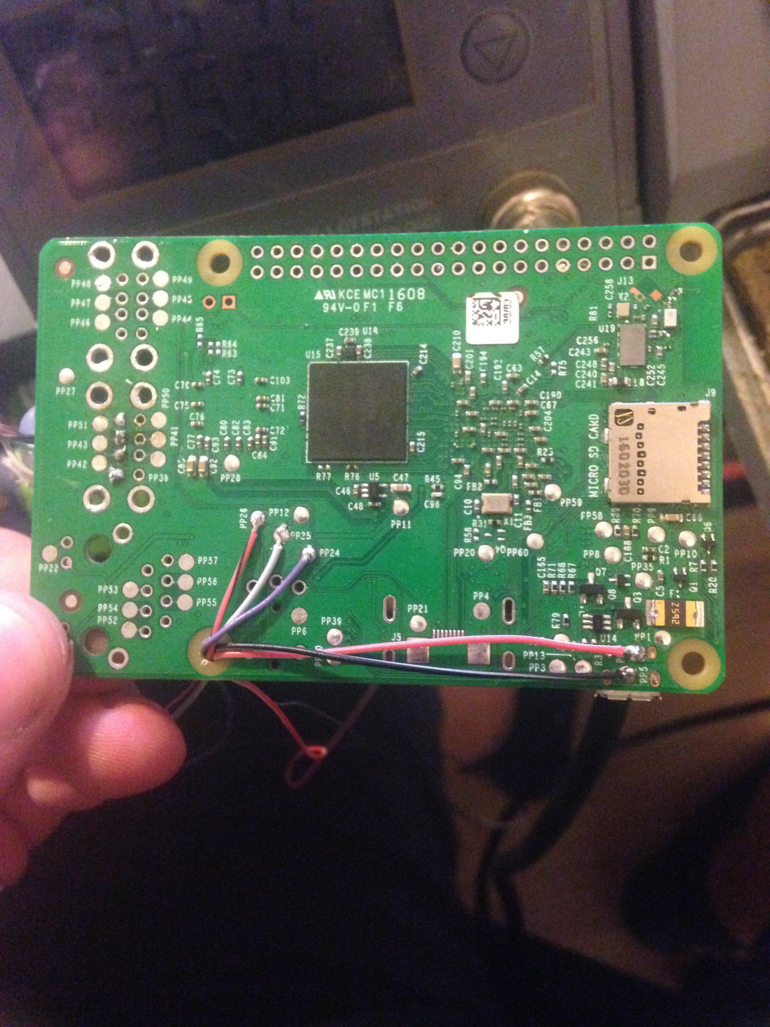
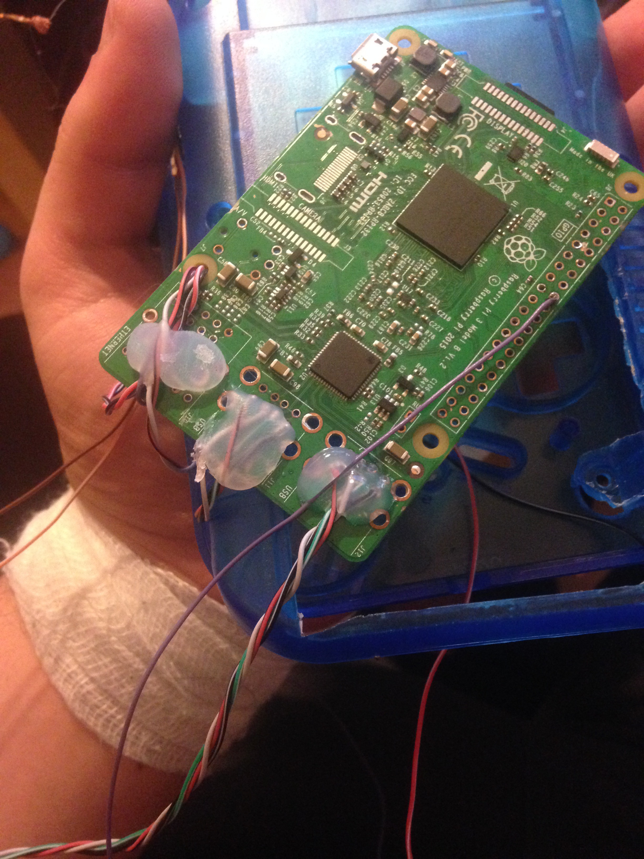
Solder wires to the power input of the Pi, audio and video and solder in 2 sets of 4 wires for USB. One will be used for the USB port, and the other for my leonardo pro micro. Here's what pin is for what:
PP1 - 5V input
PP5 - GND input
PP24 - Composite video out
PP25 - Audio left
PP26 - Audio right
![]()
Also solder in a wire to a GPIO pin number 37 (GPIO26) which will be used to safe-shutdown the Pi later. I later on moved it to another pin not shown in this picture, so make sure it IS pin 37.
![]()
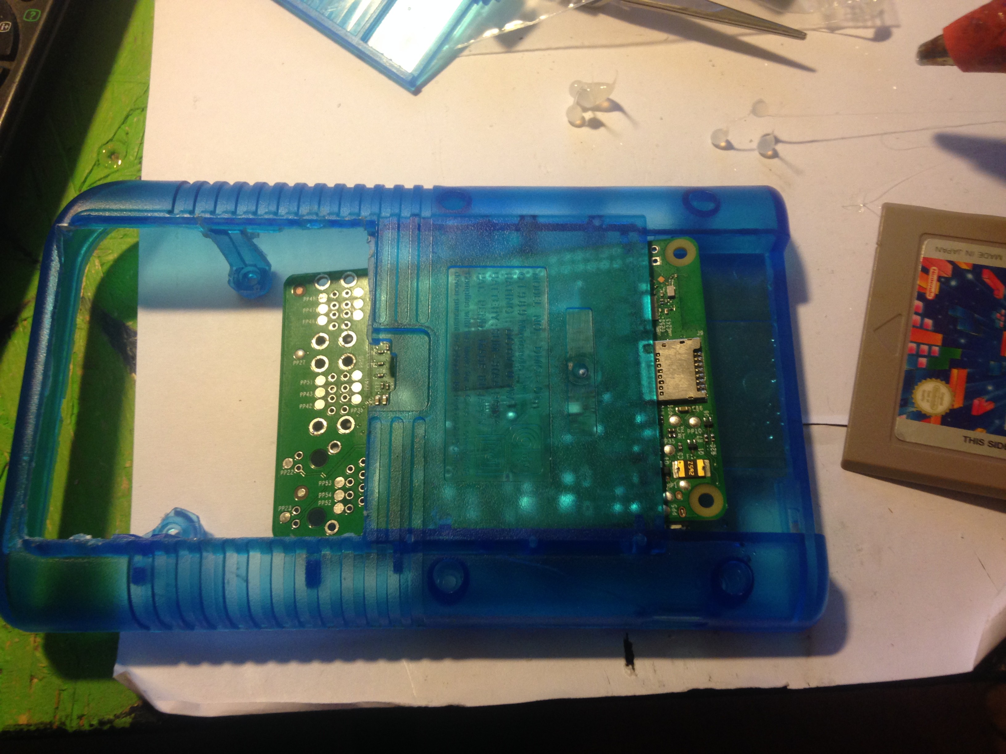
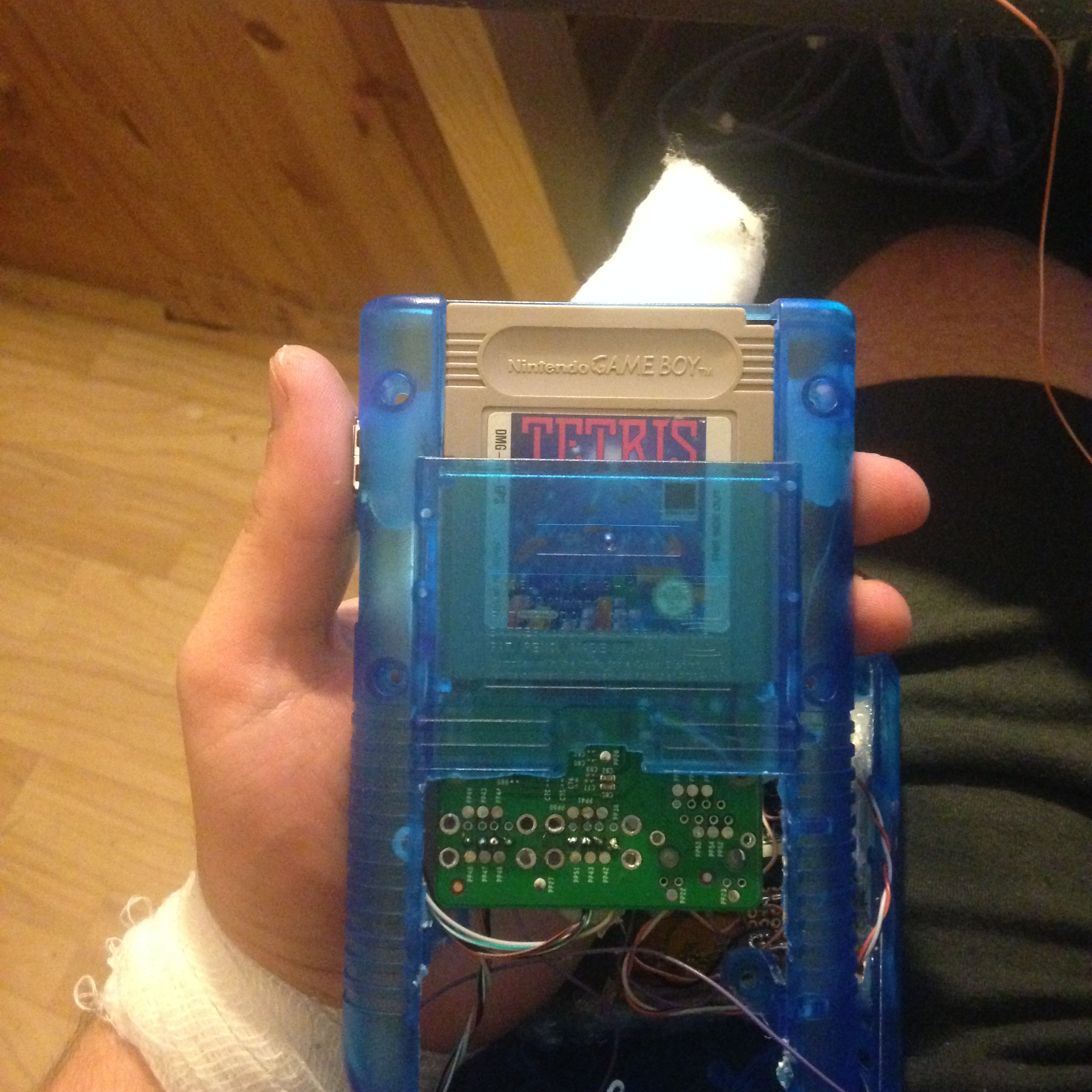
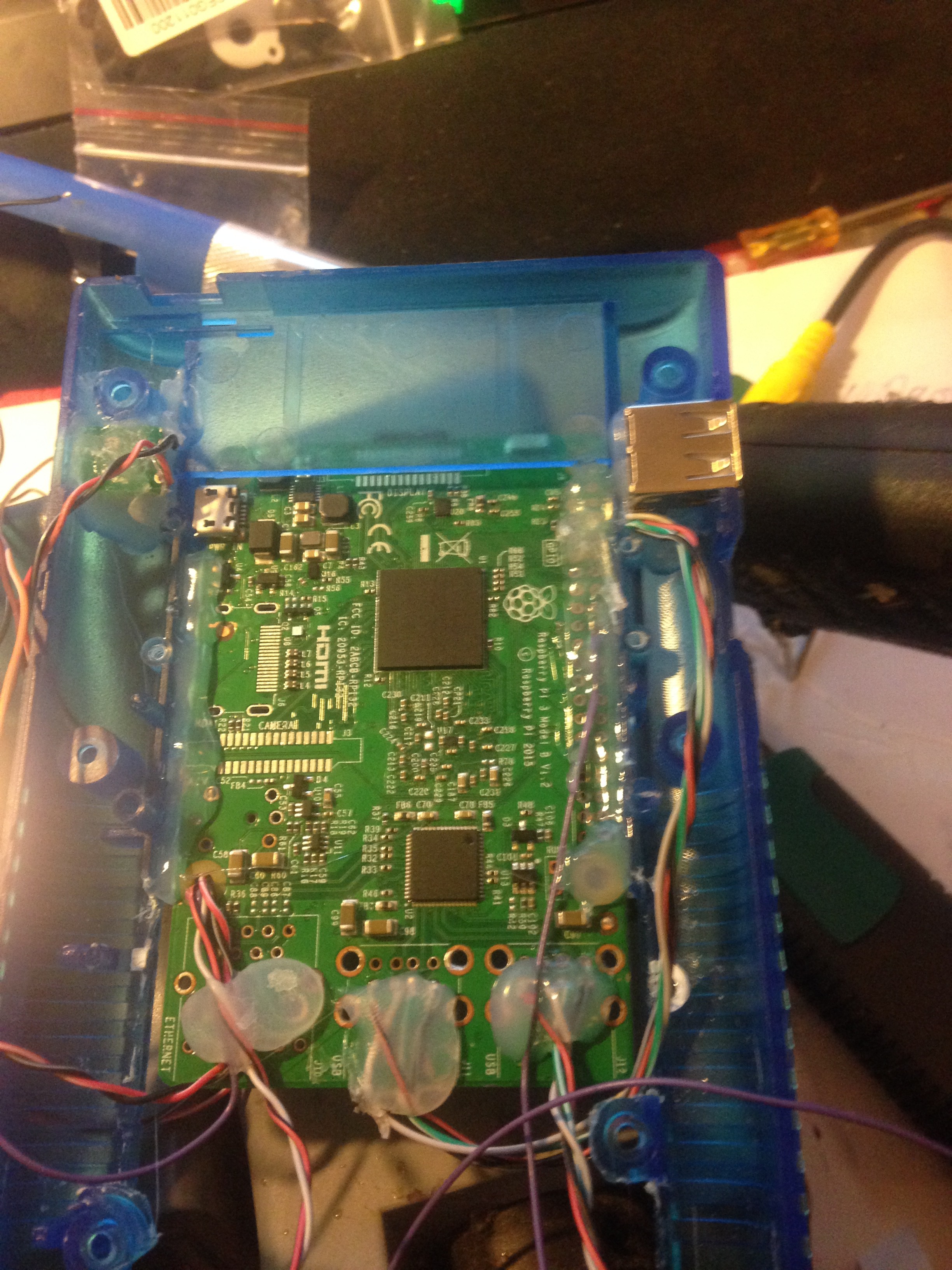
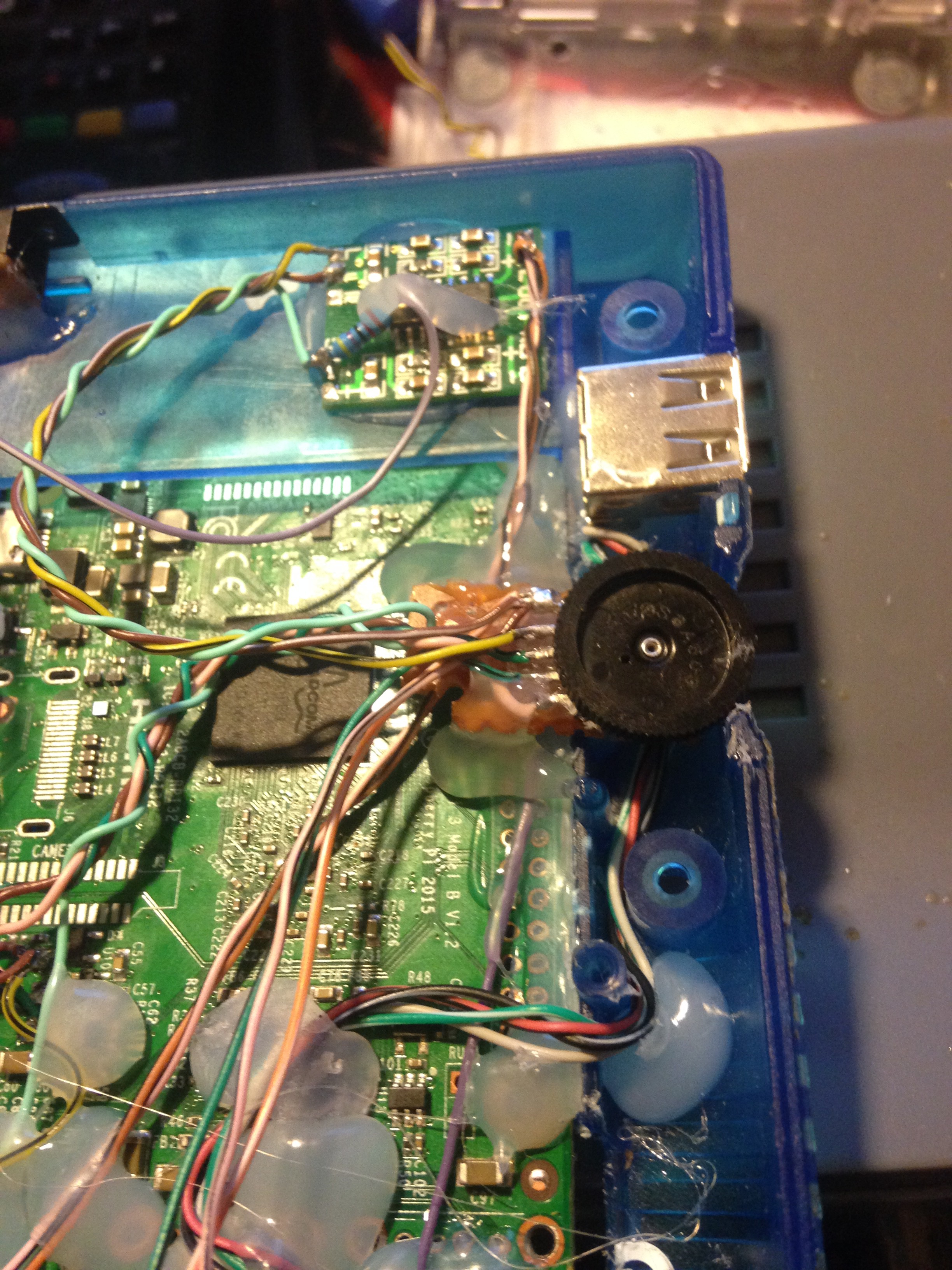
Finaly glued in the Pi in the cartridge slot with the help of your tetris cartrdige to get it aligned right, and also glue in the USB port:
![]()
![]()
Then wire your video & power wires (leave the 2nd USB and audio out for now) to the screen's AV1 input and the power distributor. Don't forget to also solder wires for power to the LCD's controller. Then test everything out
![]()
-
9Step 9
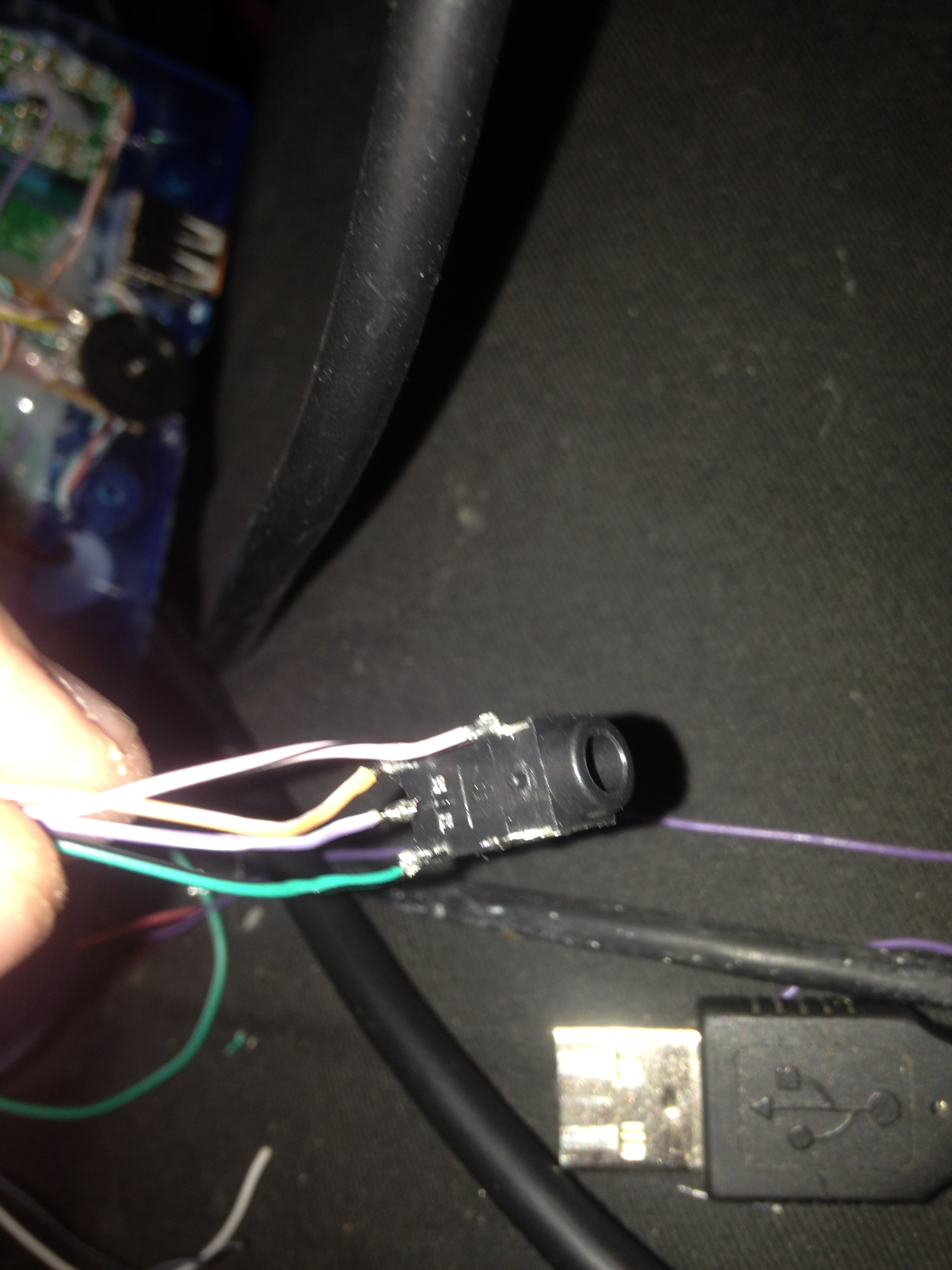
9. Wiring up the amp and heaphone jack
Next up is the audio amplifier, speaker, potentiometer and the headphone jack
The amplifier has to be modified a little bit in order for it to shut down when headphones are plugged in.
For that, pin 12 needs to be desoldered from the board, and a wire soldered to it. It is the shutdown pin. We need to solder on a 10K or 20K pullup resistor to it and VCC, or the amp will stay off all the time:
![]()
![]()
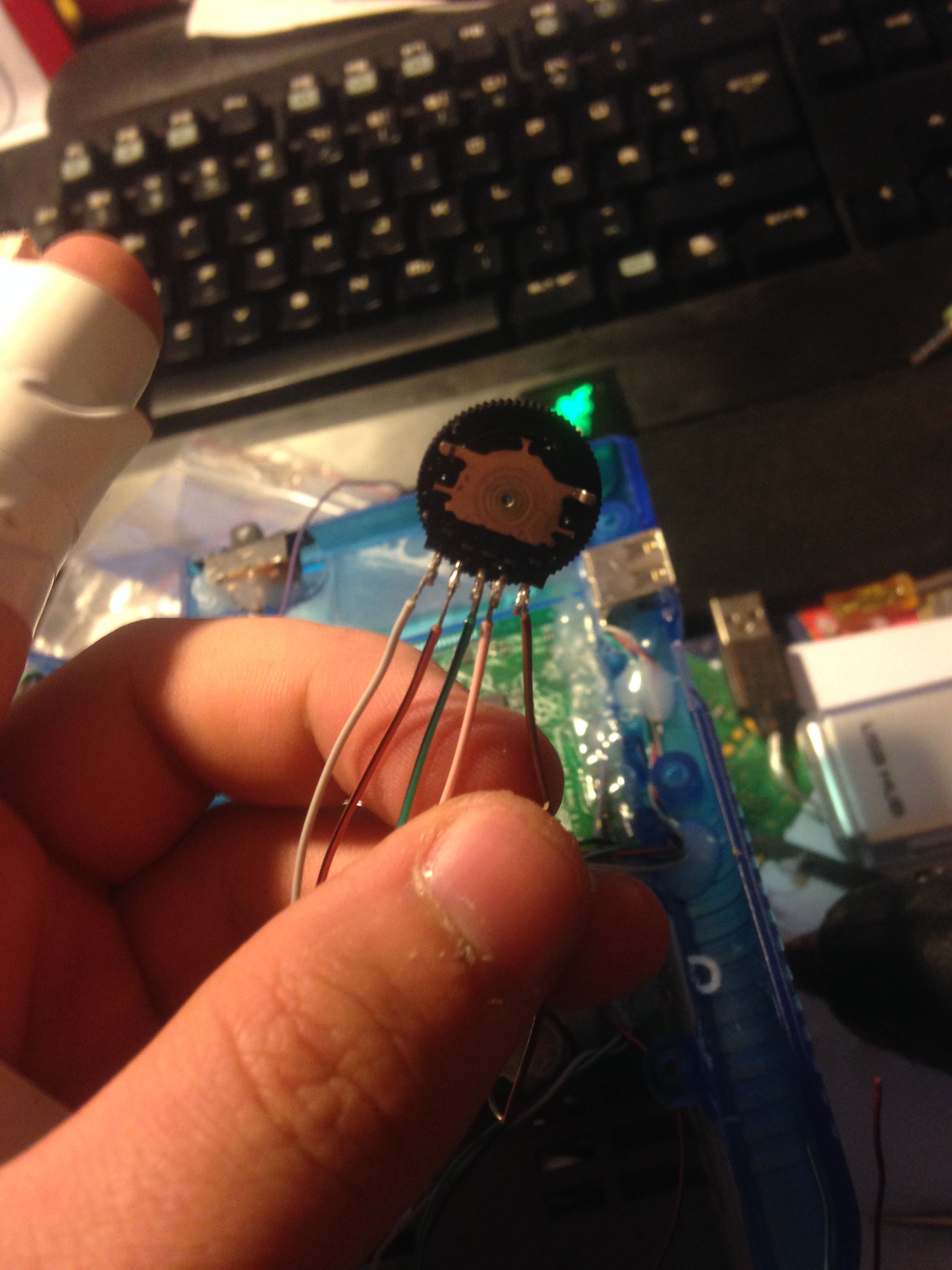
Then the potentiometer is wired to the pi, the amp and the headphone jack. Pins go as following:
1. Left in
2. Right in
3. Right out
4. Left out
5. GND
![]()
(From left to right, bottom ones first):
1. Right
2. Amp's shutdown wire
3. GND
(Upper pins):
1. Left
2. Left
![]()
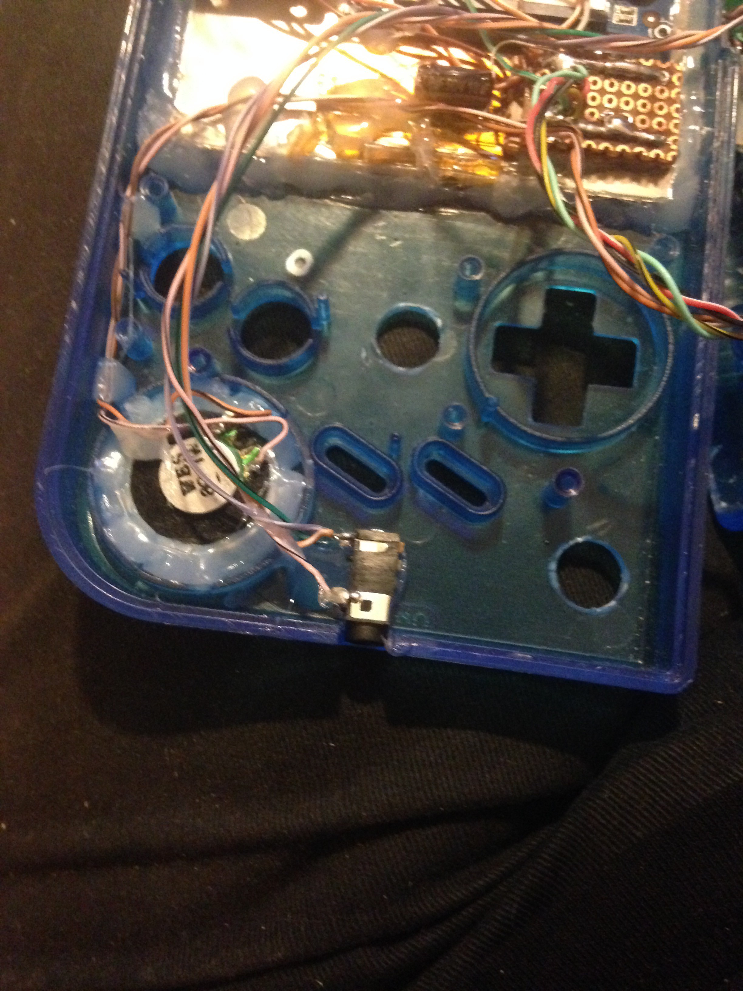
And then wire the speaker to the left output of the amp and glue everything in place (volume wheel with a small piece of perfboard, to raise it up a little):
![]()
![]()
Also, optionaly you can make your sound mono (which I did) by following this instructions (optional):
I included the asound.conf along with this project, but you can also follow along on here to see what the steps are to make it work. I am asuming you already have retropie installed and WiFi set up.
1.) SSH into your Pi with e.g. putty. (you can check the IP adress of it by going to "Show IP adress" inside the retropie menu.
Username: pi
password: raspberry
2.) Now enter the following:
sudo touch /etc/asound.conf
sudo nano /etc/asound.conf
3.) You are now inside the file editor. Copy and paste this:
pcm.card0 {
type hw
card 0
}

ctl.card0 {
type hw
card 0
}

pcm.monocard {
slave.pcm card0
slave.channels 2
# type plug
type route
ttable {
# Copy both input channels to output channel 0 (Left).
0.0 1
1.0 1
# Copy both input channels to output channel 1 (Right).
0.1 1
1.1 1
}
}

ctl.monocard {
type hw
card 0
}

pcm.!default monocard
4.) Press Ctrl + X and confirm that you want to save it with "y". Then press enter, because we don't want to change the filename.5.) Enter the following:
sudo /etc/init.d/alsa-utils restart
That's all.
-
10Step 10
10. Adding a safe shutdown switch
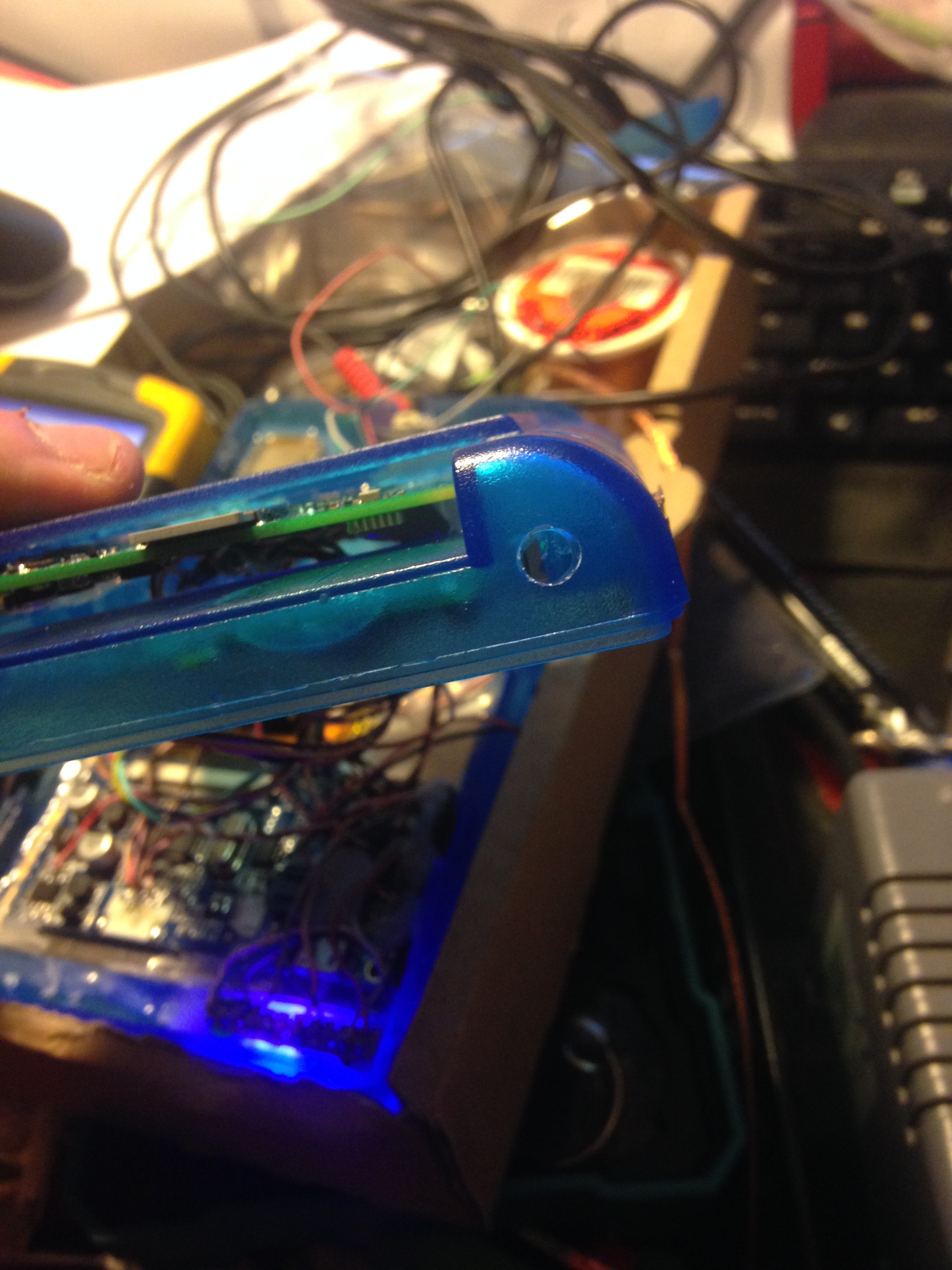
Next up is to add a tactile switch in the upper right to make the pi safely shutdown when this switch is held for 1 second.
Drill a hole for that, solder two wires to the tactile switch so it closes those when the switch is pressed, and glue it in place:
![]()
![]()
Solder a voltage divider consiting of two resistors to the GPIO pin and 5 Volts. This voltage divider simply holds the GPIO pin up to a ~ 3 Volt high state until you press the button. It is important to use it, rather than giving it 5 Volts directly, because that will probably kill your GPIO pin or even the entire pi, because the GPIO logic in the pi is working with 3.3 Volts! So be careful here. The reason we use a voltage divider is that it will come in really handy when you later on hook up your arduino. You can use values like 6.6K and 3.4K. Solder one wire of the switch to GND and the other to the center pin of the voltage divider.
To break it down a little bit easier for you:
Pi GPIO -> 6.6K resistor -> wire of the switch to GND and another wire to the arduino later -> 3.4K resistor -> 5V VCC
To make this switch work, you need to have a deamon running in the background that listens for the keypress event.
I included the shutdown.py along with this project, but you can also follow along on here to see what the steps are to make it work. I am asuming you already have retropie installed and WiFi set up.
1.) SSH into your Pi with e.g. putty. (you can check the IP adress of it by going to "Show IP adress" inside the retropie menu.
Username: pi
password: raspberry
2.) Now enter the following:
touch shutdown.py
nano shutdown.py
3.) You are now inside the file editor. Copy and paste this:
#!/bin/python
# Simple script for shutting down the raspberry Pi at the press of a button.
# by Inderpreet Singh

import RPi.GPIO as GPIO
import time
import os

# Use the Broadcom SOC Pin numbers
# Setup the Pin with Internal pullups enabled and PIN in reading mode.
GPIO.setmode(GPIO.BCM)
GPIO.setup(26, GPIO.IN, pull_up_down = GPIO.PUD_UP)

# Our function on what to do when the button is pressed
def Shutdown():
    os.system("sudo shutdown -h now")

lasttime = time.time()
laststate = 1
# Add our function to execute when the button pressed event happens
while 1:
    if laststate != GPIO.input(26):
        laststate = GPIO.input(26)
        lasttime = time.time()
    if laststate == 0 and lasttime+1< time.time():
        Shutdown()
    time.sleep(0.05)
4.) Press Ctrl + X and confirm that you want to save it with "y". Then press enter, because we don't want to change the filename.5.) Enter the following:
sudo nano /etc/rc.local
6.) add this BEFORE "exit 0", in a new line:
sudo python /home/pi/shutdown.py &
7.) Again, press Ctrl + X and confirm that you want to save it with "y". Then press enter again.
8.) Reboot your pi and confirm that it is working by pressing the button.
Raspberry Pi 3 Gameboy
This is a DIY Raspberry Pi 3 gaming handheld running RetroPie to play all your classics!


Discussions
Become a Hackaday.io Member
Create an account to leave a comment. Already have an account? Log In.
Hey this is awesome, and likely the guide I will follow for building my Pi3Boy . I desire to keep the HDMI port though, how would you approach that?
Are you sure? yes | no