 FabLab München
-
1Software Setup
Currently we are assuming you are using a StereoPi (with CM3). The StereoPi comes with a Raspian image ready to be used with StereoPi and 2 cameras. Make sure you have the latest version, there is an update tgz on that wiki page. To get a 3D image (instead of showing 2 images), you have to do some minor modifications:
in /opt/StereoPi/run.sh replace line
#tvservice -e "CEA 4"
with
tvservice -e "CEA_3D_TB 32 HDMI"
Additionally in /opt/StereoPi/scripts/video_source.sh (line 12) replace
VMOD_STR="-3d sbs"
with
VMOD_STR="-3d tb"
This results in a FullHD output on the HDMI port, with the 2 images placed in "top bottom" configuration, effectively giving you half FullHD resolution. We were not able to archive real FullHD 3D resolution with StereoPi/CM3, but we'll look into if this would be possible with a CM4 board.
You monitor might accept different 3d configurations. To find the correct mode number (32 on the example above) for your monitor use the command
tvservice -m CEA
and look for a mode with a "3d:.." after it. You want a "TB" (top-bottom) or "SBS" (side-by-side) mode. "FP" (frame-packing) is not natively supported by the raspivid tool, which is used to create the video output.
-
2Camera Setup
To archive a good stereoscopic effect, the position and alignment of the cameras are very important. We found the following setup to be a good one:
- distance between cameras and object ca 18-20 cm
- The cameras should be pointed at a common point located on the object to be viewed (parallel positioning does not work as well)
- Make sure the cameras are exactly at the same height and have the same "up" vector (no roll or pitch rotation)
- Place the cameras very close together. A broader base theoretically increase the stereo effect, but tests showed it is not comfortable to look at
Our custom camera stand is designed to archive this setup easily. It lets you adjust the needed parameters (by loosening some screws) but still hold the cameras at exactly the position you want when pleased with the setup (tightening the screws 😆)
-
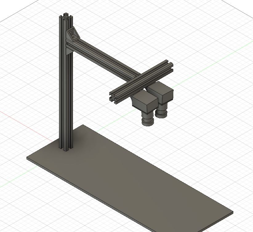
3Building the Stand
We have built a camera stand out of aluminum extrusion and a metal plate as base. This is nice and sturdy and also has some weight, so the cameras do no shake around or come loose.
The components needed for building one:
- 1x Base plate. around 40x15cm, 5mm thick
- 1x 2020 Aluminum extrusion, ~30cm
- 1x 2020 Aluminum extrusion, ~18cm
- 1x 2020 Aluminum extrusion, ~15cm
- 4x 2020 corner brackets 90°. Two of them are used to adjust the camera position and should allow rotation, so use brackets without tabs
- 4x Slot T-nuts
- 8x M5x8
- 4x M5x20
- 4x 2020 corner bracket cover
- 3x 2020 end cover
- 2x camera blocks
The camera blocks are the only custom parts. They allow mounting the cameras to the stand. They obviously have to match the camera model you are using. We simply took small aluminum blocks and glued the camera to one side (we made a small depression in the block, so the camera PCB could lie flat on the block). We added a hole with M5 thread on the back so it can easily mounted to the stand with the corner bracket.
Consider painting/coating the base plate, the metal can short the circuits you want to inspect
![]()
See this project log for detail photos of the stand.
There is also a STEP file available for the stand.
Stereo Ninja
A DIY digital stereo-microscope. Low cost. Open source software and hardware. For electronics inspection, soldering work and more.
Discussions
Become a Hackaday.io Member
Create an account to leave a comment. Already have an account? Log In.