 jean.perardel
-
1How it Works ?
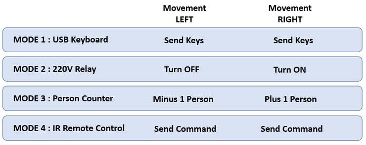
By default GH detects three movements: Left, Right and Up. The left and right movements allow you to send commands depending on the actual mode:
![]()
To switch from one mode to another, simply leave your hand within 15cm of the sensors for 3 seconds. You don't have to use all the mode, just add or remove the mode you are not using on the top of Arduino Program.
![]()
In addition to the different modes, you can always use Pattern Recognition with the upward movement the upward. GH will detect on a 4x4 pixel grid the shape of the object in front of it. The Arduino program allows to easily add Pattern and match it to an action.
-
2[Interface 1] Time Of Flight Sensor and Algorithm
The use of VL53L1 TOF sensor is really interesting. But what makes it different from many competing proximity sensing technologies? (Ultrasonic, Sharp IR angle, LIDAR...)
Beyond the fact that it allows a detection up to 300 inches, a 60Hz refresh rate and a good immunity to light and surfaces reflexion. What I was particularly interested in is called SPAD Array (Single Photon Avalanche Diode) and ROI (Region Of Interrest).
This is because VL53L1 not only detects proximity, it can also target this information to a detection field. The SPADs thus form a 16x16 pixel grid like this :
![]()
There is however some restrictions, the detection area cannot be less than 4x4 pixel. By using a reading of each area without overlapping, one can therefore have a reading of 4 pixels by 4 pixels, i.e. 16 detection zones. The other restriction is speed. Using 16 pixels at 60Hz per reading is barely 4Hz for a full reading. You can find an Arduino/Processing Example on Git repo.
The mode reading Pattern read the 16 ROI and print everything on the LCD.
After several tests, the configuration that seems optimal to detect 3 movements (left, right, up) is with 3 ROI. As soon as a SPAD detects an activity, it trigger a detection_flag to 1. The last SPAD to detect something while this detection_flag is active considers it as a movement in this direction.
In theory we could also do a DOWN motion detection with this pattern. But my algorithms are not yet robust enough and the refresh rate in relation to the motion doesn't make it easier.
To further optimise, I improved the detection by reading all the SPAD at 60Hz. When it trigger something, then I set a detection_flag to 1 and then I start reading my 3 ROI at 17Hz.
There is a lot of testing to be done to optimise ROI for movements detection. If you have any advice, please comment or send me a message.
Of course, by multiplying the sensors, we can multiply the frequency and the number of pixels.
With 4 sensors on the bus :
> We can get the whole field of view at 200Hz
> Focus on 3 opposite areas to detect 4 fast movements "left/right/up/down" at 66Hz
> Read a grid of 8x8 pixels at 3Hz or 1x16 at 12Hz -
3[Interface 2] LCD, emotions and optimisation
![]() One of the challenges on this project is to also run on 8 bits platform like Atmega328p. TOF or relay aren't a real problem but LCD is very complicated for two reasons :
One of the challenges on this project is to also run on 8 bits platform like Atmega328p. TOF or relay aren't a real problem but LCD is very complicated for two reasons :Problem 1 : Memory
With its 32kb of Flash, the Atmega328p can't store a lot of information onboard. Let's imagine that we want to store an image encoded on a RGB565 (2 bytes) of 128x128 pixels. We have : 128x128x2 = 32768 bytes. A single image on a small screen would already completely overload the memory!
Problem 2 : Refresh Rate
To refresh this screen of 16384 pixels it will be necessary to pay also attention to speed. The Atmega328p has only one SPI. If you want to use, for example, an SD card to overcome the memory problem. SD and LCD will be on the same bus. So you will have to do the same on the SPI: get the image from the SD and send it to the LCD...
I found someone who have a solution to this problem HERE, but it implies a RAW storage of the images, which can be quite difficult to stay flexible.
Implementation
To start with, I imagined how to represent my hedgehog with simple shapes that I could generate with the Arduino GFX library. Here, my screen displays the eyes (2 circles) and the nose (1 circle + 3 mini circles) of my hedgehog. I can thus simply use GFX without having to load an image in memory. In addition, I can draw the circles without reloading the whole screen, which allows me to gain a lot of speed.
In order to validate the shapes and movements of the eyes and nose, I started by a simulation on Keynote :
![]()
On the LCD, to implement a movement simply, I used two algorithm :
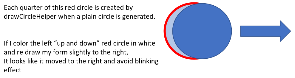
- I redraw the previous shape in black and then I redraw it with color to its new position. This is a very simple way, but it make the screen a bit blinky...
- From GFX Library, to move a "fillCircle()" in a direction, I used a hidden function called "drawCircleHelper()" to remove only a part of the border circle.
![]()
On the Arduino MKR 1010 or Teensy 3.6, I can take advantage of the speed and the extra memory to make my animations more fluid and complex.
On the 3D Design and prototypes, I used a Teensy 3.2.
Speed Max Bit Flash Arduino UNO 16Mhz 8 32kbit Teensy 3.2 96MHz 32 256kbit Teensy 3.6 240Mhz 32 1024kbit MKR 1010 48Mhz 32 256kbit -
4[Interface 3] HID Keyboard
Unlike an Arduino Uno, USB port on MKR 1010 is connected directly to the main micro controller. This feature, also present on Teensy or Arduino Leonardo, offers the possibility to use USB-HID implementation. This allows your project to behave like a keyboard or a mouse.
UNO Board use a second micro controller (Atmega32u2) to transmit data. We can't use USB HID without modification on the 32u2.
Here is Arduino MKR 1010 Schematic :
![From Arduino MKR 1010 Schematic]()
In our case, we will be able to use this specification to send keyboard commands directly to a computer to manage different functions (volumes, movie pause, next episode shortcut...).
Another interesting feature is the presence of PA18 on the 4th PIN of the USB OTG. The activation of this PIN should allow us to reverse the USB master/slave behavior.
After a first test on last version of SAMD library (1.8.6) for MKR 1010. The keyboard wasn't working.It was recognised as a COMport... I found this tutorial explaining that if you downgrade to version 1.6.21 it will work. And it's true :-) But it work great on Teensy board !
-
5[Interface 4] [MKR 1010 only] Wifi Synchronisation with Blynk for Person Counter
To facilitate this part, I used the BLYNK environment to manage the display of data on smartphone. (not possible on Teensy or UNO if you don't add a Wifi board). Blynk allows you to connect a module to a web interface or an application with great ease.
With a limited number of lines of code, one or more objects can be connected to a graphical user interface. It can be used on IOS or Android via a simple TOKEN exchange that will allow to make the link between application and objects.
In WIFI mode, we configure the VL53L1X to extend its range to 4 meters and count the number of people passing in front of it. If it detects movement to the left, it will send a notification to decrement the number of people and the opposite to the right. Thus, with a flow respecting 1 meter of regulatory distance, the BLYNK interface will indicate in real time the number of people inside a room.
![]()
![]()
This application can also be used with several GH to monitor several inputs/outputs. Here is an example :
![]()
-
6[Interface 5] Relay 220V / Servo motor and temperature sensor
For this part, I have created a small outer box allowing me to isolate these components from the main system. Remember that the Servo and Relay work better at 5V, that's the reason I used a Step-Up board to convert my signals voltage (necessary for MKR 1010 and Teensy board).
Sketchup file of the box is available with project files.
-
7[Interface 6] Infrared communication
GH can also learn signals from your IR remote control and send them to your TV.
At the moment, I haven't had time to link this learning function to my system. So it is necessary to use a third party program to do the learning and then copy the frames to be sent to the main program.
The learning program is also available on the GIT Repository.
-
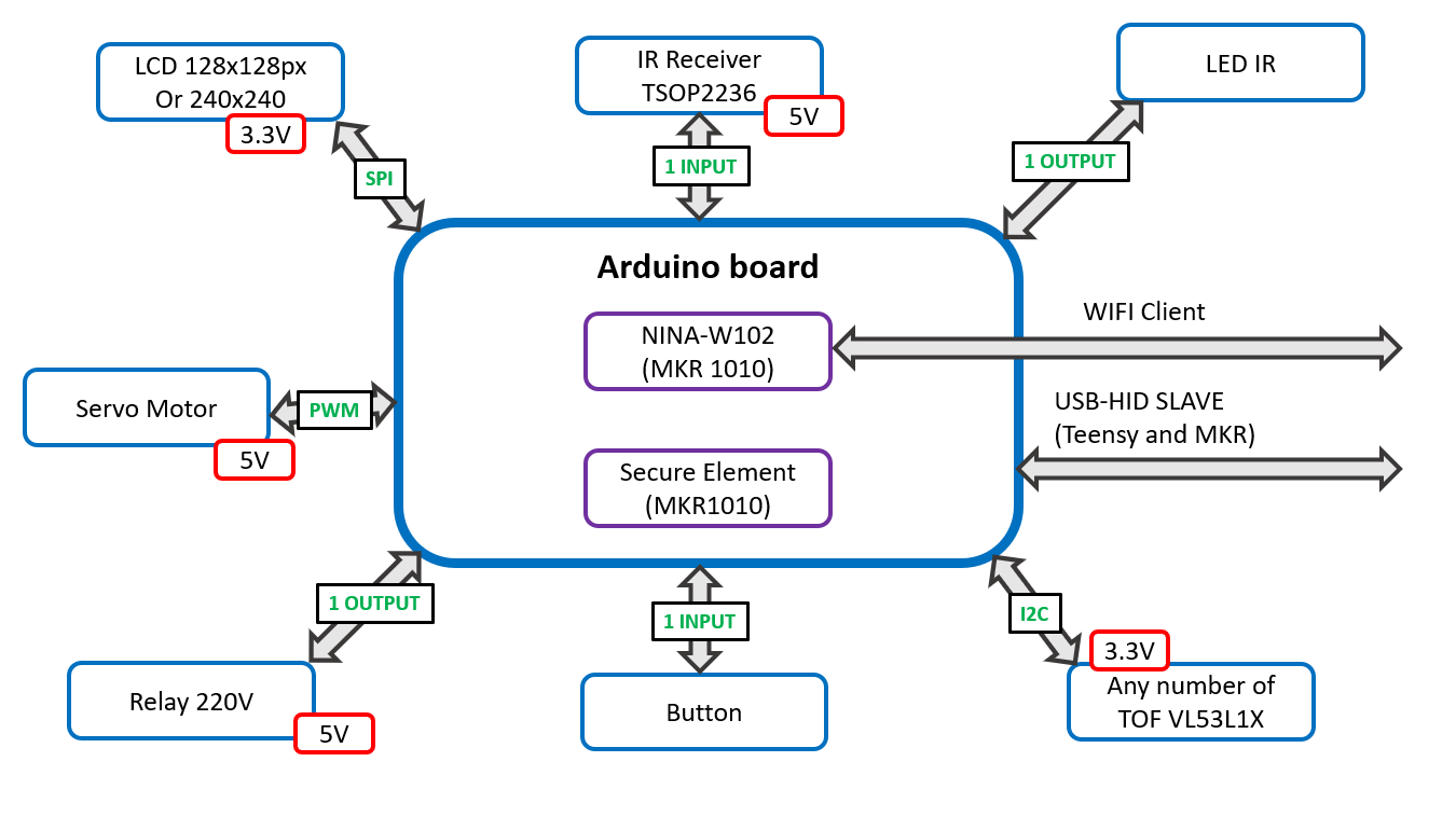
8[Build Instruction 1] Block diagram
![]()
-
9[Build Instruction 2] Hardware
The system includes 2 Breadboard.
The first one (30x15) connects to the TOF sensors and the LCD and distributes the IO with a femelle header 11 PIN.
The second one includes the intelligence (here with a Teensy 3.2), the IR LED, the 11 PIN male header and also a 6 PIN connector to connect relay and servo.
The intelligence board is therefore easily interchangeable by simply remaking the second breadboard.But beware of the size, as a UNO board won't fit in the case. You have to choose an Arduino Mini or Micro board (same contrôler as a UNO).
![]()
-
10[Build Instruction 3] Software
You can find all Software on the Github repository of the project. Here are the librairies I used from the Arduino libraries manager :
- Adafruit_GFX.h & Adafruit_ST7789.h
- SPI.h
- Keyboard.h
- SparkFun_VL53L1X.h
- Wire.h
- WiFiNINA.h (MKR1010)
- BlynkSimpleWiFiNINA.h (MKR1010)
- ArduinoECCX08.h (MKR1010)
Gesture/Pattern Recognition Without Camera : TOF !
Grumpy Hedgehog is a connected device that allows you to read and interact with movements. Its LCD screen displays the Hedgehog's expression


 One of the challenges on this project is to also run on 8 bits platform like Atmega328p. TOF or relay aren't a real problem but LCD is very complicated for two reasons :


Discussions
Become a Hackaday.io Member
Create an account to leave a comment. Already have an account? Log In.