 Radu Pascal
-
1Wiring
Wiring is:
- Black - Ground
- White - to RX on the Arduino
- Green - to TX on the Arduino
- Red - to 5V (3.3v should also do).
![]()
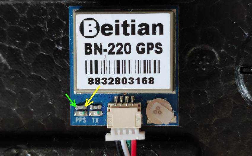
The green and yellow arrows are the test points as shown in the Oscilloscope screenshots.
If you want to embed it into a project, you can either solder a lead to the pad marked by the yellow arrow, or unsolder the Led and the resistor and solder a lead across the resistor pads.
-
2Sketch
The Arduino sketch is pretty simple.
In the Library Manager install "SparkFun u-blox GNSS Arduino Library".
The sketch code (much of it is from the SparkFun Github examples):
#include <SparkFun_u-blox_GNSS_Arduino_Library.h>

// desired frequency
#define FREQ 12000000
// serial for communicating with the host, on Arduino Zero
#define HOST_SERIAL SerialUSB
//serial for pins D0/D1 on Arduino Zero
#define PER_SERIAL Serial1

SFE_UBLOX_GNSS myGNSS;

void setup() {
  // put your setup code here, to run once:
 PER_SERIAL.begin(9600);

  delay(3000);
  if (!myGNSS.begin(PER_SERIAL)){
    HOST_SERIAL.println("\nFailed connecting to GPS module.");
  } else {
    HOST_SERIAL.println("GPS Module connected.");

    HOST_SERIAL.print(F("Version: "));
    byte versionHigh = myGNSS.getProtocolVersionHigh();
    HOST_SERIAL.print(versionHigh);
    HOST_SERIAL.print(".");
    byte versionLow = myGNSS.getProtocolVersionLow();
    HOST_SERIAL.println(versionLow);

    setPPS();
  }
}

void setPPS() {
  // Create storage for the time pulse parameters
  UBX_CFG_TP5_data_t timePulseParameters;

  // Get the time pulse parameters
  if (myGNSS.getTimePulseParameters(&timePulseParameters) == false)
  {
    HOST_SERIAL.println(F("getTimePulseParameters failed! Freezing..."));
    while (1) ; // Do nothing more
  }

  // Print the CFG TP5 version
  HOST_SERIAL.print(F("UBX_CFG_TP5 version: "));
  HOST_SERIAL.println(timePulseParameters.version);

  timePulseParameters.tpIdx = 0; // Select the TIMEPULSE pin
  //timePulseParameters.tpIdx = 1; // Or we could select the TIMEPULSE2 pin instead, if the module has one

  // We can configure the time pulse pin to produce a defined frequency or period
  // Here is how to set the frequency:

  // While the module is _locking_ to GNSS time, make it generate 5Hz
  timePulseParameters.freqPeriod = 5; // Set the frequency/period to 5Hz
  timePulseParameters.pulseLenRatio = 0x55555555; // Set the pulse ratio to 1/3 * 2^32 to produce 33:67 mark:space

  // When the module is _locked_ to GNSS time, make it generate select FREQ
  timePulseParameters.freqPeriodLock = FREQ; // Set the frequency/period
  timePulseParameters.pulseLenRatioLock = 0x80000000; // Set the pulse ratio to 1/2 * 2^32 to produce 50:50 mark:space

  timePulseParameters.flags.bits.active = 1; // Make sure the active flag is set to enable the time pulse. (Set to 0 to disable.)
  timePulseParameters.flags.bits.lockedOtherSet = 1; // Tell the module to use freqPeriod while locking and freqPeriodLock when locked to GNSS time
  timePulseParameters.flags.bits.isFreq = 1; // Tell the module that we want to set the frequency (not the period)
  timePulseParameters.flags.bits.isLength = 0; // Tell the module that pulseLenRatio is a ratio / duty cycle (* 2^-32) - not a length (in us)
  timePulseParameters.flags.bits.polarity = 1; // Tell the module that we want the rising edge at the top of second. (Set to 0 for falling edge.)

  // Now set the time pulse parameters
  if (myGNSS.setTimePulseParameters(&timePulseParameters) == false)
  {
    HOST_SERIAL.println(F("setTimePulseParameters failed!"));
  }
  else
  {
    HOST_SERIAL.println(F("Success!"));
  }
}

void loop() {

  delay(1000);

}
A few things that you can just change out of the box:
FREQ - set to the desired frequency.
HOST_SERIAL - the serial to use for communicating to the host (meaning your computer).
PER_SERIAL - the serial for communicating to the GPS module.
The last two you might need to change depending on the flavour of your Arduino. The #defines are set for Arduino Zero (Adafruit Metro M0 if to be precise).
And the expected output is:
GPS Module connected.
Version: 18.0
UBX_CFG_TP5 version: 1
Success!
Your Red LED should be flickering at a 5Hz frequency until a GPS lock is acquired. After that it should change to constant red if your FREQ frequency is high enough (probably over 50Hz).
-
3Enjoy
Enjoy a Reference Frequency that you can use either to calibrate a frequency counter, or use it as a oscillator for your project.
Cheap GPS Disciplined Oscillator
A 13$ GPS Disciplined Oscillator using Beitian BN220
Discussions
Become a Hackaday.io Member
Create an account to leave a comment. Already have an account? Log In.